CREATING DEVS COMPONENTS WITH THE METAMODELLING TOOL ATOM3 Andriy Levytskyy† Eugène J.H. Kerckhoffs
Faculty of Information Technology and Systems Mediamatica Department Delft University of Technology, Mekelweg 4, 2628 CD Delft, The Netherlands
[email protected]
KEYWORDS DEVS, Metamodelling, Graph Transformation, Domain-specific Modelling and Simulation Environments. ABSTRACT DEVS is a well-known formalism that provides a rigorous basis for discrete event modelling and simulation. In this paper we present two possible DEVS metamodels that are used to automatically generate 1) a tool that allows the graphical definition of DEVS models and 2) Zope products that allow storing DEVS models in a model library under the Web Application Server Zope. The tool is capable of generating a representation suitable for simulation by an external DEVS solver. The generation of executable model representations and Zope products is realized by graph transformation. The tool, the simulator and the model library form a dedicated DEVS modelling and simulation environment. The paper demonstrates how dedicated, domain/problem-specific modelling and simulation environments can be easily generated from metamodels using graph transformation. 1.
INTRODUCTION The emergence of the world-wide web (WWW) and its popularity in the simulation community gave birth to the concept of web-based simulation (Fishwick 1996). This now includes (among others) activities that deal with the use of the WWW as an infrastructure to support distributed simulation execution. It also encompasses research into tools, environments and frameworks that support the distributed, collaborative design and development of simulation models (Page 1998). Within this context we started a Collaborative Simulation project in which a generic web environment is developed to support simulation and modelling components in multidisciplinary collaborative projects (Levytskyy and Kerckhoffs 2000a). The practical application of our prototyped environment lies in the †
Ernesto Posse Hans Vangheluwe
Modelling, Simulation and Design Lab (MSDL) School of Computer Science McGill University 3480 University St., Montréal, Quebec, Canada H3A 2A7 http://msdl.cs.mcgill.ca
NanoComp project (nanocom.et.tudelft.nl), which investigates computing systems based on quantum devices. Hence is the name NanoComp Simulation Environment (NCSE). The environment’s functionality is similar to that of the DLR-Virtual Laboratory (Ernst et al. 2003) and provides registered (web-)users with model registration and access to experiments. Registered models and tools are treated as limited Internet resources and are organized into a central Model Library. NCSE itself runs on top of the Web Application Server Zope (www.zope.org) and its resources are created from Zope products. Since 2002, all major parts of the environment are no longer coded, but rather (meta)modelled. Code is automatically generated by means of AToM3 (A Tool for Multi-formalism and Meta-Modelling) (de Lara and Vangheluwe 2002), which is also a part of the NCSE as a generic modelling client. AToM3 is a visual tool that uses metamodelling and graph grammars to specify and generate domain-specific environments. Metamodelling refers to modelling formalism concepts at a meta-level, and model transformation refers to the automatic conversion, translation or modification of a model of a given formalism into another model in the same or different formalism (Vangheluwe et al. 2002).
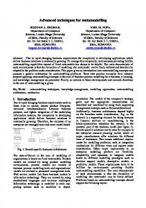
Figure 1: NCSE within a Metamodelling and Graph Transformation Framework
Part of this work was carried out while the first author was a visiting researcher at the MSDL.
Proceedings 15th European Simulation Symposium Alexander Verbraeck, Vlatka Hlupic (Eds.) (c) SCS European Council / SCS Europe BVBA, 2003 ISBN 3-936150-28-1 (book) / 3-936150-29-X (CD)
This paper demonstrates how meta-modelling and graph transformation can be used to construct a modelling and simulation environment, in this particular case dedicated to DEVS, a well-known formalism that provides a rigorous basis for discrete event modelling and simulation (Zeigler et al. 2000). Figure 1 depicts the process of constructing a DEVS environment within the NCSE. There are three domains: “AToM3” , “File System” and “Zope”. “Meta” and “Model” levels span across these domains. Their intersections create six zones. A number of models specified in various formalisms are present in the figure. Graph Grammar models specify transformations. When applied to a model, they convert it into another form and, only specific to our depiction, may transfer it into a different zone. We use _ syntax to name models throughout the paper. For example, DEVS_ER denotes a (meta)model of the DEVS formalism, described in the Entity Relationship (ER) formalism. Similarly, ER2SCD_GG denotes a model of the transformation between a model in the ER formalism into its equivalent in the Simplified Class Diagrams (SCD) formalism, described in the Graph Grammar (GG) formalism. AToM3 allows one to create a DEVS metamodel in a formalism, such as ER (zone 1 in Figure 1). The ER2SCD_GG transformation automatically converts DEVS_ER into another form: DEVS_SCD, which is the starting point for automated code generation for Zope. SCD2ZProduct_GG produces DEVS Products for Zope (zone 3), from which clients can create containers for DEVS models at the lower level (zone 6). The DEVS tool itself (zone 4) is automatically generated from metamodel DEVS_ER via ER2MM_GG, an internal AToM3 graph transformation discussed in (de Lara and Vangheluwe 2002). This tool provides DEVS2PythonDEVS_GG, a transformation, which converts any valid DEVS models into a representation (zone 5) executable by an external solver. Communication between the DEVS tool (zone 4) and NCSE resources (zone 6) is being implemented. The rest of the paper is organized as follows. Section 2 presents two possible DEVS metamodels. Section 3 presents the DEVS tool (generated from the first metamodel). Section 4 discusses the code generation schemes for an external DEVS solver and for Zope. Section 5 concludes the paper with final remarks. 2.
METAMODELLING DEVS Metamodelling refers to the definition or description of modelling languages or formalisms. A metamodel of a given formalism specifies the syntax of the formalism by defining the language constructs and how they are built-up in terms of other constructs. To construct a DEVS metamodel we use Entity Relationship (ER) diagrams extended with constraints.
This is the default meta-formalism of AtoM3. Constraints further restrict how a construct can be connected to another construct to be meaningful. Each DEVS modelling construct is specified with attributes, constrained with constraints, visually presented with its appearance and participates in relationships according to its cardinality. We define each construct’s attributes with a minimum collection of features that form the basis for the DEVS semantics.
Figure 2: DEVS Metamodel in ER The screenshot in Figure 2 illustrates how ER constructs build up a DEVS metamodel (Posse and Bolduc 2003). Note that constraints and appearance are element properties, which are not visible in the used notation. A brief formal specification of ER elements is given below (constraints and cardinalities are omitted to save space): atomic_devs implements a basic DEVS model with ports. It is a container for states and for the DEVS functions time advance, internal transition, external transition and output. attributes name is a unique identifier of a component: String parent is a quasi-feature that returns the reference to the parent of the atomic_devs in a hierarchical model via the contains_model relationship: coupled_devs ports is a quasi-feature that returns a collection of references to input and output ports via the contains_port relationship: Set {port} states is a quasi-feature that returns a collection of references to DEVS states via the contains_state relationship: Set {state}
Figure 3: Atomic DEVS Appearance
appearance An atomic DEVS is represented as solid rectangle with its name above the top left corner (see Figure 3). It may contain states connected by transitions.
state allows a modeller to add a DEVS state to an atomic model and specify behaviour. attributes name is a unique identifier of a component: String initial is a marker for the initial state: Boolean internal_transition is a quasi-feature that specifies the internal transition via the internal_transition relationship: Constraint text external_transition is a quasi-feature that specifies the external transition via the external_transition relationship: Constraint text output is the output function: Constraint text time_advance is the time advance function: Constraint text
Figure 4: State Appearance appearance A state is represented as solid gray circle with its name in the center (see Figure 4).
coupled_devs is a model expressed in Coupled DEVS with ports. It is a container for atomic and coupled models. In case of Classic DEVS, the modeler has to implement the tie-breaking function select. attributes name is a unique identifier of a component: String parent is a quasi-feature that returns the parent of the coupled_devs in a hierarchical model via the contains_model relationship: coupled_devs ports is a quasi-feature that returns a collection of references to input and output ports via the contains_port relationship: Set {port} children is a quasi-feature that returns a collection of references to children components via the contains_model relationship: Set {DEVS} EIC is a quasi-feature that returns a collection of external input couplings via the channel relationship: Set {((coupled_devs, inport), (DEVS, inport))} EOC is a quasi-feature returning a collection of external output couplings via the channel relationship: Set {((DEVS, outport), (coupled_devs, outport))} IC is a quasi-feature that returns the collection of internal couplings via the channel relationship: Set {((DEVS, outport), (DEVS, inport))} select is the tie-breaking function: Constraint text appearance A Coupled DEVS presentation is the same as that of the Atomic DEVS, but instead of states, it may contain instances of atomic_devs and coupled_devs.
port is a component's input or output interface. attributes name is a unique identifier of a component: String port_type specifies if the port is for input or output: Enum { input, output }
Figure 5: Port Appearence appearance A port is represented as small (relative to the other appearances) square with its name labeled next to it (see ).
channel is responsible for specifying input/output connections between interfaces (ports) of DEVS components. Note on cardinality: one outport can be connected to many inports. appearance A channel is represented as solid connector with an arrow end pointing to the input interface (port) of a component.
Along with the properties defined for each DEVS construct, a modeller can add global properties for the metamodel itself to, for example, document models belonging to this family of the DEVS formalism. All global properties and regular attributes are to be filledin at the lower meta-level.
Figure 6: DEVS Metamodel in SCD Figure 6 shows another DEVS metamodel (DEVS_SCD) expressed in the Simplified Class Diagrams (SCD) formalism (Levytskyy and Kerckhoffs 2003), a custom UML Class Diagrams-like formalism designed with AToM3 for the NanoComp project. This metamodel is equivalent to the previously described DEVS_ER, but is less detailed: it is stripped of any syntax related to graphical nature, and any constraints related to well-formedness rules that are required for
modelling tools. The model shown is the result of automated transformation from the DEVS metamodel in ER into the SCD formalism by means of graph rewriting. This rather straightforward graph transformation is beyond the scope of this paper. DEVS_SCD model is created solely for the purpose of code generation for Zope. We will return to it in subsection 4.2. 3.
THE TOOL Given the DEVS_ER metamodel, AToM3 can generate (by means of ER2MM_GG as illustrated in Figure 1) a meta-specification, which, when loaded into the meta-level of AToM3, turns it into the modelled DEVS tool. A part of this meta-specification is a specification of the User Interface. This specification is a model in its own right and can be edited in AToM3 at any time in the “Buttons” formalism. By default, this specification creates a button for every construct of the formalism. An instance of the generated DEVS modelling tool with a simple DEVS model on its canvas is shown in Figure 6. For a complete description of this tool, we refer to (Posse and Bolduc 2003).
External transitions between states also have an additional attribute which may contain some Python script to specify whether the transition is enabled or not. This script has as parameters the source state, the elapsed time, and the values at the input ports. It should return true or false. For example, if there is an external transition link between two states s0 and s1, labelled with a condition such as e < 1.0 and x1 = 3, where e is a variable representing the elapsed-time since the last transition, and x1 is the name of some input port, then the external transition will take place if the condition becomes true. All these attributes for ports, states and external transitions can be specified by using the Edit button. The Generate simulator button is used to produce the Python code for the DEVS model on the canvas. The generated code is a textual representation of DEVS models that can be used by the PythonDEVS simulator (Bolduc and Vangheluwe 2002), an implementation of the standard classic DEVS simulation algorithm. The underlying graph transformation (Posse and Bolduc 2003) is briefly described in subsection 4.1. 4.
Figure 7: Generated DEVS Modeling Tool In this tool, the user can create coupled or atomic DEVS models by clicking the corresponding button on the left and then clicking in the canvas. The same applies for each element that forms a DEVS model (states, ports, channels, and transitions.) To create a channel between ports, or a state transition, the user clicks on the Connect button, then clicks on the source and finally on the target. If the link is a state transition, the user is asked to select whether it is an internal or an external transition. To specify that a component is part of another (e.g. a submodel, or a port,) the user clicks on the Connect button, then clicks on the “parent”, and finally on the “child”. Each graphical element, which is not a link, has a label with its name. This can be edited using the Edit button. Ports are labelled as either input or output ports. Each state has two attributes apart from its name. These are two fields which may contain an arbitrary Python script to specify the time-advance and output for the state.
GRAPH TRANSFORMATION One approach to manipulate graphical structures, such as our representation of DEVS models, is graph transformation. Graph transformation extends the idea of term rewriting to arbitrary graphs. The theory behind graph transformation has been thoroughly studied (see for example (Rozenberg 1999)), but there are still few software tools that support it. AToM3 is one such tool. The central notion in graph transformation is that of a graph grammar. A graph grammar is a collection of productions or rules specifying how a (sub)graph of a so-called host graph can be replaced by another (sub)graph. Some graph grammars are enriched by associating with each rule, some additional conditions and actions. These can be used to model side-effects. Informally, the operational semantics of graph grammars is as follows. We start from a host graph and a graph grammar. A direct derivation is the result of matching some subgraph of the host graph to the lefthand side of some rule in the grammar, checking if the additional condition is true, and if so, replacing that subgraph by the corresponding right-hand side of the rule, subsequently performing any additional actions associated with the rule. Some graph rewriting systems associate priorities to the rules, so that if more than one rule matches the host graph, the priorities act as tiebreakers. An execution or trace is a sequence of direct derivations1. 1
This informal definition, as implemented in AToM3, is most closely related to the so-called SPO approach to graph transformation (Rozenberg 1999; Ehrig 1979).
Graph transformation has been used in a plethora of applications, such as specifying the operational semantics of graphical languages, and specifying formalism translations. This paper demonstrate two graph transformations that generate Python code (see below). Code generation can be understood in terms of formalism transformation where the original representation is the source formalism and the language of the generated code is the target formalism. While it is theoretically possible to provide a purely graphical translation from a formalism such as DEVS into a real programming language such as Python, it is not a very practical approach, since it would require defining a meta-model for the target language. Real programming languages have too many constructs and special cases to make this approach feasible in practice. However, we can still have a graph transformation approach since rules in a graph grammar can have associated actions encoding side-effects. In our approach we use the graphical nature of the source formalism to traverse and annotate the model which is being translated, while the rule's actions generate the associated code. 4.1 PythonDEVS Code Generation In order to generate simulators from DEVS models represented graphically we use graph transformation. This, however, requires us to introduce some extensions to the meta-model. In particular we need some “pointers” or “markers” to traverse the DEVS model and mark which submodels have been already processed. There are two equivalent approaches to this: 1) use a graphical pointer, or 2) use an attribute in the nodes to represent the fact that a node has already been visited. Our graph grammar uses the second approach. Another issue in the code generation scheme is that for a given model node we might require access to several of its neighbour nodes to generate its code. For instance, when generating code for any model we need to know which are the node's ports, or when generating code for a coupled model we need to know which are its submodels. None of these situations can be handled by a single rewriting rule, since the left-hand side of a rule always has a fixed number of nodes, but we need to apply the rule of interest for an arbitrary number of neighbours. One possible solution is to create a special “collecting” node, and have a rule that adds the neighbours to a list in this collecting node. This rule, when applied, marks each neighbour as visited so that it is not added twice. The rule also should have a priority higher than that of the actual code generation of the model of interest, since code generation should happen only after all the relevant neighbour's information has been collected. The code generation rules themselves do not perform any important rewriting aside from getting rid of annotations such as the collecting nodes mentioned
above. The code generation is performed by the actions, which can access the annotations. An example of the code generation rule of a coupled model, showing the collecting nodes is depicted in Figure 8. The collecting nodes (S and P) each contain a list of the names of the submodel nodes and port nodes respectively. The rule simply deletes the annotations (the collecting nodes,) and its action is to call an external function passing it the model and the relevant annotations. The action is executed before the graph rewriting takes place. The rule also marks the model's node as visited so that it will not be applied again to that node.
Figure 8: A Typical Code Generation Rule As an example, consider the model in Figure 7. In the atomic model A, there is an external transition labelled evt from state s0 to state s1. This transition has as condition the following script: if e < 1.0: if i1 == 'a' and i2 == 0 or i1 == 'b' or i2 > 0: return 1 else: return 0 elif e < 2.0: return i2 >= 1 else: return 0
where 0 stands for false and 1 for true, following Python's convention. Then the PythonDEVS code generated for A, is as follows: class A(AtomicDEVS): def __init__(self): AtomicDEVS.__init__(self) self.state = 's0' self.elapsed = 0.0 self.i1 = self.addInPort() self.i2 = self.addInPort() self.o1 = self.addOutPort() self.o2 = self.addOutPort() def extTransition(self): s = self.state e = self.elapsed i1 = self.peek(self.i1) i2 = self.peek(self.i2) if s == 's0': def guard1_condition(e, i1, i2): if e < 1.0: if i1 == 'a' and i2 == 0 or i1 == 'b' or i2 > 0: return 1 else: return 0 elif e < 2.0: return i2 >= 1 else: return 0 if guard1_condition(e, i1, i2): return 's1'
4.2 Zope Product Generation The sequel describes the transformation SCD2ZProduct _GG, which, given an SCD model (in this case, DEVS_SCD), can generate Python code for a corresponding Zope product. This transformation also extends the source model with “markers” in a way
similar to that described above. A detailed description of this transformation can be found in (Levytskyy and Kerckhoffs 2003). Figure 9 shows a somewhat modified part of the metamodel related to the “Atomic DEVS” component. The core of this diagram is concrete class atomic_devs. In addition, we created two “dummy” classes MRD (Metadata for Resource Discovery) and ARV (Abstract Resource View) that are defined outside the namespace of this model. These “imported” classes provide features that enable on-line registration, discovery and processing of NCSE resources (Levytskyy and Kerckhoffs 2001).
Figure 9: Atomic DEVS Component The result of the SCD2ZProduct_GG transformation applied to the diagram in Figure 9, is a valid Python package implementing a Zope product. An excerpt of the code generated for Atomic DEVS product is class atomic_devs(mxmSimpleItem, MRD, ARV): meta_type = 'atomic_devs' _allowed_meta_types = ('state', 'port') _properties = ( {'type': 'string', 'id': 'name'}, ) + MRD._properties + ARV._properties def parent (self): '''Return the parent coupled_devs.''' return self.getParentNode() def states (self): '''Return states of this atomic_devs.''' return self.objectValues('state') def ports (self): '''Return ports of this atomic_devs.''' return self.objectValues('port') index_html = HTMLFile('www/index_html', globals())
At this point, a Zope developer can finalize the synthesized product by for example specifying an implementation of the public interface index_html in the external HTML file www/index_html, and install the package in the Products directory of the Zope installation. After Zope has been restarted, a new type of objects, namely atomic_devs, can be created under Zope in the NCSE Model Library. These new objects, just like any other NCSE resources, are easily documented, searchable and executable on-line in a standard manner (Levytskyy and Kerckhoffs 2001). 5.
CONCLUSIONS In this paper we have introduced a DEVS modelling environment, which allows the graphical definition of DEVS models, generates well-structured dedicated simulators for the models and allows storing the models in a central repository in a consistent manner. We also emphasize metamodelling and graph transformation as suitable frameworks for the construction of such dedicated modelling and simulation environments. Future work will be done to implement the communication between the DEVS tool (zone 4) and the NCSE Model Library (zone 6) as shown in Figure 1. This connectivity will enable us to store semantic information of DEVS models (both atomic and coupled) in the Model Library under Zope and later, retrieve this information into the DEVS tool to reuse it in modelling components. This implements the contextout and context-in ideas introduced by (Bernardi and Santucci 2003) ACKNOWLEDGEMENT The research reported in this paper is done in the framework of the NanoComp project, sponsored by the TU-Delft, and in close co-operation with the Modelling, Simulation and Design Lab (MSDL) of the School of Computer Science of McGill University, Montréal, Canada. The authors wish to thank Juan de Lara of Universidad Autónoma de Madrid, Spain, for his work on AToM3. REFERENCES
Bernardi, F. and J.-F. Santucci. 2003. “Domain Management in a Hierarchical Generic Models Library”. In A. Bruzzone and Mhamed Itmi, editors, Summer Computer Simulation Conference, pp. 855 – 860. Society for Computer Simulation International (SCS), July 2003. Montréal, Canada. Bolduc, J.S. and H. Vangheluwe. 2002. “A modeling and simulation package for classic hierarchical DEVS”. Technical report, Modelling, Simulation and Design Lab (MSDL), School of Computer Science, McGill University. http://moncs.cs.mcgill.ca/ MSDL/research/projects/DEVS/ de Lara, J. and H. Vangheluwe. 2002. “AToM3: A Tool for Multi-Formalism Modelling and Meta-Modelling”. In: European Conferences on Theory And Practice of
Software Engineering ETAPS02, Fundamental Approaches to Software Engineering (FASE). Lecture Notes in Comp. Sc. 2306, Springer-Verlag, pp.174 – 188. Ehrig, H. 1979. Introduction to the algebraic theory of graph grammars (a survey). 73:1-69, 1979. Ernst, T.; T. Rother; F. Schreier; J. Wauer; and W. Balzer. 2003. “DLR’s VirtualLab: Scientific Software Just a Mouse Click Away”, Computing in Science & Engineering magazine, vol.5, no.1, Jan./Feb.: pp. 70-79 Fishwick, P.A. 1996. “Web-Based Simulation”. In: Proceedings of the 1996 Winter Simulation Conference, pp. 772 – 779. Levytskyy, A. and E.J.H. Kerckhoffs. 2000. “Towards a Prototype Web-Based Collaborative Simulation Environment”, SCS: paper of the 5th Euromedia Conference, May 2000, pp. 60 – 66. Levytskyy, A. and E.J.H. Kerckhoffs. 2001.“Integration of Simulation Tools and Models in a Collaborative Environment”. In: Proceedings of 2001 European Simulation Interoperability Workshop (London, United Kingdom, June 25-27), Simulation Interoperability Standards Organisation, pp. 407 – 415. Levytskyy, A. and E.J.H. Kerckhoffs. 2003. “From Class Diagrams to Zope Products with the Meta-Modelling Tool AToM3”. In A. Bruzzone and Mhamed Itmi, editors, Summer Computer Simulation Conference, pp. 295 – 300. Society for Computer Simulation International (SCS), July 2003. Montréal, Canada. Page, E. H. 1998. “The rise of Web-based simulation: implications for the high level architecture”. In: Proceedings of 1998 conference on Winter simulation (Washington, D.C., United States), pp. 1663 – 1668. Posse, E. and J.-S. Bolduc. 2003. “Generation of DEVS Modelling & Simulation Environments”. In A. Bruzzone and Mhamed Itmi, editors, Summer Computer Simulation Conference. Student Workshop, pp. S139 - S146. Society for Computer Simulation International (SCS), July 2003. Montréal, Canada. Rozenberg, G., editor. 1999. Handbook of Graph Grammars and Computing by Graph Transformation: Foundations, volume 1. World Scientific. Vangheluwe, H.; J. de Lara; and P.J. Mosterman. 2002. “An introduction to multi-paradigm modelling and simulation”. In: Fernando Barros and Norbert Giambiasi, editors, Proceedings of the AIS'2002 Conference (AI, Simulation and Planning in High Autonomy Systems), Lisboa, Portugal, April, pp. 9 – 20. Zeigler, B. P.; H. Praehofer, and T. G. Kim. 2000. Theory of Modeling and Simulation. Second Edition. Academic Press, San Diego, USA.
AUTHOR BIOGRAPHIES Andriy Levytskyy graduated from Chernivtsi State University, Ukraine and holds an MSc-degree in Computer Science. Currently, he is a final year PhD student at Delft University of Technology, Faculty of Information Technology and Systems, Mediamatica Department. His main interest is in constructing domain-specific modelling and simulation environments. Eugene J.H. Kerckhoffs holds an MSc-degree from Delft University of Technology (1970, Physical Engineering, thesis on analogue and hybrid computer simulation) and a PhD-degree from Ghent University (1986, Computer Science, thesis on parallel continuous simulation). Currently, he is an associate professor at Delft University of Technology (Faculty of Information Technology and Systems, Mediamatica Department, Knowledge-based Systems Group). He was also a holder of the SCS Chair in Simulation Sciences at the University of Ghent, Belgium. His main interests are in neural and numeric computing, and in knowledge engineering. Ernesto Posse is a PhD student at the School of Computer Science of McGill University (Montréal, Quebec, Canada) working in the Modelling, Simulation and Design Lab. His main interest is in metamodelling of dynamic-structure systems. Hans Vangheluwe is an Assistant Professor in the School of Computer Science at McGill University, Montréal, Canada. He holds a DSc degree, as well as an M.Sc. in Computer Science, and BSc degrees in Theoretical Physics and Education, all from Ghent University in Belgium. At McGill University, he teaches Modelling and Simulation, as well as Software Design. He also heads the Modelling and Simulation and Design (MSDL) research lab. He has been the Principal Investigator of a number of research projects focused on the development of a multi-formalism theory for Modelling and Simulation. He is an Associate Editor for the journal Simulation: Transactions of the Society for Modelling and Computer Simulation. His main interest is in (meta)modelling domain-specific modelling and simulation environments.