a system for generating reactor core geometry and mesh models that ..... In the
three-stage process described above, 3D assembly models and meshes are ...
Creating Geometry and Mesh Models for Nuclear Reactor Core Geometries Using a Lattice HierarchyBased Approach Timothy. J. Tautges Argonne National Laboratory (608) 263-8485 (608) 263-4499
[email protected] http://www.mcs.anl.gov/~tautges
Rajeev Jain Argonne National Laboratory (630) 252-3176
[email protected]
Abstract Nuclear reactor cores are constructed as rectangular or hexagonal lattices of assemblies, where each assembly is itself a lattice of fuel, control, and instrumentation pins, surrounded by water or other material that moderates neutron energy and carries away fission heat. We describe a system for generating geometry and mesh for these systems. The method takes advantage of information about repeated structures in both assembly and core lattices to simplify the overall process. The system allows targeted user intervention midway through the process, enabling modification and manipulation of models for meshing or other purposes. Starting from text files describing assemblies and core, the tool can generate geometry and mesh for these models automatically as well. Simple and complex examples of tool operation are given, with the latter demonstrating generation of meshes with 12 million hexahedral elements in less than 30 minutes on a desktop workstation, using about 4 GB of memory. The tool is released as open source software as part of the MeshKit mesh generation library. Key words: Reactor Core, Mesh Generation, Lattice-Based Geometry
1 Introduction Reactor cores can be described as a two-level hierarchy of lattices; the first level of the hierarchy corresponds to fuel assemblies, formed as a lattice of cylindrical pins, while in the second level assemblies of various types are arranged in a lattice to form the reactor core. Generation of geometry and mesh models for reactor cores can be a difficult process. While the structure inherent in this two-level hierarchy could be used to automate parts of this generation process, experience shows that user interaction is often required at key points of this process as well. The ideal geometry and mesh generation process for these models would balance both lattice-guided automation and opportunities for user interaction at key points in the process. This paper describes a system for generating reactor core geometry and mesh models that balances automation and user interaction in this way. Nuclear reactor cores are formed by arranging cylindrical pins in a lattice of surrounding material. Pins contain uranium-based fuel, absorbing material for controlling the nuclear chain reaction, or instrumentation. The surrounding material functions as coolant or neutron energy moderator. These materials can be arranged in either a rectangular lattice, used in water-cooled reactors, or a hexagonal lattice, more common in sodium- and gas-cooled reactors. Assemblies vary by degree of uranium enrichment in the fuel material, type of control rod material or function, or other parameters. Assemblies are arranged in a lattice to form the reactor core, either filling space (typical in water- and gas-cooled reactors) or with an interstices material (common in sodiumcooled reactors). Examples of typical assembly and core types are shown later in this paper.
2
Domain-specific mesh generation tools have been described for various application areas; a few are mentioned here for comparison. The CUBIT meshing toolkit has been used to design tirespecific meshing systems for tire design [1]. Designers are permitted to enter a prescribed list of parameters describing tire and tread model, after which the geometry and mesh are generated automatically. Using external tools such as Distmesh, an open source mesh generator, Fung et al. [2] reported a similar system for electrical impedance tomography. Tools to generate finite element meshes suitable for CFD calculations of blood flow in arteries have been demonstrated by Cebral et al. [3]. Several systems for grid generation for turbo-machinery configurations have been reported [4][5]. Some other domain-specific mesh generation tools can be found at the mesh software website [6]. These systems all follow the general idea reported here, where a system allows limited variations in prescribed parameters, from which a geometry and mesh are generated for a specific type of analysis. However, relatively little advantage is taken of repeated structures in the geometric model or of the automation possible through the repeated structures. In lattice-based model generation, two specific works are similar to our approach: the PSG2 code, which allows specification of model geometry using a unit cell-based approach [7], and the Sabrina and Moritz tools, developed to support radiation transport calculations [8]. However, the models constructed from these descriptions are limited in that they support only a CSG-based representation of the domain, used solely to perform ray tracing for Monte Carlo–based radiation transport calculations. We assert that this general approach has far broader applications, not only in geometry construction but also to support mesh generation. Hansen and Owen [9] present a general overview of the challenges and opportunities in meshing reactor cores. They mention the need to “develop the tools that are easier to use keeping the user informed about what is occurring inside the tool.” They study the current state of meshing and examine various requirements for generating high-quality reactor meshes. They also discuss issues and considerations for creating meshes for multiphysics simulations. However, there is no mention of taking advantage of lattice-type configurations found in most reactor cores. Before embarking on the effort reported here, we explored generation of reactor core geometry and mesh using the more general CUBIT meshing tool. However, these efforts met challenges in multiple areas. Various methods were explored. In the first method tried, constructing the whole reactor core geometry and meshing it afterwards required a great deal of user interaction to finetune the mesh scheme and intervals in the various assembly types. The process was also brittle: small changes to meshing parameters caused the overall meshing process to fail or generate unexpected results. Generating geometry and mesh for individual assemblies, copy/moving them into the overall core model, and then merging geometry and mesh for the whole collection proved more robust; however, this approach also required large amounts of memory (6 GB for a model of < 1 million hexahedral elements) and execution time (several hours on a desktop Linux-based workstation). From this experience, we conclude that while it might be possible to use tools such as CUBIT for this type of problem, we can probably do better by considering the inherent structure 3
of the hierarchy of lattices present in reactor core models1. We believe that the results later in this paper show this to be the case. In this paper, we describe a three-stage process for generating core lattice geometry and mesh. First, assembly models of various types are generated, based on input describing the content of unit cells, the arrangement of unit cells in the lattice, and the extent of the lattice and any surrounding material. This stage also outputs two CUBIT journal files that can be used to automatically mesh the assembly model. Second, the assembly geometry is meshed with CUBIT, either automatically based on the journal files output in the first stage, or after interactive modifications of that meshing procedure. The first two stages are repeated for each assembly type in the core model. Third, after all assembly meshes have been constructed, they are arranged in a core model using a copy/move/merge process. The resulting model has material assignments and boundary condition groupings that can be used in typical reactor core analysis. The same process is also applicable to creating geometric models for core lattices; in this case meshing is not required. This paper is a follow-on to a conference paper presented earlier [10]. Important elements of the three-stage process for generating geometry and mesh models for 2-level lattices are reviewed here. In addition, new work is reported in several areas, including generating geometry-only models in the third stage of the process, generation of tetrahedral meshes with this approach, and the description of a modified process where the Reactor Geometry Generator (RGG) tools generate a 2D mesh for the whole core, which then gets extruded into the third dimension. More details are also given on the handling of boundary conditions and other types of metadata and how that can be specified generically; this greatly simplifies the implementation of these features. In many cases, the three-stage process described here is fully automatic, resulting in a meshed core model (the most significant barrier to automation is reliable meshing of the cross section of each assembly). At the same time, the user has several opportunities for making targeted adjustments to the process, while being able to execute the process as before for unmodified parts. In this way, both automation and the opportunity for interactivity are balanced. This approach offers several advantages to the analyst: (1) the time required to update the model parameters and create a new model is considerably lower compared to traditional approaches; (2) creation of different meshes for sensitivity analysis is very easy; (3) some non-lattice-based features are incorporated in this methodology to support specific needs in rectangular and hexagonal core geometries; (4) the same set of tools can be used to accommodate different types of reactors; and (5) the process can be
1
This data was taken with CUBIT version 10.2; more recent versions of CUBIT require substantially less memory. However, due to the difficulty of porting CUBIT input scripts (journal files) between different versions of CUBIT, especially those involving many geometric operations, it was impractical to measure this data with more recent versions of CUBIT. Also, for the mesh size quoted here (< 1 M elements), it is likely that the geometric model accounted for a nonnegligible part of the memory usage in this data, which would not change substantially between these versions of CUBIT. 4
automatically re-executed by a makefile automatically created by the tools described in this paper, regenerating only those parts of the model depending on the specific changes. The primary contribution of this paper is the addition of tetrahedral meshing support, demonstration of a 2D + extrude approach that is more time-efficient than the earlier process, and generation of geometric models only in the CoreGen tool. These features extend the overall geometry and meshing support in the RGG suite of tools. Combined with features reported in [10], this tool uses lattice information to simplify input, improve automation, and enable efficiency in both time and memory for generating reactor core geometry and mesh. Our implementation of this method maintains a careful balance between automation and interactivity. Moreover, the method used to propagate material and boundary condition information through the copy/move process, based on the entity set abstraction used to access mesh, is a demonstration of how to handle application-specific metadata abstractly; this approach will prove useful in other meshing contexts, for example, adaptive mesh refinement and topological mesh improvement. The remainder of this paper is organized as follows. Section 2 describes the types of lattices addressed by the tools in this paper. Section 3 describes in detail the tools for generating assembly geometry and core meshes. Section 4 gives implementation details. Section 5 describes the propagation of mesh metadata during the core mesh generation stage. Section 6 describes example core models created using these tools, along with performance data. Section 7 discusses our conclusions.
2 Reactor Core Lattices The term “lattice” refers to a collection of shapes arranged in some regular pattern. The shapes composing the lattice are called unit cells; in this work we also refer to these as pin cells. In the fully general case, a lattice can be formed from unit cells of varying shape; for example, the surface of a soccer ball is formed from a collection of pentagons and hexagons. Here, we restrict ourselves to lattices with a single unit cell shape. The internal structure of unit cells is allowed to vary, however, resulting in assembly/core models composed of multiple unit cell/assembly types, respectively. The geometry of a lattice can be fully described by three types of parameters: the unit cell shape or lattice shape; the lattice pitch, which is the distance between unit cell centers in the pattern determined by the lattice shape; and the lattice dimension, which is a measure of the extent of the lattice, or how many unit cells form the lattice. The description of rectangular and hexagonal lattices in terms of these parameters is discussed in the following sections. Nuclear reactor cores have been designed with a wide variety of fuel pin and assembly arrangements. Two lattice types are most common: rectangular and hexagonal lattices. Rectangular
5
or square lattices are used mostly in light water reactor designs, while hexagonal lattices are most common in gas- and sodium-cooled reactors.
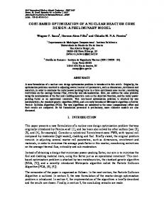
Fig. 1. Rectangular lattice with four unit cell parameters required for its specification. In a rectangular lattice, both the unit cells and the graph formed by joining unit cell centers with straight lines are rectangular. There are two lattice pitches, Px and Py, one each in the logical X and Y directions. The extent of a rectangular lattice is given by the number of unit cells in the X and Y directions, Nx and Ny. The total number of unit cells in a rectangular lattice is NxNy. The specification of unit cell types is as a vector of integer types; by convention, these integers identify unit cell types starting at the top left and proceeding right and down in the lattice. We place the origin of a rectangular lattice at the centroid of the top left cell. Fig. 1 shows an example specification of a rectangular lattice in these terms, defining its pitches, dimensions, and unit cell types. This method for specifying rectangular lattices is used as input to the tools described Section 3. Hexagonal, Symmetry = 1 Nrings = Nr = 3 P = 1.0 NTOT = 3Nr(Nr-1) + 1 = 19 Celltypes = ABC…
Fig. 2. Full hexagonal lattice with three unit cell parameters required for its specification.
Fig.3. Two symmetry types in a 60-degree lattice, HexVertex (left) and HexFlat (right). In a hexagonal lattice, the unit cells are hexagonal, while the lines joining unit cell centers form triangles. We restrict ourselves to a single hexagonal lattice pitch, P. The dimension of a 6
hexagonal lattice is indicated by the number of rings, Nr, formed around a central unit cell, with the central cell identified as the first ring. By convention, the central unit cell hexagon is oriented such that two of its vertices are placed on the +y and –y axes, and the +x and –x axes intersect two edges or “flats” of the unit cell. Fig. 2 shows a full 360-degree lattice with the required parameters describing the lattice. Lattices can also be specified for certain symmetry types for hexagonal lattices (symmetry cases for rectangular lattices can be specified using the same techniques as for a full lattice). Fig. 3 shows two types of 60-degree lattice, varying by whether a hexagon vertex or edge intersects the +x axis; Fig. 4 shows a 30-degree lattice, which has only one symmetry type. For more details on specifying these lattices and the parameters required, see [10].
Fig.4. A 120-degree lattice, which has only a single symmetry type.
3 A Three-Stage Workflow for Generating Reactor Core Models A reactor core model is produced by generating assembly models for each unique assembly type, then copying/moving these assembly models into place in a core lattice. Our approach uses a sequence of tools to accomplish these tasks, so that the user can manually adjust output of one tool and input of the next tool at each stage of the process. The workflow for running these tools is depicted in Figs. 5 and 6. The first stage of this process uses the AssyGen tool, which generates an assembly geometry based on a text input file. A reactor core assembly is a lattice of unit cells. Each unit cell has zero or more concentric cylindrical layers of material, cut from a background material defined for each unit cell or for the assembly as a whole. Unit cell shapes can also be imprinted on the background material, to more finely control the mesh in each unit cell. The assembly can be surrounded by one or more layers of duct wall material. Multiple pincell types can be defined, each with one or more concentric cylinders of material and a background material for the cell. The overall assembly model can be modified based on the Center, Rotate, and Section keywords, and mesh sizes can be specified by using the RadialMeshSize and AxialMeshSize keywords. Cylinders input for individual pin cells can be larger than the unit cell dimensions; these volumes will overlap neighboring pincell regions when present. In this case, a special keyword can be used to restrict these larger structures to the unit cell, such that they do not overlap neighboring regions. Empty pin cells can be specified in the assembly lattice by specifying a pre-defined “NULL” unit cell type, indicating that only background material (and structures from neighboring unit cells) 7
overlaps the cell. Parameters can be specified multiple times with varying Z-dimensions and material properties to create assembly models with axially varying properties. Example 6.2 demonstrates the model created using this option. For more details on the generation of assemblylevel models in this stage, see [10].
Fig. 5. First two stages of the geometry/mesh process, where AssyGen and CUBIT are executed for each assembly type. In the second stage of execution, the meshing script and geometry output from AssyGen are used by CUBIT to generate a mesh for that assembly type. This process of constructing assembly meshes, while somewhat automated, can be sensitive to mesh size input by the user. This problem is manifested particularly in the generation of unstructured quadrilateral meshes for the top surface in an assembly, which is cut by large numbers of cylindrical rods. To keep overall mesh sizes reasonable, analysts typically want one or two quadrilateral elements between fuel rods; however, meshing with such relatively coarse sizes (compared to the geometric features in the region) will often fail. This is one of the reasons for splitting the core mesh generation process into several steps: to allow user intervention midway through the process. The general solution for this type of failure would be either to make the mesh size finer (producing many more elements), or to perform geometry decomposition of the assembly top surface such that the resulting smaller, less-complex surfaces are meshable with more primitive algorithms. The only explicit requirement on the resulting mesh is that the mesh on outer boundaries of the assembly match that of neighboring assemblies, or of the interstices material in cases where assemblies do not completely fill the core space. Because CUBIT is a closed-source code, efforts are being made to support lattice-type mesh generation with the MeshKit library described in Section 4. For more details on the generation of assembly meshes, see [10]. In the final stage, shown in Fig. 6, the CoreGen tool reads an input file describing the arrangement of assemblies in the core lattice and locations of models for each assembly type, along with those meshes; this information is used to generate the overall core mesh. CoreGen also produces a makefile, which can be used to automatically rerun parts of the process affected by changes to any of the input files. CoreGen supports construction of full rectangular, full hexagonal, 60-degree hexagonal, and 30-degree hexagonal lattices. Two 60-degree hexagonal variants, HexVertex and HexFlat, are supported; these lattice types are described in Section 2. In several cases application 8
codes require surface boundary conditions on the entire core model. CoreGen allows specification of the entire- top, bottom and side surfaces of the core lattice as boundary conditions. This is achieved by using the NeumannSet keyword, it is followed by specification of ‘top’, ‘bot’ or ‘side’ and a unique integer NeumannSet Id. On the implementation side CoreGen uses the skinning operation in MOAB [11]. This operation gets the surface elements on the entire skin of the core, these are filtered to obtain top, bottom or side surface elements as required by the user in the output core model.
Fig. 6. Third stage of the geometry/mesh process, where CoreGen is executed 3.1 Geometry-only Models from CoreGen The input for the third stage of the process includes the list of assembly mesh files and their associated names, the placement of these assemblies in the core lattice, and a few parameters for the core model as a whole. In some cases, there is a need to generate geometric models for the corresponding core structure, for example in cases where the geometric model was needed as input to a different analysis code or meshing procedure. To meet this need, the CoreGen tool was modified to perform copy/move operations on geometry instead of mesh files. These modifications were relatively straightforward, since the core operations were already supported in the underlying geometry library (see Section 4 for a discussion of implementation). This capability will be useful for comparing the RGG-based process described here with meshing capabilities in other, non-open-source codes.
3.2 Support for Tetrahedral Assembly Mesh The process described here is well-suited to generating 2.5D extruded meshes, since the sides of a 2.5D mesh are always structured quadrilaterals, and those meshes are relatively easily matched between neighboring assemblies (assuming the proper interval constraints have been imposed on the boundaries of the side surfaces). However, in some cases tetrahedral meshes are desired. For 9
example, in some cases a core mesh will be combined with a mesh of the inlet/outlet plenums; these regions are more complex, having structures for flow distribution and pass-throughs for reactor control structures, and typically must be meshed using tetrahedra. In other cases, nonsymmetric features in prismatic fuel bundles, for example converging coolant channels in Very High Temperature Reactors (VHTRs), must be resolved, again using tetrahedral meshes.
Fig. 7. An axial Surface split along LoS and mesh from “Source Surface” flipped to “Target Surface” along LoS. Although tetrahedral meshes are far easier to generate for single-assembly meshes, they are actually a bit more difficult to incorporate into the lattice-based approach described here. In particular, where a structured quadrilateral mesh will be symmetric about a vertical bisection of the surface2, the side surfaces of a tetrahedral mesh will be composed of unstructured triangles, and therefore will not match up with neighboring assemblies. These meshes must be constrained such that matching is guaranteed. For rectangular and hexagonal unit cell types, the easiest constraint would be to match up opposite sides, yielding two (rectangular) or three (hexagonal) pairs of surfaces which would need to be assigned the same mesh. This would give translational symmetry within the core lattice; that is, assemblies could be translated to arbitrary unit cell positions in the lattice and be guaranteed to match the mesh in neighboring assemblies. However, there are several cases where rotational symmetry is desired or required, particularly for the partial-core symmetries shown in Fig. 5. Therefore, we choose to constrain the mesh on side surfaces such that they maintain both translational and rotational (about the axial direction) symmetry. We accomplish this by splitting each side surface, as shown in Fig. 7. A triangular mesh is generated for one of the resulting halves, and reflected across the split line to the other half. The meshes on these two surfaces are then copied to the other 3 (rectangular) or 5 (hexagonal) side surface pairs in the assembly. After this is done, the resulting assembly meshes will have translational and rotational symmetry across the core lattice.
2
Here we assume equal-spacing on the top and bottom edges bounding the surface. If biasing or
some other node placement strategy is used, extra steps will typically be required to ensure the mesh matches between neighboring assemblies. 10
This method for generating tetrahedral meshes is demonstrated in the example described in Section 6.3 of this paper.
3.3 Extension to a Four-Stage Process Using Extrusion In the three-stage process described above, 3D assembly models and meshes are generated then copy/moved into a core lattice. An alternative approach, where 2D assembly geometry and meshes are copy/moved into a 2D whole-core model, then extruded into a third direction, has also been developed. The advantage of this approach is that fewer mesh vertices need to be copied, moved, and evaluated during the mesh merging part of the third stage. Since mesh extrusion is a trivial thing to implement, this part of the calculation can also be implemented based on MOAB and specialized for this case, making the extrusion itself more efficient as well. This alternative approach was implemented and enabled by new keywords in the CoreGen text input. Results are discussed in Section 6.3 below.
3.4 Matching Meshes Between Assemblies The generation of core meshes using the methods described in this paper relies on matching the mesh between sometimes disparate assemblies that neighbor each other in the core lattice. Currently, AssyGen and CoreGen do not check for or explicitly enforce constraints that would guarantee that this matching would be possible. We see several remedies for this problem. First, in the case of 2.5D meshes with equal spacing along curves bounding the top surfaces of the assemblies, it may be sufficient to provide an additional keyword to the AssyGen input that constrains the number of intervals along those sides3. In this case, the user would be responsible for using the same value for this parameter in all assemblies to be combined into a core model, but this seems like a reasonable constraint. In the case of biased spacing, first the only allowable option that would guarantee rotational symmetry would be dual-biasing with the same bias factor on both ends. In that case, the same bias factor and number of intervals would need to be used in all assemblies, which again would seem like a reasonable constraint. In the case of tetrahedral meshes, we assume that surfaces with similar geometric and topological properties will be given the same mesh. For both hexahedral and tetrahedral meshes, the only way to absolutely guarantee that neighboring assembly meshes would match would be to explicitly specify the surface mesh to be used for all side surfaces of all assemblies. However, given the effort required to implement that capability, and for the user to specify that in a text-based input approach, we assert that at that point it is probably easier to abandon the dual lattice approach and mesh the entire core geometry in a fully general tool like CUBIT.
3
When just size is specified, the number of intervals may be changed during the “interval
assignment”, which is needed to guarantee all-quadrilateral meshability of the bounded surface. 11
4 Implementation The tools described in this paper rely on geometry and mesh libraries developed as part of the Interoperable Tools for Advanced Petascale Simulations (ITAPS) project. The Common Geometry Module (CGM) [12] provides functions for constructing, modifying, and querying geometric models in solid model-based and other formats. While CGM can evaluate geometry from several underlying geometry engines, this work relies mostly on ACIS [13], with an Open.Cascade-based [14] version also supported. Finite-element mesh and mesh-related data are stored in the MeshOriented datABase (MOAB)[11]. MOAB provides query, construction, and modification of finiteelement meshes, plus polygons and polyhedra. Mesh generation is performed by using a combination of tools. The CUBIT mesh generation toolkit [16] provides algorithms for both tetrahedral and hexahedral mesh generation. MeshKit, an open-source mesh generation library under development at Argonne National Laboratory, provides efficient algorithms for mesh copy/move/merge, extrude, and other algorithms [17]. CGM and MOAB are accessed through the ITAPS iGeom and iMesh interfaces, respectively. The iMesh concept of sets and tags is important to the implementation of these tools. A set is an arbitrary collection of entities and other sets; a tag is data annotating entities, sets, or the interface itself. The combination of sets and tags is a powerful mechanism used to describe boundary conditions, material types, and other types of metadata commonly found with mesh.
V4
V3
F
F
V3
V4
C F
F
V2 V1
V1
Side
Side
V2 Side
F V1 C
Fig. 8. Generation of an extruded mesh by copy/moving a single unit cell into four, then extruding axially.
5 Metadata Handling Typical simulations require not only a mesh, but also material, boundary condition, and other groupings of mesh entities. If these groupings are not handled during the copy/move process, the 12
resulting mesh will not be suitable for analysis. One way to approach this problem would be to code explicitly for each type of group. For example, the copy/move algorithm API would include functions for defining material groupings, and the implementation would know to propagate specified material groupings to new mesh. However, this approach is not extensible (that is, every new application-specific grouping would require modification to the algorithm API to handle that type of grouping), and unnecessarily pollutes the implementation of the basic meshing algorithm with application details. Instead, we approach this problem by defining abstractions for the various types of grouping behavior desired, with applications specifying the handling of specific types of groupings according to those abstractions. Because this behavior usually applies to how groupings are handled, we define behavior types according to the type of set they apply to. Three types of sets are defined: •
Copy sets: These are sets that get duplicated and populated with copies of entities in the original copy set.
•
Expand sets: These sets are expanded, that is, copies of entities are put into the same sets containing the entities being copied.
•
Extrude sets: These are sets whose contents are replaced with extruded versions of the original entities.
For a particular model, RGG could identify the specific sets designated as copy, expand, or extrude sets, and pass those sets to the copy algorithm. However, we have found that the process can be further simplified by having the application (in this case, RGG) specify sets in terms of the criteria by which those set types are identified. The criteria are specified in terms of the tags, and possibly the values of those tags, in the desired sets. We explain the three types of sets and the expected behavior by way of a simple example. Consider a simple unit cell, consisting of an inner circular surface, representing a fuel pin, and an outer material, representing a coolant region (see Fig. 8). Both surfaces are meshed, as are the bounding model edges and vertices. On this model, we have identified one group of elements in set “F”, corresponding to fuel, and another group as coolant set “C”. We have also identified a set of mesh faces as volume “V1”. Sets F and C are designated as “Expand” sets, that is, any copies of mesh faces in these sets will be added to those sets; in other words, the sets will expand to include copies of the contained faces. The set V1 is identified as a “Copy” set; any copies of the mesh faces in that set will be put into a copied set. Next, the pair of surfaces is copy/moved to get four pairs of surfaces, arranged in a square 2x2 grid. The F and C sets expand to include the corresponding face copies, while the V1 set is copied three times. Next, the sets of mesh edges bounding the collection are added to a set designated as “side”, and this set is identified as an “Extrude” set. In addition, the F, C, and V1-V4 sets are also identified as extrude sets. In the final operation, the eight surfaces are extruded into the 3rd dimension. In each extrude set, each entity is replaced with the next-higher-dimension entity or entities produced by the extraction. So, sets F, 13
C, and V1-V4 receive sets of hexahedra resulting from the extrusion of the quadrilaterals in the respective sets, while the “Side” set receives quadrilaterals, extruded from the edges originally in the set.
6 Examples In this section we present two examples; one a simple hexagonal assembly and the other a more complex core model.
6.1 Single Hexagonal Assembly Our first example, a single Very High Temperature Reactor (VHTR) assembly, has six pincell types, with three sizes of pins representing fuel, burnable poison, and coolant regions; a structure at the center describes a fuel handling hole, and a larger hole in the lower half of the assembly represents a control rod and guide tube. Empty pin cells are specified in cell positions surrounding these larger holes. The resulting geometric model is shown in Fig. 9 (left). We note that generating an all-quadrilateral mesh for the top surface of the block can be challenging because of closelypacked cylindrical pins, as discussed in Section 3 of this paper. The model generated by AssyGen was used as input to UNIC, a neutron transport code [18] developed at Argonne National Laboratory. Fig. 9 (right) shows the thermal neutron flux computed. The flux is much lower in the region of the large control rod and slightly lower around the six burnable poison pins (located at corners of the hexagonal assembly), as expected. Note that in this case a tetrahedral mesh was used, which was generated by the CUBIT journal file output by AssyGen.
Fig. 9. Hexagonal assembly geometry and mesh constructed by AssyGen (left); thermal neutron flux computed by the UNIC neutron transport calculation for this hexagonal assembly (right).
6.2 Axially Varying Seven Assembly Benchmark Problem
14
A benchmark problem is run for initializing the thermo-fluid fields prior to beginning fluid and neutronics multi-physics simulation. Unlike the example in Section 6.1, in this example the material properties vary in the axial direction and the core consist of seven assemblies. This problem is solved using STAR-CCM+. Each of the six axial fuel cells are separated by a small gap filled with helium coolant; Coolant flows at a uniform rate of 8.89 kg/s. Fig. 10 shows the horizontal view of the assembly, the pins include fuel coolant, graphite and poison rods. Upper and lower plenums are also modeled as shown in Fig. 11 (Coolant). Power output of the fuel is held uniform at 21.21MW. Fig. 12 shows dips in the temperature profile caused by coolant filled gap between the 6 fuel blocks. AssyGen creates axially varying geometries, and Coregen writes the output mesh in the STAR-CCM+ file format via the MOAB-STAR-CCM+ writer. The assembly geometry generated for this benchmark problem has 9483 geometric bodies; generation of the geometry using AssyGen and the hexahedral mesh using CUBIT takes 10mins and 15mins, respectively. CoreGen takes 10GB of RAM and 50minutes of clock time to create the seven assembly core model. The complete core model has 75M faces, 28M hexes and 40M vertices.
Fig. 10. Horizontal view of the seven assembly core model (left); a closeup of intersection of two assemblies.
Coolant
Graphite Block
Fuel
Fig. 11. Single assembly model showing axially varying material properties.
15
Fig.12. Temperature gradient in fuel pins.
Fig. 13. One sixth of a VHTR core model generated using CoreGen (left); a closeup of several assemblies in this model (right).
Fig. 14. Four assembly types produced by AssyGen. 6.3 Sixth core model, constructed without and with using extrusion. Fig. 13 shows a one sixth Very High Temperature Reactor (VHTR) core; this model was created using the three-stage process described in this paper. Fig. 14 shows four of the 11 assembly types used in this model. The model consists of ~12M hexahedral elements and 14M mesh vertices. The tools were run on a desktop Linux-based workstation with a clock speed of 2.5 GHz and 11.8 GB RAM. Using, the three-stage process without extrusion, it took 4 minutes to generate the
16
geometries using AssyGen, 5 minutes to create hexahedral assembly meshes using CUBIT (version 10.2), and 20 minutes to generate the core model using CoreGen. The same model was constructed using a four-stage process. First, two-dimensional assemblies were created using AssyGen; then, CUBIT was used to mesh these assemblies (with quadrilaterals); next, a two-dimensional core was generated using CoreGen; in the fourth stage of this process, the entire 2D core mesh was extruded into the third dimension. Using this extrusionbased approach required less than half the execution time of the 3-stage process. For the one-sixth core model shown in Fig. 13, the total execution time was reduced from 29 minutes to 15 minutes, or by almost 50%. This reduction was due primarily to the reduced number of vertices that needed to be copied, moved, and merged between assemblies during the CoreGen stage. For example, the number of vertices considered for merging was reduced from 162690 in the 3D process to only 9570 in the 2D CoreGen process. The minimum and maximum shape metrics for the VHTR mesh are 0.00125 and 0.00618, respectively. These metrics are quite low (normally, shape metric values above 0.2 are deemed acceptable). However, this is due to the high aspect ratio of the assemblies (each assembly is 7.93 meters in length but only about 37 cm across) and the resulting mesh.
6.4 Tetrahedral mesh example Fig. 15 shows a 7-assembly model meshed with tetrahedra. The number of mesh intervals along axial curves is intentionally set to a small number (two) to make the symmetry lines visible in the mesh. As discussed in Section 3.2, these symmetry lines are inserted on the model, and the side surface mesh reflected across that line of symmetry, to guarantee rotational symmetry in the side surface meshes. The shape quality metric [19] for this mesh has an average of 0.84 and a standard deviation of 0.16, with a minimum of 0.066; this low quality is a result of the low number of divisions along the axial length and the thin duct wall around each assembly. If the number of divisions axially is increased to 16 and the edge length requested is 0.022, the minimum shape metric increases to 0.292 (but the total number of elements increases 10-fold, to 3.1M elements for this model).
Fig. 15. 7-assembly model with tetrahedral mesh. 17
7 Conclusions An input-file-based methodology has been developed that can generate a lattice-based reactor core mesh with minimal user input. The methodology operates in three stages. First, assembly models of various types are generated by the AssyGen tool, using text-based input describing the content of pin cells, the arrangement of pin cells in the lattice, and the extent of the lattice and any surrounding material. The assembly model or models then are meshed with the CUBIT mesh generation toolkit, optionally based on a journal file output by AssyGen. After one or more assembly model meshes have been constructed, they are arranged in a core model using the CoreGen tool, again using text-based input. Although this approach is ideally suited for latticebased core geometries, it also offers flexibility to incorporate non-lattice-based features. The original three-stage approach for generating lattice-based models was extended in several ways from that reported in an earlier paper. First, an option was added to CoreGen for generating geometry-only models for the core. This addition was very straightforward due to existing support for copy/move operations in the CGM library. Generating whole-core geometric models will be useful for comparing our mesh generation process with that of other codes. Support for generating tetrahedral meshes with this three-stage process was also developed; the primary difficulty there was the careful application of surface splitting, mesh reflection, and mesh copying, to ensure both translational and rotational symmetry of mesh on the side surfaces of assemblies. We also demonstrated a four-stage process, wherein a 2D mesh model for the core is generated, followed by extrusion into the third dimension. This approach requires about half the execution time of the original three-stage process, due mostly to a large reduction in the number of vertices being compared for merging.
ACKNOWLEDGMENTS We thank M. A. Smith, A. Wollaber, and J. H. Thomas in the Nuclear Engineering Division at Argonne National Laboratory for helpful discussions and feedback for creating the input file language used in these tools. We also thank the Fathom group at Argonne, who maintain the libraries required by this tool. This work is sponsored by the U.S. Dept. of Energy Office of Nuclear Energy Nuclear Energy Advanced Modeling & Simulation (NEAMS) Program; by the U.S. Dept. of Energy Office of Scientific Computing Research, Office of Science, and by the US Department of Energy’s Scientific Discovery through Advanced Computing program, under Contract DE-AC02-06CH11357. REFERENCES 1. Sandia news notes (2005) http://www.cs.sandia.gov/newsnotes/2005newsnotes.html#Goodyear 2. S. Fung, A. Adler, and A. D. C. Chan (2010) “Using Dismesh as a mesh generating tool for EIT,” Journal of Physics, Conference Series. 18
3. J. R. Cebral and R. Lohner (1999) “From medical images to CFD meshes,” in Proc. 8th International Meshing Rountable, pp. 321-331. 4. B. K. Sony and M. H. Shih (1991) “TIGER: Turbomachinery Interactive Grid GenERation,” in Proc. Third International Conference of Numerical Grid Generation in CFD, Barcelona, Spain. 5. R. V. Chima (2008) TCGRID website, http://www.grc.nasa.gov/WWW/5810/rvc/tcgrid.htm 6. List of meshing software website http://www-users.informatik.rwth-aachen.de/~roberts/software.html 7. PSG2 / Serpent website (2010) http://montecarlo.vtt.fi/ 8. K.A. V. Riper (1993) “SABRINA: Three-dimensional geometry visualization code system,” PSR-242, ORNL-RSICC, Oak Ridge, TN. 9. G. Hansen and S. Owen (2008) “Mesh generation technology for nuclear reactor simulation; Barriers and opportunities,” Journal of Nuclear Engineering and Design. pp. 2590-2605. 10. T. J. Tautges and R. Jain, “Creating Geometry and Mesh Models for Nuclear Reactor Core Geometries Using a Lattice Hierarchy-Based Approach,” in Proceedings of the 19th International Meshing Roundtable, Springer Berlin Heidelberg, 2010, pp. 351-365. 11.T. J. Tautges, R. Meyers, K. Merkley, C. Stimpson, and C. Ernst, MOAB: A Mesh-Oriented Database. Sandia National Laboratories, 2004. 12. T. J. Tautges (2005) “CGM: A geometry interface for mesh generation, analysis and other applications,” Engineering with Computers, 17, pp. 486-490. 13. Spatial website (2010) http://www.spatial.com/ 14. Open CASCADE Technology website (2000-2010) http://www.opencascade.org. 15. C. Ollivier-Gooch, L. F. Diachin, M. S. Shephard, and T. Tautges (2007) “A languageindependent API for unstructured mesh access and manipulation,” in Proc. 21st International Symposium on High Performance Computing Systems and Applications, IEEE, p. 22 16. G. D. Sjaardema, T. J. Tautges, T .J. Wilson, S. J. Owen, T. D. Blacker, W. J. Bohnhoff, T. L. Edwards, J. R. Hipp, R. R. Lober, and S. A. Mitchell (1994) CUBIT mesh generation environment, volume 1: Users manual, Sandia National Laboratories, Albuquerque, NM. 17. MeshKit website (2010) http://trac.mcs.anl.gov/projects/fathom/browser/MeshKit 18. M. A. Smith, C. Rabiti, G. Palmiotti, D. Kaushik, A. Siegel, B. Smith, T. Tautges, and W. S. Yang (2007) “UNIC: Development of a new reactor physics analysis tool,” in Proc. Winter Meeting on International Conference on Making the Renaissance Real, American Nuclear Society, pp. 565-566. 19. P. M. Knupp (2001), “Algebraic mesh quality metrics”, SIAM J. Sci Comput, 23, pp. 193-218.
19
The submitted manuscript has been created by UChicago Argonne, LLC, Operator of Argonne National Laboratory ("Argonne"). Argonne, a U.S. Department of Energy Office of Science laboratory, is operated under Contract No. DE-AC02-06CH11357. The U.S. Government retains for itself, and others acting on its behalf, a paid-up nonexclusive, irrevocable worldwide license in said article to reproduce, prepare derivative works, distribute copies to the public, and perform publicly and display publicly, by or on behalf of the Government.
20