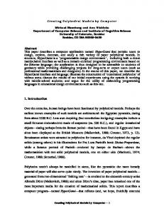
Creating Models of Truss Structures with Optimization Jeffrey Smith Carnegie Mellon University
Jessica Hodgins Carnegie Mellon University
Irving Oppenheim Carnegie Mellon University
Andrew Witkin Pixar Animation Studios
Abstract We present a method for designing truss structures, a common and complex category of buildings, using non-linear optimization. Truss structures are ubiquitous in the industrialized world, appearing as bridges, towers, roof supports and building exoskeletons, yet are complex enough that modeling them by hand is time consuming and tedious. We represent trusses as a set of rigid bars connected by pin joints, which may change location during optimization. By including the location of the joints as well as the strength of individual beams in our design variables, we can simultaneously optimize the geometry and the mass of structures. We present the details of our technique together with examples illustrating its use, including comparisons with real structures. CR Categories: I.3.5 [Computer Graphics]: Computational Geometry and Object Modeling—Physically based modeling; G.1.6 [Numerical Analysis]: Optimization—Nonlinear programming; G.1.6 [Numerical Analysis]: Optimization—Constrained optimization Keywords: Physically based modeling, truss structures, constrained optimization, nonlinear optimization
1
Introduction
A recurring challenge in the field of computer graphics is the creation of realistic models of complex man-made structures. The standard solution to this problem is to build these models by hand, but this approach is time consuming and, where reference images are not available, can be difficult to reconcile with a demand for visual realism. Our paper presents a method, based on practices in the field of structural engineering, to quickly create novel and physically realistic truss structures such as bridges and towers, using simple optimization techniques and a minimum of user effort. “Truss structures” is a broad category of man-made structures, including bridges (Figure 1), water towers, cranes, roof support trusses (Figure 10), building exoskeletons (Figure 2), and temporary construction frameworks. Trusses derive their utility and distinctive look from their simple construction: rod elements (beams) {jeffrey|jkh}@cs.cmu.edu,
[email protected],
[email protected]
Figure 1: A cantilever bridge generated by our software, compared with the Homestead bridge in Pittsburgh, Pennsylvania.
which exert only axial forces, connected concentrically with welded or bolted joints. These utilitarian structures are ubiquitous in the industrialized world and can be extremely complex and thus difficult to model. For example, the Eiffel Tower, perhaps the most famous truss structure in the world, contains over 15,000 girders connected at over 30,000 points [Harriss 1975] and even simpler structures, such as railroad bridges, routinely contain hundreds of members of varying lengths. Consequently, modeling of these structures by hand can be difficult and tedious, and an automated method of generating them is desirable.
1.1
Background
Very little has been published in the graphics literature on the problem of the automatic generation of man-made structures. While significant and successful work has been done in recre-
ating natural structures such as plants, the trunks and roots of trees, and corals and sponges (summarized in the review paper by Prusinkiewicz [1993]), these studies emphasize visual plausibility and morphogenetic realism over structural optimality. Parish and M¨uller recently described a system to generate cityscapes using L-systems [Parish and M¨uller 2001], but this research did not address the issue of generating individual buildings for particular purposes or optimality conditons. Computer-aided analysis of simple truss structures, coupled with graphic displays of deflection or changing stresses, has been used for educational purposes within the structural engineering [MacCallum and Hanna 1997] and architecture [Piccolotto and Rio 1995] communities, but these systems are not intended for the design of optimal structures. In the field of structural engineering, the use of numerical optimization techniques to aid design dates back to at least 1956 when linear programming was used to optimize frame structures based on plastic design theory [Heyman 1956]. Since then, extensive research has been done in the field of “structural synthesis,” as it is sometimes called, although its penetration into industry has been limited [Topping 1983; Haftka and Grandhi 1986]. Techniques in the structural engineering literature generally fall into three broad categories: geometry optimization, topology optimization, and cross-sectional optimization (also known as “size optimization”) [Kirsch 1989]. Cross-sectional optimization, the most heavily researched of these three techniques, assumes a fixed topology and geometry (the number of beams and joints, their connectivity, and locations) and finds the shape of the beams that will best, either in terms of mass or stiffness, support a given set of loads. The parameters of the structure that are changed during optimization, called the design variables, are properties that affect the cross-sectional area of a beam such as, for the common case of tubular elements, the radius and thickness of each tube. An example of this technique in practice is the design of the beams that are used to build utility transmission towers [Vanderplaats and Moses 1977], where savings of only a few hundred dollars in material costs, when multiplied by the thousands of towers needed for a new transmission route, can be a substantial gain. Topology optimization addresses the issues that size optimization ignores; it is concerned with the number and connectivity of the beams and joints, rather than their individual shape. Because structure topology is most easily represented by discrete variables, numerical techniques used for topology optimization are quite different from those used for continuous size and geometry optimization problems. Prior approaches to this problem have included genetic programming [Chapman et al. 1993], simulated annealing [Reddy and Cagan 1995], and “ground structure methods” wherein a highly connected grid of pin-joints is optimized by removing members based on stress limits [Hemp 1973; Pederson 1992]. A review of these discrete parameter optimization problems in structural engineering can be found in Kirsch [1989]. The third category of structural optimization, geometry optimization, lies between the extremes of size and topology optimization. The goal of geometry optimization is to refine the position, strength and, to some extent, the topology of a truss structure. Because these problems are highly non-linear, geometry optimization does not have as lengthy a history as size and topology optimization [Topping 1983]. A common approach, called “multi-level design,” frames the problem as an iterative process wherein the continuous design variables are optimized in one pass, and then the topology is changed on a second pass [Spillers 1975]. It is from this literature that we draw the inspiration for our work. For civil and mechanical engineers, the ultimate goal of structural optimization is a highly accurate modeling of reality. Thus, common to all these techniques, no matter how different their implementations, is a desire for strict physical accuracy. In the field
Figure 2: A cooling tower at a steel mill created by our software compared with an existing tower. From left to right: a real cooling tower, our synthesized tower, and the same model with the obstacle constraints shown. of computer graphics, however, we are often just as concerned with the speed of a solution and its visual impact as with its accuracy. For example, although important to structural engineers, optimizing the cross-sections of the members used to build a bridge would be considered wasted effort in the typical computer graphics application, as the subtle differences between different shapes of beams are hardly noticeable from cinematic distances. Thus, rather than being concerned only with our model’s approximation to reality, we are interested in optimizing the geometry and topology of truss structures with the goals of speed, user control and physical realism.
2
Representing Truss Structures
Truss structures consist of rigid beams, pin-connected at joints, exerting axial forces only. This simple form allows us to represent trusses as a connected set of three-dimensional particles where every beam has exactly two end-points, and joints can accommodate any number of beams. In our model, the pin-joints are classified into three types: free joints, loads, and anchors. Anchors are points where beams are joined to the earth, and thus are always in force balance. Loads are points at which external loads are being applied, e.g. the weight of vehicles on a bridge. Lastly, free joints are pin joints where beams connect but which are not in contact with the earth and have no external loads.
2.1
Constructing the Model
Before solving for an optimal truss structure, we must have a clear idea of what purpose we want the structure to serve. For example, a bridge must support some minimum weight along its span, the Eiffel Tower must support observation decks, and roof trusses need to support the roofing material. We model these support requirements as loads, which are placed by the user. Although most structural loads are continuous (e.g. a planar roadbed), appoximating loading as a set of discrete load-points is standard practice within the civil and structural engineering disciplines [Hibbeler 1998]. In addition to having external loads, every truss structure must also be supported at one or more points by the ground. For real structures, the location of these anchors is influenced by topography, geology, and the economics of a particular site, but for our modeling purposes their positions are specified by the user. After placement of the anchors and loads, a rich set of free joints is automatically added and highly connected to all three sets of
3
Optimizing Truss Structures
The most important property of any structure, truss or not, is that it be stable; i.e. not fall down. For a truss structure to be considered stable, none of the joints can be out of force balance. Because our model consists of rigid beams exerting axial forces only, we can describe the forces acting on any joint i as: ~l j λj ~ k l k j=1 Bi
~F (~λ ) = ~gm + ∑ i i
(1)
j
Figure 3: From top to bottom: the data specified by the user (loads are depicted as green spheres and anchors as white cones); the free joints added by the software above the loads; the automatically generated initial connections (beams). This structure was the initial guess used to create the bridge shown in Figure 4.
where λ j is the workless force being exerted by beam j, ~λ is the vector of these forces for all beams, ~g is the gravity vector, mi is the mass of joint i, Bi is the number of beams attached to joint i, and ~l is the vector pointing from one end of beam j to the other (the j direction of this vector is not important as long as it is consistent). Given an objective function G (usually the total mass, but perhaps containing other terms), we can optimize a truss structure subject to stability constraints by solving the following problem: min s.t.
G(~q) ~F (~q) = 0 i
i = 1...NJ
(2)
where NJ is the number of joints and ~q is the vector of design variables. If we wish to do simple cross-sectional optimization, this design vector is merely ~λ . If we wish to solve the more interesting geometry optimization problem, we also include the positions of all the free joints in ~q (see Section 3.2 for more details). In order to avoid physically meaningless solutions, we should also constrain the maximum force that any member can exert: kλ j k ≤ λmax
Figure 4: A typical railroad bridge and similar truss bridge designed by our software.
joints (see Figure 3). Specifically, our software generates free joints on a regular three-dimensional grid defined by the locations and spacings of the load and anchor points. Currently, our user interface asks the user to provide the number of vertical “layers” of free joints and whether these joints are initially placed above or below the loads (for example, they are placed above the road in Figure 3). In addition to this rectilinear placement, we also experimented with random placement of the free joints, distributing them in a spherical or cubic volume surrounding the loads and anchors. We found that random placement did not affect the quality of the final results, but could greatly increase the time needed for convergence. After generating the free joints, the software automatically makes connections between all three sets of joints, usually connecting each joint to its nearest neighbors using a simple O(N 2 ) algorithm. Note that during optimization, beams may change strength and position, but new beams cannot be added. In this sense, we are using a ground structure technique, as described in Hemp [1973]. The initial structure does not need to be practical or even stable; it is merely used as a starting point for the optimization problem.
j = 1...NB
(3)
where NB is the total number of beams. We constrain the absolute value of λ j because the sign of the workless force will be positive when the beam is under compression and negative when the beam is under tension. In equation 1, we approximate the mass of a joint mi as half the masses of the beams that connect to it plus, in the case of load joints, whatever external loads may be applied at that joint. Although in reality the mass of a truss structure (exclusive of the externally applied loads) is in its beams rather than its pin joints, this “lumping approximation” is standard practice in structural engineering and is considered valid as long as the overall structure is significantly larger than any component member [Hibbeler 1998]. This assumption reduces the number of force balance constraints by a factor of two or more, depending on the connectivity of the structure, as well as allowing us to model members as ideal rigid beams.
3.1
Mass Functions
For a given structural material, the mass of a beam is a function of its shape (length and cross-section). Under tension, the required cross-sectional area of a truss member scales linearly with the force the member exerts [Popov 1998]. Therefore, the volume of a beam under tension will be a linear function of length and force and, assuming a constant material density, so will the mass mT : mT = −kT λ j k~l j k
(4)
where kT is a scaling factor determined by the density and tensile strength of the material being modeled, k~l j k is the length of beam j, and λ j is the workless force it exerts (note that λ j here will be negative because the beam is in tension).
Adding these variables to the optimization problem does not change the form of the equations we have derived, but for numerical stability we now also constrain the lengths of all the beams to be above some small value: min s.t.
Figure 5: A depiction of Euler buckling under a compressive load.
Under compression, long slender beams are subject to a mode of failure known as Euler buckling, wherein compressive forces can cause a beam to bend out of true and ultimately fail (see Figure 5). The maximum axial compressive force (FE ) that can be supported by a beam before it undergoes Euler buckling is governed by the following equation: FE =
π 2 Er2 A π 2 EI = k~l j k2 k~l j k2
(5)
where k~l j k is the length of beam j, I is its area moment of inertia, and A is its cross-sectional area. E is the Young’s Modulus of the material being modeled and r is the radius of gyration, which describes the way in which the area of a cross-section is distributed around its centroidal axis. Because the cross-sectional area of a member is proportional to the square of r, we can rewrite equation 5 in terms of A and r as A2 ∝
FE k~l j k2 π 2E
(6)
Because we wish to use beams with minimum mass, λ j (for a given beam j) will be equal to FE and our approximation of the mass function under compression is q mC = ρA j k~l j k = kC λ j k~l j k2 (7) where ρ is the density of the material, k~l j k is the length of beam j, and λ j is the workless force being exerted by the beam. kC is a scaling factor determined by ρ and the constants in equation 6. Assuming the structures are made of steel I-beams, and using units of meters and kilograms, we use the values of 5 × 10⁻⁶ for kT and 1.5×10⁻⁵ for kC in equations 4 and 7 respectively. Because we plan to do continuous optimization, we wish to avoid any discontinuities in the mass function and thus we use a nonlinear blending function between mT and mC centered around λ j = 0 to smooth the transition.
3.2
Cross-Sectional and Geometry Optimization
Assuming that the objective function G(~q) in equation 2 is merely a sum of the masses of the joints, and that the vector of design variables ~q consists only of ~λ , we can use the equations developed in the last section to perform a simple version of size optimization. Solving this non-linear, constrained optimization problem will give us, for a fixed geometry, the minimum mass structure that is strong enough to support its own weight in addition to the user-specified external loads. We are interested, however, in the more useful geometry optimization problem, where both the strengths of the beams and the geometry of the overall structure can be changed. To allow the simultaneous optimization of the sizing and geometry variables, we add the positions of the free joints to the vector of design variables, ~q. We do not add the anchor or load positions to the design vector because the locations of these two types of joints are set by the user.
G(~q) ~F (~q) = 0 i kλ j k ≤ λmax k~l j k ≥ lmin
i = 1...NJ j = 1...NB j = 1...NB
(8)
where lmin was set to 0.1 meters in the examples reported here. Because the optimization algorithm we use (sequential quadratic programming, described in detail in Gill [1981]) handles inequality constraints efficiently, these length constraints add minimal cost to the solution of the problem. Similar to the methods discussed in Pederson [1992], we use a multilevel design algorithm consisting of two steps. First, we solve the optimization problem described in equation 8. Having found a feasible (if not yet globally optimal) structure, the system then merges any pairs of joints that are connected to one another by a beam that is at the minimum allowable length, because these two joints are now essentially operating as one. The system could also, if we wanted, eliminate beams that are exerting little force (i.e. those with small kλ j k), as they are not actively helping to support the loads. However, we prefer to leave such “useless” beams in the model so as to leave open more topology options for future iterations. After this topology-cleaning step, the results are examined by the user and, if they are not satisfactory for either mass or aesthetic reasons, the optimization is run again using this new structure as the starting point. In practice, we have found that a single iteration almost always gave us the structures we desired, and never did it take more than three or four iterations of the complete cycle to yield an appealing final result.
3.3
Objective and Constraint Functions
Although the procedure outlined above generates good results, there are many situations in which we want a more sophisticated modeling of the physics or more control over the final results. Constrained optimization techniques allow us to add intuitive “control knobs” to the system very easily. For example, in addition to constraints on the minimum length of beams, we can also impose constraints on the maximum length. These constraints imitate the real-world difficulty of manufacturing and shipping long beams. (Due to state regulations on truck flatbeds, girders over 48 feet are not easily shipped in North America.) Other changes or additions we have made to the objective and constraint functions include: minimizing the total length of beams (rather than mass), preferentially using tensile members (cables) over compressive members, and symmetry constraints, which couple the position of certain joints to each other in order to derive symmetric forms. Another particularly useful class of constraint functions are “obstacle avoidance” constraints, which forbid the placement of joints or beams within certain volumes. In this paper, we have used two different types of obstacle constraints: one-sided planar and spherical constraints. One-sided planar constraints are used to keep joints and beams in some particular half-volume of space; for example to keep the truss-work below the deck of the bridge shown in Figure 7. Implementation of this constraint is simple: given a point on the plane ~r and a normal ~n pointing to the volume that joints are allowed to be in, we constrain the distance from the free joints ~pi to this plane with NJ new constraints: (~pi −~r) ·~n ≥ 0
i = 1...NJ
(9)
Figure 7: A bridge with all trusswork underneath the deck. Figure 6: From left to right: initial structure, tripod solution, derrick solution. Similarly, to keep the beams and joints outside of a spherical volume, we add a constraint on each beam that the distance between the center of this sphere and the beam (a line segment) must be be greater than or equal to some radius R. This distance formula may be found in geometry textbooks, such as Spanier [1987]. For optimization purposes, we approximated the gradients of this function with a finite-difference method. The primary use of obstacle constraints is to allow the user to “sculpt” the final structure intuitively while preserving realism, but they can also serve to produce novel structures by creating local optima. Figure 6 shows, from left to right, an initial structure, infeasible because it violates the obstacle avoidance constraint, and two designs produced as solutions from slightly different (random) initial guesses for ~λ . In each image, the red sphere is the volume to be avoided, the green sphere at the top is the load that must be supported, and the cylinders are the beams, colored cyan or tan depending on whether they are in compression or tension. The anchors are located at the three points where the structure touches the ground. The middle, tripod solution hangs the mass on a tensile member (a cable) from the apex of a pyramid, and the derrick solution on the right supports the mass in a much more complex way (this solution has a mass about 3 times that of the tripod). Both of these solutions are valid and both exist as real designs for simple winches and cranes. Although it is a general concern that nonlinear optimizations can become trapped in sub-optimal local solutions, in our experience this has not been a problem. When, as in the above example, the system produces a locally optimal design, we have found that a few additional iterations of our algorithm are sufficient to find a much better optimum.
4
Results
We have described a simple, physically motivated model for the rapid design and optimization of models of truss structures. The following examples illustrate the output of this work and demonstrate the realistic and novel results that can be generated.
4.1
Bridges
Some of the most frequently seen truss structures are bridges. Strong and easy to build, truss bridges appear in a variety of shapes and sizes, depending on their use. A common type of truss bridge, called a Warren truss, is shown in Figure 4 with a photo of a real railroad bridge. The volume above the deck (the surface along which vehicles pass) was kept clear in this example by using constraints to limit the movement of the free joints to vertical planes. The initial guess to generate this bridge was created automatically from thirty user-specified points (the loads and anchors), shown in Figure 3. From this description of the problem, the system automatically added 22 free joints (one above each load point) and connected each of these to their eight nearest neighbors, resulting in a problem with 228 variables (22 free points and 163 beams). The
Figure 8: A perspective and side view of a through-deck cantilever bridge.
final bridge design consists of 48 joints and 144 beams, some of the particles and members having merged or been eliminated during the topology-cleaning step. Similar procedures were used to generate the initial guesses for all of our results. Using this same initial structure, but with constraints that no material may be placed above the deck, we generated a second bridge, shown in Figure 7. Note that the trusswork under the deck has converged to a single, thick spine. This spine is more conservative of materials than the rectilinear trusswork in Figure 4, but in the earlier case the constraints to keep the joints in vertical planes prevented it from arriving at this solution. Another type of bridge, a cantilever truss, is shown in Figure 1. As with the bridge shown in Figure 7, the cantilever bridge was constrained to have no material above the deck, and the joints were further constrained to move in vertical planes only. However, the addition of a third set of anchor joints in the middle of the span has significantly influenced the final design of this problem. This bridge is shown with a real bridge of the same design: the Homestead High Level Bridge in Pittsburgh, Pennsylvania. The bridge in Figure 8 was generated with the same starting point and the same objective function as that in Figure 1, but without the “clear deck” and vertical-plane constraints. Removal of these constraints has allowed the structure to converge to a significantly different solution, called a through-deck geometry.
4.2
Eiffel Tower
A tall tower, similar to the upper two-thirds of the Eiffel Tower is shown in Figure 9. This tower was optimized from an initial rectilinear set of joints and beams, automatically generated from eight user-specified points (the four anchor sites and a four loads at the top). We concentrated on the top two-thirds of the Tower because the design of the bottom third is dominated by aesthetic demands. Similarly, the observation decks, also ornamental, were not sythesized.
4.5
Timing Information
Sequential quadratic programming, relying as it does on the iterative solution of quadratic sub-problems, is a robust and fast method for optimizing non-linear equations. Even with complicated problems containing thousands of variables and non-linear constraints the total time to optimize any of the above examples from autogenerated initial guesses varied between tens of seconds and less than fifteen minutes on a 275MHz R10000 SGI Octane. Specifying the anchor and load points and the locations of obstacles (if any) rarely took more than a few minutes and with better user-interface design this time could be significantly reduced. For comparison, we timed an expert user of Maya as he constructed duplicates of the cooling tower (Figure 2), the Warren truss bridge (Figure 4) and the tower shown in Figure 9 from source photographs of real structures. We found that modeling these structures at a comparable level of detail by hand took an hour for the cooling tower, an hour and a half for the bridge and almost three hours for the Eiffel Tower. Although informal, this experiment showed that our method has the potential to speed up the construction of models of truss structures enormously, while simultaneously guaranteeing physical realism. Figure 9: Our trusswork tower, compared with a detail of the Eiffel Tower. Because they are ornamental and not structural, the observation decks are not included in our tower.
Figure 10: Three types of roof trusses: from left to right, cambered Fink, composite Warren, and Scissors. Illustrations of real trusses are shown at the top of each column. The lower two trusses in each column were generated with our software.
4.3
Roof Trusses
The frameworks used to support the roofs of buildings are perhaps the most common truss constructions. We have generated three different types of roof trusses for two different roof pitches. In Figure 10 we show each category of truss (cambered Fink, composite Warren, and Scissors) in its own column, at the top of which is an illustration of a real example. For a given pitch, all three types of trusses were generated from the the same initial geometry. The variation in the results is due to different objective functions: total mass (cambered Fink and Scissors) and total length of beams (composite Warren), and different roof mass (the Scissors trusses have a roof that weighs twice as much as the other two types of trusses).
4.4
Michell Truss
The Michell Truss is a well-known minimum-weight planar truss designed to support a single load with anchors placed on a circle in the same plane Although impractical because of the varying lengths and curved beams needed for an optimal solution, the Michell truss has been a topic of study and a standard problem for structural optimization work for nearly a century. We have reproduced the Michell truss with our system, starting from a grid-like initial guess and arriving at a solution very close to the analytical optimum (Figure 11).
5
Summary and Discussion
We have described a system for representing and optimizing trusses, a common and visually complex category of man-made structures. By representing the joints of the truss as movable points, and the links between them as scalable beams, we have framed the design as a non-linear optimization problem, which allows the use of powerful numerical techniques. Furthermore, by altering the mass functions of the beams, the objective function, and the constraints, we can alter the design process and easily generate a variety of interesting structures. Other than the location of anchors and loads, the factor that we found to have the largest effect on the final results was the use of obstacle avoidance constraints. Placement of these constraints is a powerful way of encouraging the production of certain shapes, such as the volume inside a cooling tower or the clear traffic deck on a railroad bridge. Not surprisingly, we also found that the number of free joints added during the initial model construction could affect the look of the final structure. However, this effect was largely one of increasing the detail of the truss-work, rather than fundamentally changing the final shape. The initial positions of the free joints, however, made little difference to the final designs, although they could affect the amount of time required for the optimization. In cases where the initial positions did make a difference, it was generally the result of constraints (such as obstacle avoidance) creating a “barrier” to the movement of free joints during optimization and thus creating local minima. In our experience, however, a few additional iterations of the algorithm were sufficient to get out of these local minima and find a global solution. We also found that beyond some minimum number of beams per joint (three or four), additional connections to more distant joints had a negligible effect on the final designs. We attribute this lack of impact to two factors. First, because we are minimizing the total mass of the structure (or occasionally only the total length of all members), shorter beams connected to closer joints will be used more readily than longer ones, especially if they are under compression. Secondly, by allowing unused beams to “fade away” as the force they exert drops to zero, initial structures with many beams per joint can become equivalent to structures with fewer beams per joint, allowing both more and less complex initial structures to converge to the same answer. Although successful at capturing the geometric and topological complexity of truss structures, our work does not account for all
Figure 11: From left to right: The initial structure from which we began the optimization, our final design, and an optimal Michell truss after an illustration in Michell [1904]. The red sphere on the left of each image is an obstacle (on the surface of which are the anchors), and the green sphere on the right is the load which must be supported. Gravity points down.
the details of true truss design. For example, a better objective function would calculate the actual cost of construction, including variables such as connection costs (the cost to attach beams to a joint) and the cost of anchors, which varies depending on terrain and the force they must transmit to the ground. Nor does our model explicitly include stress limits in the materials being modeled (although the constants kT and kC in equations 4 and 7 are an implicit approximation). Similarly, a more complex column formula than the simplified Euler buckling formula, such as those described in Popov[1998], might capture more nuances of real design. True structural engineering must also take into account an envelope of possible load forces acting on a structure, not a single set as we have implemented. In each of these cases, our approximations were made not for technical reasons (for example, load envelopes could be handled with multi-objective optimization techniques, and stress limits with more inequality constraints), but rather because the visual detail they add is not commensurate with the added complexity and expense of the solution. Eventually, we would like to be able to include more abstract aesthetic criteria in the objective function. Our current system incorporates the concepts of minimal mass and symmetry (via constraints), but many elements of compelling design are based on less easily quantifiable concepts such as “harmony,” the visual weight of a structure, and use of familiar geometric forms. Because our technique is fast enough for user guidance, implementing even a crude approximation to these qualitative architectural ideals would allow users more flexibility in design and the ability to create more imaginative structures while still guaranteeing their physical realism.
H ARRISS , J. 1975. The Tallest Tower – Eiffel and the Belle Epoque. Houghton Mifflin. H EMP, W. 1973. Optimum Structures. Clarendon. H EYMAN , J. 1956. Design of beams and frames for minimum material consumption. Quarterly of Applied Mathematics 8, 373–381. H IBBELER , R. 1998. Structural Analysis, fourth ed. Prentice Hall. K IRSCH , U. 1989. Optimal topologies of structures. Applied Mechanics Reviews 42, 8, 223–238. M AC C ALLUM , C., AND H ANNA , R. 1997. Deflect: A computer aided learning package for teaching structural design. In Proceedings of Education in Computer Aided Architectural Design in Europe. M ICHELL , A. 1904. The limits of economy of material in frame structures. Philosophical Magazine 8, 589–597. ¨ PARISH , Y. I. H., AND M ULLER , P. 2001. Procedural modeling of cities. In Proceedings of SIGGRAPH 2001, Computer Graphics Proceedings, Annual Conference Series, 301–308. P EDERSON , P. 1992. Topology optimization of three dimensional trusses. In Topology Designs of Structures, NATO ASI Series – NATO Advanced Research Workshop, Kluwer Academic Publishers, 19–30. P ICCOLOTTO , M., AND R IO , O. 1995. Design education with computers. In Proceedings of ACADIA 95: Computing in Design, 285–299. P OPOV, E. 1998. Engineering Mechanics of Solids. Prentice Hall. P RUSINKIEWICZ , P. 1993. Modeling and visualization of biological structures. In Proceeding of Graphics Interface, 128–137. R EDDY, G., AND C AGAN , J. 1995. An improved shape annealing algorithm for truss topology. ASME Journal of Mechanical Design 117, 2A, 315–321. S PANIER , J., AND O LDHAM , K. 1987. An Atlas of Functions. Hemisphere. S PILLERS , W. 1975. Iterative Structural Design. North Holland Publishing Co.
Acknowledgements We would like to thank Joel Heires for helping us with the Maya modelling tests. The photo of the Homestead Hilevel Bridge in Figure 1 is Copyright 2002 Pittsburgh Post-Gazette Archives. All rights reserved. Reprinted with permission. The photo of the steelmill cooling tower in Figure 2 is Copyright 2002 Bernd and Hilla Becher. All rights reserved. The photo of the bridge in Figure 4 is Copyright 2002 Bruce S. Cridlebaugh. All rights reserved.
References C HAPMAN , C., S AITOU , K., AND JAKIELA , M. 1993. Genetic algorithms as an approach to configuration and topology design. In Advances in Design Automation, vol. 65, ASME, 485–498. H AFTKA , R. T., AND G RANDHI , R. V. 1986. Structural shape optimization—a survey. Computer Methods in Applied Mechanics and Engineering 57, 91–106.
T OPPING , B. 1983. Shape optimization of skeletal structures: A review. Journal of Structural Engineering 109, 1933–1951. VANDERPLAATS , G., AND M OSES , F. 1977. Automated optimal geometry design of structures. Journal of the Structural Division of the American Society of Civil Engineers 98, ST3 (March). W RIGHT, M., AND G ILL , P. 1981. Practical Optimization. Academic Press.