Eight IEEE Workshop on Practical Issues in Building Sensor Network Applications 2013
CREST: An Epoch-Oriented Routing Control Plane for Low-Power and Lossy Networks James Pope Robert Simon Department of Computer Science and C4I Center George Mason University, Fairfax, VA 22030
[email protected],
[email protected] Abstract—There has been much recent interest in deploying IP-enabled routing and management protocols within Low-Power and Lossy Networks (LLN). For instance, the Routing Protocol for LLNs (RPL) forms a directed acyclic graph from which a routing tree can be selected. RPL is designed to dynamically modify routes in response to varying network conditions. However, many performance-sensitive LLN applications require stable routing trees with fixed homogeneous or heterogeneous transmission rates over defined time intervals. For these applications we introduce the CREST: Coordinated Routing for Epochbased Stable Tree framework. CREST provides a LLN and IPfriendly routing control plane for supporting this application class. CREST is designed to supplement, rather than replace, LLN routing protocols such as RPL or CTP. We describe our implementation of CREST in the Contiki operating system. We also present a performance analysis for a utility maximization application using the framework comparing epoch-based protocols to an RPL approach. Our results show that the epoch-based protocols consistently deliver higher utility levels.
I. I NTRODUCTION New generations of wireless networks designed to support Smart Grid applications [1], [2], Industrial Networks [3] and Building and Home Automation [4] systems are now being deployed. These wireless systems are populated by resource constrained nodes, have unreliable communication links and low data rates, and are referred to as Low-Power Lossy Networks (LLNs). Traditional routing protocols fail to address the operating characteristics within a LLN environment [5]. To address this problem the IETF has defined the IPv6 based Routing Protocol for Low-Power and Lossy Networks (RPL) [6], specifically designed for LLN operation. RPL defines a general purpose architectural framework for tree-based routing management, with an emphasis on node to sink communication. Path selection is achieved using a flexibly defined objective function to rank link and tree quality. These objective functions can use a number of proposed metrics, such as hop count or ETX, the estimated number of transmissions. An important class of LLN applications cannot be directly supported by RPL routing mechanisms. This class includes performance sensitive applications that require system-wide coordinated energy budgeting and management decisions [7] or industrial and control systems that use TDMA or packet scheduling at the link layer [8]. The systems that support these applications are typically epoch-based [9]. The epoch is used to ensure both a stable routing tree and fixed (homogenous or heterogenous) per-node transmission rates. This stability
978-1-4799-0540-9/13/$31.00 ©2013 IEEE
is used, for instance, to set energy budgets or assign node packet transmissions to different time slots. One advantage of an epoch-based WSN is that control and message overhead can be reduced, since routing and transmission rate decisions are typically made only at the start or finish of an epoch. Current LLN techniques such as RPL or CTP [10] do not directly support epoch-based decision making. To address the above shortfall this paper presents the CREST framework for epoch-based wireless sensor networks. CREST stands for Coordinated Routing for Epoch-based Stable Trees, reflecting the fact that the routing topology does not change during the epoch. The design philosophy of CREST is to use whatever underlying LLN routing protocol is available to collect and disseminate basic routing and topology information. Stability during each epoch is enforced by a basestation triggered and broadcast algorithm called Radiate [11]. In effect, CREST establishes a logically separate network control plane. Similar to the approach suggested in [6], CREST is designed to accept several routing objective functions. As a proof of concept, we have implemented a number of energy-based objective functions which seek to improve network utility. CREST selects the routing tree and enforces the rate assignment on an epoch by epoch basis. At the start of each epoch CREST calculates several possible tree based routing options and presents them to the application. The application selects its desired rate assignments and returns them to CREST. This information is delivered to the network by CREST via the Radiate broadcast protocol. We have implemented CREST using the Contiki operating system [12]. We have also defined four routing objective functions for use in LLNs that require energy-budgeting. We compared CREST and our objective functions against several other approaches, including a RPL-only and a naive greedy routing mechanism. In particular, we were interested in judging relative performance in terms of network utility, packet delivery and message protocol overhead. Our results indicate that these epoch-based protocols implemented within the framework offer superior performance in terms of network utility and packet delivery ratios, while introducing a minimal amount of overhead. This paper proceeds as follows: we first provide some background and related work in the areas of epoch-based applications and LLN routing. We then describe the CREST
128
Eight IEEE Workshop on Practical Issues in Building Sensor Network Applications 2013
architecture and its relationship to the LLN routing layer and the application. Next, we discuss the implementation of CREST and the Radiate broadcast protocol. Following that we present the results of a performance evaluation where we implemented a utility maximizing application and compared epoch-based protocols using the CREST framework to a RPLonly approach. Finally, we offer some observations and discuss future work. II. BACKGROUND AND R ELATED W ORK Our work targets resource constrained Low-Power and Lossy Networks [5]. Our particular focus is on LLNs that are configured into a tree-based topology, with a powerful gateway or base station at the sink. The nodes in the tree report their readings upwards towards the sink. We first describe LLN applications that benefit from an epoch-based network management approach, and then discuss related work in LLN routing. A. Epoch-based applications We say that a LLN application is epoch-based if it fixes the routing tree and the transmission rate of each node during an interval of time. An epoch oriented approach is often indicated if the application requires a high degree of stability in order to ensure consistent and predictable performance, something that can be difficult to achieve in an LLN environment. Certain applications, such as data aggregation, make the semantic assumption that the routing tree is stable during some system activity [13]. Other applications are also best supported by epoch-like approaches. For instance, systems that provide network Quality-of-Service (QoS) support through data link transmission policies fall into this category. In LLN systems, QoS link layer support can be provided via a time-slotted approach such as TDMA. Protocols that fall into this category include the work presented in [14] and Wireless Hart [8]. Another technique for QoS support is via packet scheduling algorithms. Examples here include MMSPEED [15] and QoSMAC [16]. None of these approaches are directly supported by current LLN techniques. Another important class of epoch-based LLN applications are systems that combine energy-harvesting and energy budgeting with performance sensitive communication requirements. For instance, Zhang, et al. [17] present a rate assignment algorithm known to be optimal given a routing tree, energy budget assignment, and monotonically increasing utility function. Epoch-based energy allocation algorithms for energy-harvesting sensor networks are also presented in [7], [9], [18]. These approaches seek to distribute energy over future epochs within minimum and maximum storage constraints. They also assume the availability of a stable routing tree that is externally produced. Section V shows a proof-ofconcept CREST implementation of an epoch oriented energy budget application. B. LLN routing frameworks There has been a substantial amount of research in routing protocols for LLNs such as Wireless Sensor Networks. See
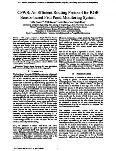
Fig. 1.
CREST Architecture
[19] for a survey of sensor network routing protocols that include many-to-one tree-based protocols. Important examples of tree-based routing techniques include CTP [10], Hydro [20], [21], and RPL [6]. The Hydro approach defines a hydrid tree routing protocol that routes traffic towards the sink using distributed methods and downwards using a centralized approach. RPL, which supports IPv6, collects data via routes established using a distributed protocol. Using a centralized algorithm, RPL also supports one-to-many and point-to-point communication. None of these approaches are designed to support an epoch-based route assignment. There has also been a substantial amount of research in designing routing protocols that achieve an application objective. For instance, Yi Cui, et al. [22] present a utility-based routing algorithm to maximize network lifetime. Other approaches attempt to minimize energy consumption [23]. In industrial networks gradient based approaches are often used to produce tree-based routing assignments [24]. These approaches are application specific, require specialized routing subsystems and are not immediately compatible with current IETF efforts. III. CREST A RCHITECTURE The CREST Architecture is depicted in Figure 1 with six steps during the epoch. Each epoch is defined by an Initialization phase, comprised of steps 1-5, and an Acquisition phase, comprised of step 6. CREST provides epoch-oriented routing services to the application. It interfaces with the underlying LLN routing protocol for topological information. Network routing and application decisions, such as rate assignments or packet scheduling, are performed at the sink node. Each node in the network runs the Radiate protocol. The following sections discuss the interfaces between each of the components.
129
Eight IEEE Workshop on Practical Issues in Building Sensor Network Applications 2013
A. CREST Control and Data Planes The architecture uses a separate control and data plane. The control plane consists of collecting and disseminating routing information. The data plane is formed by the disseminated routes, along which the data packets are sent to the sink. The routes used to manage the network may take different paths than the actual data messages. Data messages are restricted to only taking the assigned route providing a stable routing tree. The nodes receive the assigned route information from the control plane and send messages along the indicated route until the epoch expires and the process begins again. The control plane paths can dynamically change according to the associated LLN routing protocol. The initialization phase uses the control plane and the acquisition phase uses the data plane. As noted above, supporting epoch-based applications requires that CREST freezes routing paths during the data plane phase. LLN systems exhibit variable levels of per node wireless transmission impairments that should require changes to the routing tree. CREST accounts for this by recalculating the data plane tree for each epoch invocation. CREST always has the most up-to-date information about the network state because the LLN routing protocol continually executes its monitoring activity, even during data plane operation. Further, changing the length of the epoch allows CREST to increase its sensitivity to networks that have a higher or lower degree of packet loss and variable rates of transmission impairments. B. CREST Design CREST is implemented at the sink (also called the root) of the tree. The application can be co-located on the sink or on a host attached to the sink. The framework is designed to provide a relatively simple interaction with applications interested in determining stable route and rate assignments in an epoch-based manner. Using the associated LLN routing management system, CREST collects the neighbor and link state information for each node along with the node’s metrics for the epoch (step 1 in Figure 1). CREST gathers this information in the form of a directed acyclic graph (DAG). The DAG is an annotated data structure that contains the connectivity and node/link metrics for each node. Application specific node metrics are also supported. These could be, for instance, energy available for the epoch or other information such as encryption capability, available sensors, etc. These capabilities can be used for route decisions in support of application needs. In step 2, the DAG is sent to the application, which assigns values, such as transmission rate or scheduling policies, to each of the nodes. These values can be chosen using a variety of objectives and algorithms depending on the applications’ needs. The application returns the values to CREST in step 4 which then disseminates to each of the nodes in the network as part of step 5. Step 6 is the relatively longer period during which the nodes send messages at the assigned rates along the specified routes. The framework interfaces with the routing protocol at two different points - the sink and the remote nodes. At the sink the framework collects the basic routing information
from the routing protocol using a many-to-one communication protocol. CREST aggregates the information and transforms it into a DAG. Each node has desired metrics including neighbor information. This information is then presented to the epoch-based application. After route and rate assignments, the framework broadcasts the information using a one-to-many protocol. CREST also interacts with the routing protocol at remote nodes by implementing neighbor messages unicast from the nodes to the sink and again receiving the route and rate assignment messages from the sink. Our implementation uses the Contiki unicast capability and Radiate to receive the assignments. IV. CREST I MPLEMENTATION As noted, the architecture allows different routing layers and applications with various objectives. We assume that the time to collect, make routing and rate decisions, and disseminate is smaller than the epoch. An RPL implementation (Contiki RPL) was modified to implement the epoch-based decision intervals and provide the DAG and node/link state information to the framework. RPL’s default (minimizing expected transmissions) objective function is used to create the control plane to collect information and Radiate is used to disseminate information. The assigned routes are then used to send data messages forming the data plane. The epoch-based application was implemented on a host attached to the sink and communicated with the framework via a serial protocol. We now describe implementation details and the routing objective functions we have developed. A. Epoch Timeline At the beginning of each epoch, the nodes repeatedly send their neighbor and node/link information to the sink in a neighbor message using RPL (step 1 Figure 1). The number of neighbor messages and length for the initialization phase are configurable. This allows the sink to gather enough information to form a directed graph. At the end of the initialization phase, the sink calculates the routes and rate assignments. The assignments and rates are sent to each node via the Radiate protocol (step 5 in Figure 1). The sink sets a timer to expire after the acquisition duration plus initialization duration. The acquisition phase starts when a node receives a Radiate message. The nodes set their timer to the acquisition duration and send at the rate specified with added jitter. The jitter is added to avoid collisions between neighboring nodes’ transmissions. When the acquisition duration timer expires the nodes automatically start sending their neighbor and energy information to the sink signifying a new epoch. Note that using the sink’s assigned acquisition duration keeps all nodes synchronized with respect to the epoch. Figure 2 shows an example of the epoch timeline for node 5. At the beginning of the epoch, the node sends two neighbor messages to the sink via node 3, which is the control plane route (in this case, formed by an RPL objective function). The framework receives the assignment information and broadcasts
130
Eight IEEE Workshop on Practical Issues in Building Sensor Network Applications 2013
Algorithm 1 Digraph Transformation into DAG 1: //Input: Digraph G, each node has n.neighborSet 2: //Output: DAG Sink-rooted directed acyclic graph 3: GR = reverse(G) 4: //For each node sets the distance to the sink ni .distance 5: BF S(GR ) 6: for each ni ∈ {GR − sink} do 7: for each p ∈ ni .neighborSet do 8: if p.distance >= ni .distance then 9: remove edge n to p from ni .neighborSet 10: end if 11: end for 12: end for 13: DAG = reverse(GR ) 14: return DAG
Fig. 2.
Implementation, Example Epoch Timeline for Node 5
using Radiate. After node 5 receives the message, it then sends data messages to the sink at the proper rate using node 2, which is the data plane route (step 6 in Figure 1). This continues until the epoch expires and the process repeats. B. Digraph Transformation Algorithm The purpose of the algorithm is to remove cycles from the collected directed graph (digraph) to form a sink-rooted DAG. The algorithm is described in terms of an application using energy budgets to assign routes and rates. At the beginning of the epoch CREST collects each node’s neighbor messages containing the node’s energy available to use during the epoch and neighbor connectivity information. CREST keeps this information in a digraph. The digraph is stored with each node pointing to an adjacency list of edges. The digraph created may have loops as RPL allows nodes to point to neighbors farther or the same distance from the sink than themselves. Each node ni in the digraph has the following attributes. • distance - hop-count distance to the sink • energy - budget in message transmissions per epoch • rate - rate in messages per epoch • route - route to send data messages • neighborSet - set of immediate (one-hop) neighbors Algorithm 1 shows the process to transform the digraph into a DAG. The algorithm prunes the digraph of edges that cause loops. For each node, the algorithm removes the node’s neighbors that are farther away than the node itself as determined by hop count. The hop count distance is calculated by running a breadth first search (BFS) on the digraph. The digraph is passed to the reverse function (omitted) at line 3 where all edges’ direction is flipped (weights are not modified). This allows the BFS algorithm to determine the distance from the sink to each node of the reversed digraph GR . At line 5, hop
count distances are set by the BFS function on the passed GR . At line 6, the resulting graph is then enumerated comparing each node’s distance to that of its neighbors and only keeping those that are closer to the sink (line 9 performs the pruning). The framework calls the digraph transformation function and the returned sink-rooted DAG, returned at line 14, is then passed to the application in step 2 of Figure 1. C. CREST Application Programming Interface To allow different implementations with minimal effort, we define two application programming interfaces (API), one used by the application at the sink and one used by each of the nodes in the network. The API abstracts the framework from the underlying implementation. The interaction between the client and API occurs at the sink node (or host attached to the sink). The sink has one timer to indicate when the epoch starts and ends. The sink API passes the neighbor and node/link information for each node to the application which returns the route and rate assignment to the framework to disseminate (steps 2-5 in Figure 1). The node API consists of a callback function that listens for Radiate messages. The framework calls this function delivering the RadiateMessage containing the rate/route information for the node. The function determines the period between data messages to achieve the assigned rate and starts two timers one to sample and send messages and another to know when the acquisition phase ends. The node then starts sending at the specified rate using the assigned route (steps 5 in Figure 1). D. Radiate Broadcast Mechanism CREST requires a one-to-many mechanism so that the routes and rates for the epoch can be efficiently distributed to the nodes. The RPL specification provides the destination advertisement object (DAO) messages for sending down the collection tree. A one-to-many mechanism could be to unicast from the sink to each node using the DAO formed routes. However, we chose to implement a broadcast/flooding algorithm called Radiate using the simple-udp interface. This approach was taken as it is more reliable.
131
Eight IEEE Workshop on Practical Issues in Building Sensor Network Applications 2013
Using Radiate, the sink node initiates a flood by incrementing a sequence number. It then broadcasts to its neighbors using the link-local multicast mechanism (address ff02::1). All neighbors receive the message, check the sequence number and, if different, randomly (to reduce chances of a collision) schedule a broadcast to their neighbors with the same message. Eventually all nodes will receive the broadcast with the latest sequence number and the re-broadcasting stops. In a fashion similar to the Trickle decay mechanism [25], Radiate repeats additional broadcasts, for reliability purposes, at increasing intervals until a max number is reached, after which no more broadcasts are transmitted. We use the following heuristic to reduce these broadcasts: when a node overhears a neighbor rebroadcast the same version, the timer increases as though a broadcast had been sent. This results in nodes that overhear many of the same broadcasts to likely only send once and those at the edge to sent just a few broadcasts. E. Route Assignment Algorithms CREST can be used to implement various objective functions for route selection. We have defined and implemented several such functions that take energy budgets into account, suitable for epoch-based applications. An energy budget is used to decide how much energy can be expended for all of a nodes actions during a time period, including computation, communication and sensor or actuator actions [7], [18]. Using CREST we implemented the following objective functions: 1) Maximum Budget Assignment: This algorithm, called MBA, uses a simple greedy approach that selects the immediate parent that has the most energy allocated for the epoch. The advantage of this technique is its simplicity and low overhead, although it may to lead to high energy parents being overloaded. 2) Maximum Ratio Assignment: This algorithm, called MRA, selects the parent with the maximum energy budget to number of children ratio. The idea is to spread the children among the parents to those with more energy having proportionally more children. The algorithm needs to avoid evaluating a node and then later adding children to it as this may invalidate previous decisions. To prevent this situation, we sort the nodes descending by hop-count and id and then evaluate the tree bottom-up. An issue concerning this approach is that the immediate parent of a node may appear to be better but its ancestor may be a bottleneck and the node should have chosen an alternative route. 3) Maximum Route Ratio Assignment: To ameliorate the MRA issue, the MRRA algorithm examines the routes to the sink to avoid bottlenecks. The MRA algorithm is first executed and then each node’s immediate parents’ routes are examined. For each route the minimum energy budget to descendants ratio is determined. The algorithm selects the immediate parent whose route has the maximum ratio (i.e. the route that is least constrained). Of the algorithms presented, it is expected that MRRA would produce higher utility as it selects routes that more evenly distribute loads.
4) RPL-only Assignment: During initialization, the framework uses RPL to form the control plane and during the acquisition phase this route assignment algorithm simply uses the same RPL routes (i.e. data and control messages use the same route). This is termed ”RPL-only” to distinguish that it is the route assignment evaluation versus the protocol used to implement the framework. Since the control plane mechanism is used, routes may change dynamically during the epoch resulting in data messages taking different routes within the same epoch. RPL defines two objective functions, rpl-of0 that seeks to minimize hop-count and rpl-of-etx that seeks to minimize expected transmissions. RPL-only is configured to minimize expected transmissions. Due to these routes changing during the epoch, heterogeneous rate assignment was not applicable, so a homogeneous rate assignment was used instead. The utility produced by RPL-only is expected to be a function of the rate. Lower rates deliver fewer messages resulting in expected lower utility. Higher rates may produce more utility but eventually constraints might lead to less optimal routes for utility. However, minimizing expected transmissions inherently diverts away from overloaded routes (essentially load balancing), so it may perform well with regard to utility. V. E VALUATION We conducted a series of performance evaluations using CREST and an epoch oriented application. The purpose of this evaluation was to access the overhead associated with CREST, and to determine how well CREST supported the applications objectives and semantics. The algorithms were evaluated using network utility, protocol overhead, and packet delivery ratio (PDR). We compared the epoch-based approaches to an RPLonly approach. The evaluation used a number of different route and rate assignment algorithms. The route assignment was performed first followed by the rate assignment. A. Network Utility Evaluating routing protocols using throughput and delay are common for traditional networks. For many LLN applications these metrics are not particularly useful. High throughput is not normally required and minimizing delay generally does not benefit the application. Alternatively, systems can be evaluated according to the benefit provided to users of the system, typically quantified using a utility function. The utility function is defined for each node and the input is usually the number of node messages received at the sink. The evaluation sums each node’s utility to provide an overall network utility used to evaluate each protocol. The node’s utility function can be linear, however, the approach taken here models a diminishing return (each additional sample is valued less than the previous). This is common for these types of systems, similarly used by Moser, et al. [9] and Aydin, et al. [26], though does punish strong contributors. This measure also captures the need to sense across as much of the network as possible. To see this, consider the following example: given 5 nodes sending a total of 15 messages, the
132
Eight IEEE Workshop on Practical Issues in Building Sensor Network Applications 2013
function should produce higher utility {3, 3, 3, 3, 3} versus {7, 2, 2, 2, 2}. Following a standard approach for utility for each epoch: let mn be the received at the sink for node n, N be in the network excluding the sink, and network utility is as follows: U T ILe =
for rate assignments determining network number of messages the number of nodes e the epoch. The the
N 1 X log (mn ) N n=1 2
This formulation is also compatible with the rate assignment algorithm, explained next. B. Rate Assignment Algorithm The evaluation used the M AX U T ILIT Y algorithm [17] for assigning heterogeneous rates. The objective of the M AX U T ILIT Y algorithm is to increase utility via rate assignment given a routing tree and energy budget for each node. Considering some minimum rate and a concave, monotonically increasing function, the authors show that optimal utility can be achieved when rates are assigned as equal as the constraints allow. The MBA, MRA, and MRRA results all used the algorithm for the evaluation. The M AX U T ILIT Y algorithm recursively determines the bottleneck nodes in the given routing tree, removes their descendants from the tree, and assigns a rate to each of the descendants. Given a minimum rate for each node, the bottleneck node is determined by the node whose energy is the most constrained given the number of descendants. Each descendant is assigned the same rate which is simply the bottleneck’s energy divided by the number of descendants. C. Energy Budget Assignment We assume an energy assignment algorithm, similar to those presented in the related work [7], [9], [18], that allocates the maximum available energy consumption that can be used during the epoch. Infeasible scenarios can occur, for example, when a minimum rate is required and a parent does not have sufficient energy for its descendants to achieve this rate. To simplify our evaluation and to avoid infeasible scenarios, we assign minimum energy plus some random (uniform distribution) amount for each node to use during the epoch. The minimum amount is a function of the network size and the duration of the epoch. For evaluation purposes, a layer is inserted into the network stack which counts each time a frame transmission occurs and decrements the energy budget for the epoch. When the energy reaches zero, the layer drops the frame which includes control, data, and RPL messages. The following formulation is used where N is the number of nodes in the network, elen is the epoch length in minutes, and messagesEpochn is the maximum number of messages that node n can use during the epoch. base = N × elen messagesEpochn = base + (rand()%base)
Fig. 3.
6x6 Topology
D. Simulation Environment The Swedish Institute for Computer Science has developed the Contiki OS [12] - Wireless Sensor Network operating system. Contiki implements a subset of the 6LoWPAN [27] and RPL specifications. The simulation environment was based on ContikiOS Simulator (Cooja). Cooja provides simulated hardware components for a number of hardware platforms. We chose the Zolertia Z1 [28] which uses a MSP430 processor and CC2420 radio [29]. The platform provided approximately 52kB of program memory and 8k of random access memory. The applications are simple senders and a sink. The sender tries to send 48 bytes of sensor payload data to the sink with a specified rate in data messages/epoch. The rate is dynamic for the CREST implementations and fixed for RPL-only with rates between 25-175 data messages/epoch at intervals of 25. For simplicity of analysis we disable radio duty cycling. We used the Unit Disk Graph Medium Distance Loss with a 50 meter transmission range and a 100 meter interference range. The transmit and receive probabilities were set to 1.0, so any medium losses are associated with congestion. This enables the analysis to focus on routing related losses versus other types of impairments. The simulations used two topologies, 16 (4x4) nodes and 36 (6x6) in a grid-like pattern (shown in Figure 3). The nodes are on average 30 meters apart, however, each node is randomly placed within a proportionally smaller square area. This introduces some variability while still maintaining a connected network. The udp-sink is placed in the middle of the network allowing for more feeder nodes. Each epoch was specified to be 10 minutes in length. Each simulation was run for 60 minutes for a total of 6 epochs. Within each epoch we specified a 1 minute initialization phase with 9 minutes for acquisition phase. The initialization phase was specified to send a neighbor message randomly every 10 seconds for a total of 6 neighbor messages. The results for
133
Eight IEEE Workshop on Practical Issues in Building Sensor Network Applications 2013
PRD, UTIL, and Overhead are each computed per epoch and then the average is taken over all the epochs. E. Results
the tradeoff between epoch support and a purely dynamic approach. However, the overhead ratio does decrease markedly as the rate increases to a less than 5% overhead after a rate of 125.
The packet delivery ratio and network utility (UTIL) are calculated for each epoch. Though the two may seem correlated there are counterexamples in the results (e.g. PDR goes up but UTIL goes down). For instance, two nodes with 5 out of 10 ({5/10, 5/10}) messages received at the sink result in a UTIL of 4.64 and a PDR of 50%, whereas 8 and 3 out of 10 ({8/10, 3/10}) result in a UTIL of 4.58 and a PDR of 55%. For this class of applications, ”success” is measured by UTIL and not PDR. Note that we are comparing protocols with heterogeneous rates versus a protocol with homogeneous rates where the independent variable is the specific homogeneous rate. The heterogeneous rate protocols (MRA, MRRA, MBA) were simulated once and the dependent variable (PDR and UTIL) are simply repeated for each rate. The homogeneous rate protocol (RPL) was run once for each rate and the corresponding dependent variables plotted accordingly. 1) Overhead: The framework overhead in message complexity consists of the end-to-end neighbor messages and the Radiate broadcast messages. We estimate the neighbor messages to be the number of times the node sends multiplied by the number of hops necessary to reach the sink. Each node simply counts the number of times that it broadcasts a Radiate message. These two values are then added to produce the total message overhead for the framework. The neighbor messages are essentially constant for each epoch. The framework also imposes a time overhead with the initialization phase of 1 minute which, in this case, is 10% overhead. However, the epoch period can be reasonably increased to reduce this percentage. The formulation for determining overhead is as follows.
Overheade =
N 1 X (#radiaten +#neighborn ×hopcountn ) N n=1
To provide a comparison instead of number results, we compare the framework overhead to the number of data messages sent to the sink to provide a ratio. Because the overhead is relatively constant (not a function of the rate), we would expect the ratio to decrease as the rate increases. 2) 4x4 Results: Figures 4 and 5 show the packet delivery ratio and utility for the 4x4 topology. MRRA and MRA are essentially the same and slightly outperform MBA. For low rates, RPL has a better PDR but lower utility as would be expected. As the rate increases the results show PDR decreasing and utility increasing. At a rate 125 it appears to reach an ideal point with respect to PDR and UTIL, however, at rate 150 the utility and delivery ratio both drop off sharply. Averaging over repeated simulations may smooth this and the decrease is less profound for rate 175. Figure 6 shows the overhead for each rate. Initially, for a rate of only 25, the overhead is 24%, which demonstrates
134
Fig. 4.
PDR 4x4
Fig. 5.
UTIL 4x4
Fig. 6.
Overhead 4x4
Eight IEEE Workshop on Practical Issues in Building Sensor Network Applications 2013
Fig. 7.
PDR 6x6
Fig. 9.
Overhead 6x6 TABLE I 4 X 4 TABLE R ESULTS
Protocol MRRA MRA MBA RPL-only
PDR% 96 96 96 80
(min) UTIL (max) 6.72 6.65 6.61 (3.84) 5.37 (6.74)
TABLE II 6 X 6 TABLE R ESULTS
Fig. 8.
Protocol MRRA MRA MBA RPL-only
UTIL 6x6
3) 6x6 Results: Figures 7 and 8 show the packet delivery ratio and utility for the 6x6 topology. MRRA now shows a modest increase in utility of about 0.25 compared to MRA and MBA. RPL-only also shows similar behavior as the 4x4 topology with the ideal UTIL point now at a rate of 100. As the rate increases the results show PDR decreasing and utility increasing. At rate 100 it appears to reach an ideal point with respect to PDR and UTIL, however, thereafter degrades. Figure 9 shows the overhead for each rate. The results are similar to the 4x4 topology and low rates incur a high overhead ratio and then abate as the rate increases. 4) Application Support: The numerical results for PDR and UTIL are shown for the topologies in Tables I and II. The UTIL min, mean, and max are shown for RPL-only. Shown in Figure 5, the RPL-only min occurs at rate 175 and the max occurs at rate 125. Figure 8 shows the min occurring at rate 150 and the max at 100. The disadvantage of RPL-only, where each node is assigned the same rate, is that the rate resulting in better utility has to be discovered for each epoch while the other approaches adapt each node’s rate to achieve higher utility. Except for the noted rates, the CREST protocols produced higher utility results with less than 5% overhead on average. Though we did not show, we note that the RPL overhead messages (DIO/DAO neighbor advertisements/solicitations) can be
PDR% 78 79 84 68
(min) UTIL (max) 6.52 6.34 6.26 (4.10) 5.22 (6.39)
eliminated during the acquisition phase. The low overhead is very small for most of the rates examined demonstrating the applicability to LLNs. For RPL rates higher than 175 we do not report results. The simulations were partially invalid as the routing protocol(s) failed to properly form the network for most of the epochs. This also suggests that epoch-oriented services such as CREST require relatively reliable collect and disseminate mechanisms. The results clearly demonstrate that the CREST framework can be implemented to achieve application objectives requiring epoch-based, stable trees using dynamic routing protocols. VI. C ONCLUSION We have shown that providing a stable, epoch-based routing framework over RPL can expand its applicability. Using CREST, we demonstrated how a designer might implement epoch-based, utility maximizing objectives with non epochbased routing protocols. The CREST architecture allows a wider range of applications to be deployable using nascent IPv6 standards for LLNs.
135
Eight IEEE Workshop on Practical Issues in Building Sensor Network Applications 2013
ACKNOWLEDGMENT This work is supported by NSF under grants CNS-1116122 and CNS-1205453.
[17]
R EFERENCES [1] V. Gungor, B. Lu, and G. Hancke, “Opportunities and challenges of wireless sensor networks in smart grid,” Industrial Electronics, IEEE Transactions on, vol. 57, no. 10, 2010. [2] S. Depuru, L. Wang, V. Devabhaktuni, and N. Gudi, “Smart meters for power grid - challenges, issues, advantages and status,” in Power Systems Conference and Exposition (PSCE), 2011 IEEE/PES, 2011, Pages 1–7. [3] A. Willig, “Recent and emerging topics in wireless industrial communications: A selection,” Industrial Informatics, IEEE Transactions on, vol. 4, no. 2, Pages 102–124, 2008. [4] D.-M. Han and J.-H. Lim, “Smart home energy management system using ieee 802.15.4 and zigbee,” Consumer Electronics, IEEE Transactions on, vol. 56, no. 3, Pages 1403–1410, 2010. [5] P. Levis, A. Tavakoli, and S. Dawson-Haggerty, Overview of Existing Routing Protocols for Low Power and Lossy Networks, IETF Draft Report, 2009. [6] “RPL: IPv6 Routing Protocol for Low-Power and Lossy Networks,” RFC 6550 (Proposed Standard), Internet Engineering Task Force, Mar. 2012. [7] D. K. Noh, L. Wang, Y. Yang, H. K. Le, and T. Abdelzaher, “Minimum variance energy allocation for a solar-powered sensor system,” in Proceedings of the 5th IEEE International Conference on Distributed Computing in Sensor Systems, ser. DCOSS ’09. Berlin, Heidelberg: Springer-Verlag, 2009, Pages 44–57. [8] J. Song, S. Han, A. Mok, D. Chen, M. Lucas, and M. Nixon, “Wirelesshart: Applying wireless technology in real-time industrial process control,” in Real-Time and Embedded Technology and Applications Symposium, 2008. RTAS ’08. IEEE, 2008, Pages 377–386. [9] C. Moser, J.-J. Chen, and L. Thiele, “Reward maximization for embedded systems with renewable energies,” in IEEE International Conference on Embedded and Real-Time Computing Systems and Applications, 2008. RTCSA ’08. 14th, 2008, Pages 247 –256. [10] O. Gnawali, R. Fonseca, K. Jamieson, D. Moss, and P. Levis, “Collection Tree Protocol.” Conference On Embedded Networked Sensor Systems, 2009, Pages 1–14. [11] J. Pope and R. Simon, “The impact of packet fragmentation on internet-of-things enabled systems,” in 35th International Conference on Information Technology Interfaces, Jun. 2013. ¨ [12] A. Dunkels, F. Osterlind, and Z. He, “An adaptive communication architecture for wireless sensor networks,” in Proceedings of the 5th international conference on Embedded networked sensor systems, ser. SenSys ’07. New York, NY, USA: ACM, 2007, Pages 335–349. [13] S. Madden, M. J. Franklin, J. M. Hellerstein, and W. Hong, “Tag: a tiny aggregation service for ad-hoc sensor networks,” SIGOPS Oper. Syst. Rev., vol. 36, no. SI, Pages 131–146, Dec. 2002. [14] S. Munir, “Addressing burstiness for reliable communication and latency bound generation in wireless sensor networks,” in Proceedings of the 9th ACM/IEEE International Conference on Information Processing in Sensor Networks. New York, NY, USA: ACM, 2010, Pages 303–314. [15] E. Felemban, C.-G. Lee, and E. Ekici, “Mmspeed: multipath multi-speed protocol for qos guarantee of reliability and. timeliness in wireless sensor networks,” Mobile Computing, IEEE Transactions on, vol. 5, no. 6, Pages 738 – 754, june 2006. [16] P. Suriyachai, U. Roedig, and A. Scott, “Implementation of a mac protocol for qos support in wireless sensor networks,”
[18]
[19]
[20] [21]
[22]
[23]
[24]
[25] [26]
[27]
[28] [29]
136
in Pervasive Computing and Communications, 2009. PerCom 2009. IEEE International Conference on, march 2009, Pages 1 –6. B. Zhang, R. Simon, and H. Aydin, “Maximum utility rate allocation for energy harvesting wireless sensor networks,” in Proceedings of the 14th ACM international conference on Modeling, analysis and simulation of wireless and mobile systems, ser. MSWiM ’11. New York, NY, USA: ACM, 2011, Pages 7–16. D. K. Noh and K. Kang, “A practical flow control scheme considering optimal energy allocation in solar-powered wsns,” in Computer Communications and Networks, 2009. ICCCN 2009. Proceedings of 18th Internatonal Conference on, aug. 2009, Pages 1 –6. T. Watteyne, A. Molinaro, M. Richichi, and M. Dohler, “From MANET To IETF ROLL Standardization: A Paradigm Shift in WSN Routing Protocols.” IEEE Communications Surveys and Tutorials, 2010. S. Dawson-Haggerty, A. Tavakoli, P. Dutta, and D. Culler, “Hydro: A hybrid routing protocol for sensor networks,” Berkeley, California, USA, 2010, Pages 1–12. A. Tavakoli, “Exporing a centralized/distributed hydrid routing protocol for low power wireless networks and large scale datacenters,” in IPSN 2010. Electrical Engineering and Computer Sciences, University of California at Berkeley, Nov. 2009, Pages 1–96. Y. Cui, Y. Xue, and K. Nahrstedt, “A utility-based distributed maximum lifetime routing algorithm for wireless networks,” Vehicular Technology, IEEE Transactions on, vol. 55, no. 3, Pages 797 –805, may 2006. C. Schurgers and M. Srivastava, “Energy efficient routing in wireless sensor networks,” in Military Communications Conference, 2001. MILCOM 2001. Communications for NetworkCentric Operations: Creating the Information Force. IEEE, vol. 1, 2001, Pages 357–361 vol.1. P. T. A. Quang and D.-S. Kim, “Enhancing real-time delivery of gradient routing for industrial wireless sensor networks,” Industrial Informatics, IEEE Transactions on, vol. 8, no. 1, Pages 61–68, 2012. P. Levis, T. Clausen, J. Hui, O. Gnawali, and J. Ko, “The Trickle Algorithm,” RFC 6206 (Proposed Standard), Internet Engineering Task Force, Mar. 2011. H. Aydin, R. Melhem, D. Mosse, and P. Mejia-Alvarez, “Optimal reward-based scheduling for periodic real-time tasks,” Computers, IEEE Transactions on, vol. 50, no. 2, Pages 111– 130, 2001. G. Montenegro, N. Kushalnagar, J. Hui, and D. Culler, “Transmission of IPv6 Packets over IEEE 802.15.4 Networks,” RFC 4944 (Proposed Standard), Internet Engineering Task Force, Sep. 2007. Z1, Zolertia, www.zolertia.com/products/z1, 2010. CC2420, Texas Instruments, www.ti.com/product/cc2420, 2006.