www.advmat.de
COMMUNICATION
www.MaterialsViews.com
Critical Thickness of SiO2 Coating Layer on Core@Shell Bulk@Nanowire Si Anode Materials for Li-Ion Batteries Soojin Sim, Pilgun Oh, Soojin Park, and Jaephil Cho* For medium and large energy-storage devices, lithium-ion batteries require high capacity, high rate capability, and high energy-density electrode materials. To meet these requirements, silicon is being considered as the most promising candidate among the anode materials because of its high theoretical gravimetric and volumetric capacities of ca. 3700 mA h g−1 and 2200 mA h cm−3, respectively.[1] However, the most challenging problem associated with Si is its drastic volume change of >400% during lithium alloy/dealloy reactions, which results in capacity loss with cycling.[2] To overcome this problem, various approaches, such as active/inactive composites,[3–12] morphology controls (nanowires,[13–18] nanotubes,[19–21] core-shell structures,[22–29] porous structure,[30–33] etc.) and polymer/organic binders,[34–37] have been reported. In a Si anode, a carbon coating layer can be introduced to minimize the side reactions with the electrolytes and increase the electrical conductivity to achieve high rate capability. In addition, once Si particles are pulverized during cycling, broken carbon layers which are dispersed between the particles are believed to retain the conduction pathway during the initial cycles.[38] For instance, our previous study[31] clearly supports this effect of carbon coating; after carbon coating on bulk Si, its capacity retention was similar to that of the bare electrode after cycling. However, the capacity retention of the coated Si up to 10 cycles was higher than that of the bare sample, which indicates that fragments of fractured carbon layer may retain the electrical conductivity between the pulverized Si particles in the composite electrode. However, in the end, the capacity retention of the coated Si sample was identical to that of the bare electrode, which shows that accelerated formation of a new solid electrolyte interface (SEI) layer on the pulverized Si particles may result in the catastrophic failure of the electrical contact between fragments. Recently, Cui and co-workers showed that volume expansion could be suppressed during the first lithiation of a Si nanowire (NW) with a native SiO2 surface-coating layer of about 3.4 nm thickness and diameter of less than ca. 50 nm, using ex situ TEM experiments.[39] However, once the NW diameter exceeded >100 nm, its coating layer did not contribute to suppression of the volume expansion. Suppression of the volume expansion by using metal oxide (SiO2, ZrO2, Al2O3, and TiO2) coating in the electrode materials was first reported by Cho et al.,[40] S. Sim, P. Oh, Prof. S. Park, Prof. J. Cho Interdisciplinary School of Green Energy Ulsan National Institute of Science & Technology (UNIST) Ulsan, S. Korea, 689–798 E-mail:
[email protected]
DOI: 10.1002/adma.201301454
4498
wileyonlinelibrary.com
who proposed that, depending on the coating material and the coating thickness on the cathode, the volume expansion degree of the cathode material can be controlled. However, too thick a coating layer diminishes the specific capacity and Coulombic efficiency. In terms of volume change of the anode material, the change of a composite electrode after cycling should be considered because repetitive cycles could lead to more drastic change than is the case with single particles. Another important issue for Si anodes is the electrode density. For instance, fully porous Si particles with a carbon coating layer of about 10–20 nm demonstrated significantly improved capacity retention by 50% compared with the bulk analogue.[31] However, the electrode density of this anode was low due to its porous nature. Accordingly, the morphology should be redesigned, and a composite of particles consisting of bulk@nanowire core@shell may be the best candidate. Herein, we report the critical SiO2 coating thickness on core@shell bulk@nanowire Si particles for optimal performance; the sample with a SiO2 coating thickness of ca. 7 nm demonstrates significantly reduced electrode thickness after cycling and the best electrochemical performance among the various coating thicknesses tested. Figure 1 exhibits SEM images of the etched Si bulk particles before carbon coating, which consist of a bulk@nanowire core@shell structure in which the shell thickness is ca. 1.4 μm and wire diameters range between 134–181 nm. Particle sizes were varied from 4–8 μm, but the shell thickness was found to be uniform. Figure 2 displays TEM images of the core@shell samples after thermal annealing at 750–850 °C for 30 min to 3 h under an O2 stream before carbon coating. The unannealed etched sample shows the native amorphous coating layer with a thickness of about 2 nm, but the samples after thermal oxidation have amorphous coating layers of ca. 7, 10, and 15 nm. 2p Si XPS spectra of the sample with a 7 nm-thick coating exhibits increased peak intensity at 103 eV, which is indicative of SiO2 formation.[41] On the other hand, the sample with a 2 nm-thick coating shows a broad peak at 102 eV, which is indicative of formation of SiOx rather than SiO2.[30] This result shows that the SiOx native layer turned into an SiO2 layer during annealing. Digitalized fast Fourier-transformed (FFT) images of areas 1, 3, 5, and 7 (as marked in Figure 2) confirm the presence of a polycrystalline Si phase. To find the critical SiO2 coating thickness, Si samples with a different coating thickness of 0 (SiOx free), ca. 2, 7, 10, and 15 nm were cycled between 0.01 and 1.2 V at 0.2 C rate in a lithium half cell (2016R-type) for 50 cycles at 24 °C. To minimize side reactions with the electrolytes, all the samples with different SiOx or SiO2 thicknesses were further coated with carbon according to a previous method,[30] and the carbon amount and coating thickness were estimated to be 10 wt%
© 2013 WILEY-VCH Verlag GmbH & Co. KGaA, Weinheim
Adv. Mater. 2013, 25, 4498–4503
www.advmat.de www.MaterialsViews.com
Adv. Mater. 2013, 25, 4498–4503
© 2013 WILEY-VCH Verlag GmbH & Co. KGaA, Weinheim
wileyonlinelibrary.com
COMMUNICATION
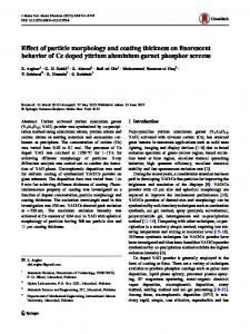
Figure 3a,b show the voltage profiles of the first charge (lithiation) and discharge (delithiation) cycle at 0.1C rate, capacities and Coulombic efficiency during the first cycle, and capacity retention after 50 cycles in the samples with different coating thicknesses as summarized in Table 1. The capacity and Coulombic efficiency decrease with increasing coating thickness during the first cycle. The sample without SiOx -showed charge and discharge capacities of 2895 and 2575 mA h g−1 respectively, which correspond to 88% Coulombic efficiency. The efficiency of the SiOx-free sample is slightly Figure 1. SEM images of: a) etched Si, and b) cross-sectional image of (a) obtained from a lower than those of samples with about 7 focused-ion-beam (FIB) process before carbon coating. and 10 nm-thick coatings, which indicates that the oxide-free Si anode suffered from and about 10 nm, respectively (for TEM images of carbonenhanced side reactions with the electrolyte.[39] After 50 cycles, coated samples with ca. 7 nm-thick SiO2 coating, see Figure S1 the sample with a 7 nm-thick coating demonstrates the best in the Supporting Information). The loading level of the anode performance, showing 2117 mA h g−1 and 84% for first dissamples was about 2 mg cm−2 (active material only) and the charge capacity and capacity retention, respectively. After the electrode thickness of the samples with a 2 nm coating thickinitial cycles, the oxide-free sample had a Coulombic efficiency ness was 29 μm, and with 7 and 15 nm coating thickness were of 99.7%, while the sample with the 2 nm-thick SiO2 coating 24 μm, except for the Cu current collector. exhibited a Coulombic efficiency of 98% (Supporting Information, Figure S2). This result shows that the native SiOx coating layer is not effective to reduce the volume change of the anode sample, and a new solid electrolyte interface (SEI) layer is generated. On the other hand, it has been reported that Si NWs with about 7 nm coating thickness showed a first discharge capacity of around 2000 mA h g−1 with a Coulombic efficiency of ca. 30%.[39] Si@SiO2@carbon nanocomposites with about 10 nm-thick coatings exhibited a first charge capacity of