wireless network is to find a MAC protocol that can support the constraint of ... Finally, hybrid protocols combine the advantages of contention and reservation of ...
IJCSI International Journal of Computer Science Issues, Vol. 8, Issue 3, No. 2, May 2011 ISSN (Online): 1694-0814 www.IJCSI.org
602
Cross-Layer Design For Energy-Efficient In Wireless Underwater Communication: Acoustic Frequency IDentification Case Study
Ghada ZAIBI1, Nejah NASRI1, Abdennaceur KACHOURI1, Laurent ANDRIEUX2 and Mounir SAMET1 1
2
National Engineering School of Sfax (ENIS), University of Sfax, Laboratory of Electronics and Information Technologies (LETI), Tunisia
IUT Blagnac, University of Toulouse Mirail II, Laboratory of Technology and Engineering Systems of Toulouse (LATTIS), France
Abstract Thanks to the recent developments on communication techniques, micro-technology and on digital electronics, Underwater Wireless Sensor Networks (UWSNs) are being employed in several types of underwater applications such as wireless identification named Acoustic Frequency Identification (AFID)[1][2]. In this research, we are trying to adapt concepts of wireless acoustic identification to the difficult underwater environment with its hard constraints especially absence of high bandwidth communication (no radio).So, there is a critical parameter in UWSN making challenge because it determines how longer sensor nodes and the entire networks would remain functional. However, in these types of Networks, node’s battery presents a limited energy resource and network lifetime is related to the energy consumption by a node. Thus, in this paper we will propose some contributions and cross-layer design to prolong the AFID network lifetime. Keywords: UWSNs, AFID, network lifetime, energy consumption, cross layer.
1. Introduction Acoustic Frequency IDentification sensor networks are formed by a large number of sensor nodes distributed over an ocean geographical area named AFID sensor; they are designed to communicate with different underwater objects (Marine vessels, Submarines, some types of fish, etc.) and to communicate with the reader through acoustic links [1][2][3]. These networks could be rapidly deployed and need a very short period to be established and then to reach data
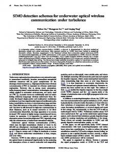
gathering stage. Also, successful underwater navigation is not only crucial for any type of mission, it is also an interesting application for multi-vehicle scenarios as each vehicle has the possibility to improve the knowledge about its own position by exchanging information with AFID sensors fixed in the bottom of see(figure 1)[4].
Fig. 1 Typical architecture of AFID sensors [4]
Unlike traditional wireless networks, UWSN are built to be deployed as an autonomous network without any type of network administration to control data transmission in the common acoustic link. Gathered information, by AFID sensor nodes, are routed through the network to AFID reader having more powerful units in terms of, energy, acoustic unit range and computational operations. Sink’s job is to collect data from AFID sensor nodes and then transmit them to the user, and also can serve as gateway for interconnection to other networks like UWSN. (Figure1). Underwater Wireless Sensor Networks (UWSNs) research has predominantly assumed the use of a portable and limited energy source, viz. batteries, to power sensors [5]. Without energy, an acoustic sensor is essentially useless
IJCSI International Journal of Computer Science Issues, Vol. 8, Issue 3, No. 2, May 2011 ISSN (Online): 1694-0814 www.IJCSI.org
and cannot contribute to the utility of the network as a whole. Consequently, substantial research efforts have been spent on designing energy-efficient networking techniques to maximize the lifetime of UWSNs [6]. However, AFID sensors are required to operate for much longer durations (like years or even decades). This paper surveys related research and discusses the challenges of cross layer designing networking for such AFID networks.
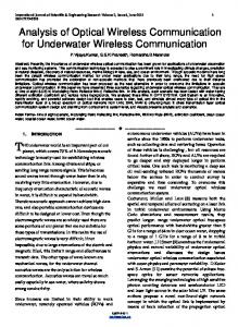
2. Underwater AFID Architecture Underwater AFID node is made up of 3 principal units and a power unit (Figure2) [7]: -Acoustic sensing unit: consists of hardware devices responsible for detection of signal from underwater reader and transmitting data from transponder to the reader. In this sensing, an analog to digital converter is required to convert acoustic signals to digital signals comprehensible by the processing unit. -Processing unit: it consists of a microcontroller unit (MCU) that controls the functionality of other units and components and it is responsible for data processing. Data are temporary stored in an integrated memory (RAM). -Communication unit: underwater nodes use acoustic wave. This unit is the first responsible unit for energy consumption. -Power supply: it is a battery in general and it has a limited energy resource. The battery is responsible for energy supply for all units of the underwater node but it may be very difficult and sometimes impossible to change or to recharge it; for this reason, it’s very important to have strategies for energy conservation. Power Generator
Battery
DC-DC
Processing unit
MCU
Communication unit
ADC
Sensors
Memory Power Supply Subsystem
Acoustic link
Fig. 2 Typical underwater transponder architecture
To perform some specific applications transponders nodes could be equipped with read write memory or a power generator. These additional units make the node bigger and more expensive. AFID sensor networks can be more and more deployed in a wide variety of underwater applications for gathering information in order to develop wireless underwater identification and control. These AFID networks with
603
intelligent autonomous sensors are also powerful in military, surveillance and security applications as underwater detection and tracking systems [8]. AFID sensors can be used for ocean surveillance and underwater security. So, this can be applicable around ships or in entrances of ports. Also, AFID sensor which act as beacons are fitted to aircraft to allow their location in the event of a crash in the sea. To improve the quality of our lives, researches are concentrating in developing AFID networks for many underwater applications and to achieve the full potential of these networks there are a lot of challenges and problems to be confronted.
3. Problems Statement For AFID Network Establishment 3.1 Challenges for establishing an AFID Network Underwater wireless communication is characterized by high level of noise. So, Man-made and natural noises, animal or environmental (waves, rain), can interfere with good acoustic signal. To resume, this section describes the main problems for the establishment of AFID network. - Physical constraints [9][10]: • The bandwidth of acoustic communications is relatively low (0 400 KHz). • Low throughput (less than 50 kbps) • Absorption phenomenon is the fundamental limitation of maximal frequency • limited, range-dependent bandwidth • time-varying multipath • low speed of sound (1500 m/s) • Long propagation delay • noise problems - Energy consumption[10][11]: Waste of energy is the critical parameter for UWSN because of its limited resources in which we cannot profit from energy solar to recharge battery. Energy efficient communication is a key requirement of energy-constrained underwater sensor networks (UWSNs). In this paper, we present a solution which is conventionally used to improve reliability in AFID networks, it can be employed to reduce energy consumption and preserve a reasonable level of data reliability.
3.2 Waste of energy factors Although energy is necessary for unit’s function’s and it is needed for reception or transmission of acoustic signal or energy required for microcontroller to store data there are also other sources of energy waste in UWSN.
IJCSI International Journal of Computer Science Issues, Vol. 8, Issue 3, No. 2, May 2011 ISSN (Online): 1694-0814 www.IJCSI.org
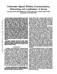
In physical layer waste of energy is due to the bad choice of physical parameters such as optimal frequency [12][13]. So, as it is shown in figure 3, saving energy is based on the finding of optimal frequency for underwater communication.
604
4. Contributions For Saving Energy In AFID Networks Underwater Network lifetime is the important criteria when evaluating AFID Network and as we know it depends on the energy consumption of the node unit’s. This is related to minimize and optimize energy dissipation in every node of the network. Our approach is based on the cross-layering design in which MAC and physical layers should be investigated together. Figure 4 shows the major levels of energy saving for UWSN [4]. Energy conservation levels
Fig. 3 Transmission losses versus frequency
This curve confirms that the transmission losses increase with frequency and distance between readers and transponders. Also, in UWSNs, one of the main factors which cause low event reliability and energy consumption is the techniques of access to the medium [14][15]. So, current UWSNs protocol designs are largely based on a MAC layer approach. Thus, MAC issues are designed and operated independently. We will focus on energy aware MAC (Media Access Control) layer protocols for wireless underwater networks. The most important sources of energy consumption in the MAC layer are [15][16][17]: - Idle listening: a node does not know exactly when it will receive information from other nodes; it should be ready for reception by listening to the underwater channel. Lost information has to be retransmitted. - Overhearing: when a sensor node is listening to the radio channel it can receive parquets that does not belong to it. Energy is wasted for reception and processing. - Overmitting: when a node transmit a message to another node that it is not ready for reception this message will be lost. - Collisions: they are the first cause of waste of energy and happened when two nodes transmit at the same time. In fact, the retransmission of data demands energy. - Overhead: we don’t transmit only user’s data in the radio link but also many kinds of data necessary for the control of communication and for network management. These overhead must be relatively shorter than user’s data to not affect the throughput.
Hardware level -Battery -Processors -Converters -Filters
Software level
-Operating system
OSI model
Higher layers
- Security data - Aggregation data - Compression data Network layer -
- Handling of routing tables Data Link layer
- Using of sleep/active period - Resolve collisions - Minimizing retransmissions -Detection and correction of errors Physical layer
- Choice of modulation types - Types of wave and amplification Fig. 4 Level of Optimization energy [4]
As illustrated in figure 4, there are many levels to reduce energy consumption. However, in hardware and software levels, energy consumption is very limited and continued to decrease with the progress of microelectronics. For this reason, a careful design of all layers of OSI model is required. For underwater wireless communication systems energy consumption is linked to the characteristics of communication media. Several studies have been developed in this field in order to reduce energy consumption. They showed that the physical layer and MAC layer represent the relevant sources of energy consumption. In the physical layer we must make a critical choice of module. So, the energy consumption in underwater
IJCSI International Journal of Computer Science Issues, Vol. 8, Issue 3, No. 2, May 2011 ISSN (Online): 1694-0814 www.IJCSI.org
acoustic networks is due especially to the bad choice of signal frequency. In the MAC layer saving energy essentially amounts to the choice of access methods to minimize the numbers of retransmissions. In this work, cross-layer optimization strategies consist on determining the optimal way to combine the most promising solution in physical and MAC layer to obtain the most efficient network solution.
4.1 Physical layer solution In this subsection, we discuss the relationship between transmission distance and bandwidth. Also, we introduce the frequency allocation methodology that we will optimize energy consumption. The underwater attenuation level is given by the expression [18]: A(r, f) 20 log(r) a(f) r (1) With r is the distance between emitter and receiver, f is the central frequency and a(f) is the absorption coefficient proposed by Wong[18]: 7,858 .10 2 1,481 .10 4 (2) a f f 2 2,692 .10 13 2 2 10 6 f
1,226 .10
f
1,522 .10
From these equations we note that the attenuation is directly proportional to the distance between the transmitter and receiver. Also, we note that attenuation varies with frequency. As a result of simulation figure 5 present the gain of signal for different distances versus frequency. From these curves, the effective bandwidth is generally estimated as the width of the receiver's channel pass band between the 3dB points above and below its center frequency of operation. Gain(dB) 0 -50 -100 -150
Gain(dB)
-200 -250 -300
r=10Km r=5Km r=1Km r=0.1Km
-350 -400 -450 -500 3 10
4
10 Frequency (Hz) fréquence(Hz)
5
10
Fig. 5 Gain (dB) for different ranges depending on the frequency
Table 1 summarizes the bandwidth (-3dB) in the wireless transmission for various underwater range.
605 TABLE 1: BANDWIDTH DEPENDING ON RANGES
ranges(Km) 5 à 10 1à5
Bandwidth (KHz) 5 à 10 10 -25
Attenuation (dB)