To enhance the throughput performance of such networks, it is of prime interest to adapt ... A high data rate transmissi
Cross-layer multi-rate routing strategies in wireless multi-hop random access networks Ju-Lan Hsu and Izhak Rubin Electrical Engineering Department University of California, Los Angeles (UCLA) {jlhsu, rubin}@ee.ucla.edu Abstract—In this paper, we develop and study combined multirate and packet forwarding and routing operations in the context of multi-hop ad hoc wireless networks. Nodes are assumed to employ a software controlled radio that is programmed to use several modulation/coding schemes (MCSs) that operate at different data rates. The underlying MAC scheme is assumed to be based on a random access (pure ALOHA type) protocol. We propose a distributed QoS-aware cross-layer joint routing and rate control algorithm. It is used by nodal stations to jointly select, for each packet that traverses multi-hop routes across the network, the transmit data rate and the neighboring node to which the packet should be routed towards its destination. Each station monitors certain station and network activity states, and uses these data to adapt the selection of its parameter vectors. The mechanism strives to ensure that flow throughput and endto-end packet delay target levels are met. Once satisfied, the algorithm selects parameters that serve to enhance the transport throughput level, thus occupying limited overall network wide resources. Simulation results demonstrate the significant performance enhancements that are achieved under the use of the proposed scheme. Our analytical models and mechanisms provide important guidelines for the design of such joint channel rate, MAC and routing based operations algorithms.
I. INTRODUCTION Multi-hop wireless ad hoc networks have been widely studied over the past few years. To enhance the throughput performance of such networks, it is of prime interest to adapt the parameters of the advanced physical layer technologies enabling higher transmission data rates. While multi-rate operations have been commonly considered in the context of a cross layer MAC control problem, its cross layer impact on network layer operations is largely unexplored. In this paper, we investigate such joint routing and modulation-coding scheme (MCS) adaptation operations under the use of a random access medium access control (MAC) protocol. Consider a multi-rate capable operation in a multi-hop network system. A high data rate transmission may require a higher level of acceptable SINR (Signal to Interference and Noise Ratio) at the intended receiving node. This may lead to reduction in the network’s realized average spatial reuse factor (SRF) and/or the use of shorter link layer communication ranges. From network layer point of view, a flow may then have to be transported along a route that contains a larger This work was supported by the National Science Foundation (NSF) under Grant No. ANI0087148, by University of California/Nokia MICRO Grant No. 05-054, by UC Discovery/BoozAllen_Hamilton Grant No Com06-10214, and by TMS Program No. TMS-094-1-A-02.
number of hops. This produces higher internal traffic loads, which leads to network congestion. Thus, by increasing the nodal transmit rate (and thus shorter communication range), one is not necessarily attaining an overall upgraded end-to-end throughput performance behavior. Under a homogeneous nodal operational setup, we have used the network’s transport throughput level as the key performance metric for calculating the desired (rate and forwarding range) parameter vector. We carry out mathematical analysis to compute the latter measure in terms of the parameters to be determined. We note that the optimal hop range value that serves to yield a maximum value for the realized transport throughput must be parameterized by both the transmission data rate and the network carried load level. In this paper, our main objective is to introduce and characterize a distributed algorithm and protocol for such cross-layer operation when realistic heterogeneous station characteristics prevail. In section III, we provide the mathematical characterizations of such cross-layer interactions under a homogenous nodal setup. In section IV, we employ the mathematical tools developed in III and propose a distributed QoS aware cross layer joint routing and rate control algorithm. It is used at each station to control the selection of its transmit rate and the neighbor to which a packet should be forwarded. The mechanism strives to ensure that the targeted QoS levels are met for the underlying packet, while at the same time the selected parameters aid in enhancing the realized transport throughput performance. Performance results are presented in Section V. Section VI concludes this paper. II. RELATED WORKS The transport capacity of a wireless network with n nodes is noted in [1] to be of order O(n1/2) bit-meters per second. In [2], routing strategies that employ hops of different length have been studied. It is shown that routing over fewer but longer hops may yield better energy efficiency than that attained under nearest-neighbor routing. However, the associated impact of channel interference and medium access effects have not been modeled and accounted for. In [3], the expected maximum density of ‘progress’ under a slotted Aloha MAC has been evaluated. These studies have not addressed the impact of using a multitude of modulation/coding schemes. The work in [4] has investigated the optimum physical carrier
609 1930-529X/07/$25.00 © 2007 IEEE This full text paper was peer reviewed at the direction of IEEE Communications Society subject matter experts for publication in the IEEE GLOBECOM 2007 proceedings.
sensing range that maximizes the throughput performance, by taking into account multi-hop forwarding and the variable transmission ranges realized under he use of different transmit data rates. In [4]-[6], performance tradeoffs involving the system’s spatial reuse factor and the message capture probability are noted. In [9], linear programming techniques are used to solve a joint routing and link scheduling optimization problem to find a path with the largest path capacity in multi-rate multi-hop networks. In [7], it is indicated that the hop distance range and the employed MCS should be jointly selected to yield the highest throughput capacity level for a multi-rate capable multi-hop network system. The work in [8] further characterizes the ensuing transport throughput performance attained by the underlying multi-rate multi-hop wireless network system. To date, few published works have modeled the PHY-MAC-routing performance tradeoffs involved, neither designed modelingbased cross layer algorithms that jointly selects the MCS and next hop station. III. SYSTEM CONSIDERATION AND HOMOGENOUS NETWORK THROUGHPUT PERFOMRANCE CHARACTERIZATION
Nodes in a wireless ad hoc network form communication links with their direct neighbors, when feasible, for the purpose of routing their packets to their corresponding destinations in a multi-hop fashion. Half-duplex radios and a SINR interference model are employed. To characterize a homogenous multi-hop network system when loaded by a wide variety of spatially distributed flows, having a multitude of source-destination pairs, we assume that a station selects the intended receiver for a transmitted packet at random from among its link layer neighbors, and every station always has a nonempty transmission queue. We consider a system that employs a pure Aloha scheme as its link layer MAC protocol. Upon completion of a transmission, an idle station resumes transmission after an exponential idle period with an average duration of 1/λ sec. Packets are of constant length, each containing a b-bit data unit. The transmission time of a packet lasts for T seconds. The latter is a function of data rate rc. A. Link Throughput Performance Analysis To capture the involved parameters’ joint effects on the network system’s performance under a homogenous nodal operational setup, we let a set of parameter values (transmission rate rc and forwarding range y) to be universally used by every nodal station throughout the network system. From [8], the probability of successful transmission from a node 0 to a node Y (with forwarding range y) at rate rc is denoted as Ps|y and is given by: (3-1) Ps| y = Pidle (Y ) ⋅ Pr{SINR at node Y ≥ γ } . where γ is the required SINR threshold at rate rc and Pidle(Y) is the probability that node Y is idle during the packet transmission that takes place in [τ, τ + T(rc)). For analytical derivations, nodes are assumed to be spatially distributed in accordance with Poisson process over a plane of infinite scope, at spatial intensity υ over the plane R2. Assume
additionally a power law path loss model, with α denoting the attenuation factor, α>2. We omit the detailed derivations and only present here the resulting expression for Ps|y: ([8]) 1 Ps| y = e−λT ⋅ . (3-2) 1 + λT 1 − λT −α + −2 / α e )(( y / γ − N / P ) ) ] exp[−πυ (1 − 1 + λT where [x]+ = max (0, x), and the nodal transmission power and noise power are denoted by P and N respectively. The overall network load intensity G and link layer throughput intensity conditioned on link distance y, S|y are, respectively, given by G = b ⋅ Pr{idle} ⋅ { packet generation intensity | idle} = b⋅
bits sec⋅ m 2 bits . sec⋅ m 2
1 ⋅ λυ 1 + λT
S| y = G ⋅ Ps| y
.
(3-3)
(3-4)
B. Transport throughput performance in multi-hop wireless networks The sum of the product of flow throughput values and the distances over which those flow bits are carried, aggregated over all flows, and expressed per unit area, is defined as the network’s transport throughput intensity. Assuming an operation under which the average path distance level is determined by the underlying nature of the spatial distribution of user flows, we proceed to use the transport throughput intensity as a metric for characterizing the multi-hop network’s performance behavior. Consider a scenario where forwarding nodes are optimally placed or the nodal spatial intensity υ is high enough so that nodes have no problem in finding forwarding nodes at desired locations. The achieved transport throughput intensity (conditioned on forwarding range y) is expressed as: 1 e − λT ) ⋅ . (3-5) + 1 λT / γ − N / P )−2 / α ] ⋅ y ⋅ cos(arg(Y ))
St | y = υ bλ (1 + λT )−2 e − λT ⋅ exp[−πυ (1 − ( y −α
where |Y|cos(arg(Y)) denotes the ‘effective’ distance traversed in the direction of the final destination in one hop, often identified in the literature as ‘progress’. If we take derivative of the throughput rate function given by Eq. (3-5) (let N = 0, noting such an approximation is reasonable in interference limited networks) with respect to y, we derive the optimum hop distance y* that maximizes the expected attainable transport throughput level St|y*: 1 y* = 2πυ (1 − e − λT ) 1 + λT
−1/ 2
γ −1/ α .
1 St | y * = b 2πυ (1 − e − λT ) 1 + λT
−1 / 2
(3-6)
γ −1 / α (1 + λT ) −1 e − λT −1 / 2 . (3-7)
IV. DISTRIBUTED QOS-DRIVEN CROSS-LAYER ROUTING AND RATE CONTROL ALGORITHM
In the previous section, we investigated the impact of various parameters in a homogeneous system by assuming all users in the network system to employ the same parameter set. Such configuration, however, rarely reflects a realistic network
610 1930-529X/07/$25.00 © 2007 IEEE This full text paper was peer reviewed at the direction of IEEE Communications Society subject matter experts for publication in the IEEE GLOBECOM 2007 proceedings.
operation scenario and hardly utilizes the resource in the most efficient way. In this section, we aim to devise a distributed mechanism that is used by each relaying station to perform joint rate and routing adaptations in the multi-hop random access network system, on a packet-by-packet base. Consider a network carrying multiple connectionless datagram type end-to-end data packet flows. Furthermore, packets may desire a certain QoS objective; thus, each packet is subjected to targeted (flow based) end-to-end throughput and delay performance requirements. For each packet arriving at a node, the node proceeds with the joint selection of the next hop node j and the channel rate rc to be employed in forwarding the packet. In doing so, the node considers only such joint parameter vectors v = (rc, j) whose values permit the packet to meet its targeted throughput and packet delay performance levels. For this selection, we aim to choose the vector v∈ V that maximizes the expected transport throughput of the packet, where V denotes the set of acceptable parameter vectors (rc, j) that have a chance of assuring the packet with meeting its target end-to-end delay and flow rate values. In this manner, one strives to ensure that the transport of the packet uses only the network transport resources that are required for its (per required QoS) successful transport, freeing other resources for use for other packet transport purposes. A. System design and operations Conventional rate control/adaptation algorithms are often designed as part of the link layer operation. In this paper, we introduce a cross-layer multi-rate driven operation involving the physical, MAC and network layers. By using route selection considerations in selecting the parameter vector, we are able to more effectively utilize network wide resources and to take into account end-to-end packet delay objectives. The following nodal monitoring structure is employed. Each node i maintains sliding windows across which it monitors and summarizes the statistics of its activity, e.g., calculating the probability that its own transmission queue is in busy (nonempty) state, denoted as qi. In the same manner the node also compiles the distribution histogram of its employed packet transmission duration Ti, denoted as {P(Ti = t)}. In addition to the data communications channel, a control channel is employed. The latter is used by each station to broadcast periodically control messages to its (lowest rate) direct neighbors, using the lowest transmit data rate. The station includes in a control message data about its activity statistics, such as qi and {P(Ti = t)}. We note that by transmitting control messages at the lowest rate, a node is able to distribute its state over a wider geographical scope. The set Ni is hence defined to contain all the (lowest data rate) neighbors of node i. We assume that a station is able to acquire data concerning its distance to each of its link level neighbors. For example, stations may use received signal strength (RSS) ranging techniques to measure the distances. Furthermore, when end-to-end delay target levels are incorporated, an estimate of the distance to be traveled by a packet to its destination node is acquired at intermediate nodes. Such an estimate can be based on data provided by the source node, and/or gathered by nodes during a discovery process, or by other means.
B. Per packet throughput performance calculation for QoS support We next consider the data packet transmission and transport process. Suppose that station i has a ready packet. Assume that the packet’s header contains a timestamp that identifies the packet’s generated time at its source node. The packet’s header also specifies the packet’s targeted end-to-end throughput and delay QoS requirements, denoted by TH and D respectively. In order to guarantee this packet with its desired QoS level, station i needs to calculate a set of acceptable parameter vectors V that have a chance of assuring the packet with meeting its end-to-end delay and flow rate target values. In Eq. (4-1), the throughput level S(i,j,rc) attained when node i transmits to neighboring node j at rate rc, is calculated by multiplying the packet length (b bits) by the probability of successful packet transmission, Ps(i,j,rc), and then divided by the average per-station transmission cycle time, yielding 1 S (i, j, rc ) = b Ps (i, j, rc ) T (rc ) + λ
.
(4-1)
According to Eq. (3-2), Ps(i,j,rc) is the product of the probability that node j is idle for the packet transmission duration and the probability that j’s received SINR is higher than a desired threshold γ. We modify the mathematical expressions given in Eqs. (3-2) – (3-3) by using the monitored activity statistics of nodes residing in the impacting neighborhood of sending node i, to obtain the following expression for the probability of successful i-to-j packet transmission (at rate rc): Pidle ( j, rc ) = q j
e − λT ( rc ) + (1 − q j ) . 1 + λ E[T j ]
Ps (i, j , rc ) = Pidle ( j ) ⋅ exp[−π
1 ⋅ ( ∑ ∑ P (Tn = t ) ⋅ π Rmax 2 n∈Ni \{ j } t
(4-2)
1 qn (1 − e − λt )) ⋅ ( dij −α / γ (rc ) − N / P )−2 / α ] 1 + λt Alternatively, rather than having each node advertising in its neighborhood its monitored activity statistics, each node i can directly monitor the channel and continuously measure and update the distribution of its monitored interference power FIj(x) = Pr{Ij ≤ x}. If each node has the latter statistics to be advertised in its neighborhood, the probability of successful packet transmission can then be calculated as: − λT e j Ps (i , j , rc ) = q j + (1 − q j ) ⋅ FIj ( Pd ij −α / γ − N ) . (4-3) 1 + λT j
C. Delay performance calculation for QoS support To estimate the residual end-to-end delay to be experienced by an arriving packet as it travels in the network, a node proceeds to include (in a cumulative manner) in the packet’s header information that identifies the overall delay incurred by the packet here-to-fore (including the delay experienced in its own nodal system), or rather the residual delay budget DB (identifying the time remained for delivering the packet to the destination within its desired end-to-end delay target level). We note that when such residual delay data is not included in the packet’s header, other delay budget estimates can be invoked. For example, based on the packet’s application type (e.g., as identified by an application port identifier or by a
611 1930-529X/07/$25.00 © 2007 IEEE This full text paper was peer reviewed at the direction of IEEE Communications Society subject matter experts for publication in the IEEE GLOBECOM 2007 proceedings.
DSCI in case the packet includes a Differentiated Services tag), a node can check whether the actual delay experienced by the packet during its residence at the node satisfies a per hop delay budget requirement. Upon arrival, the packet’s waiting time in the transmission queue is estimated. It is admitted into station i's queue only if the estimated level is acceptable. Such waiting time estimates may be roughly derived from the experienced waiting time of the head-of-line packet, and/or from the queue size. Note that once admitted, the actual experienced waiting time level is used to calculate the estimated one-hop delay. To do so, a node proceeds first to estimate the head-of-line delay incurred by the packet. The latter expresses the time period elapsed between the instant at which the packet enters the head of the line position in station i's transmission queue and the instant of time at which the packet is successfully received by neighboring station j. The packet queueing and transmission processing at station i is described by a queueing system model, for which the effective packet service time is set equal to the message head-of-line delay. We denote the mean service time, identifying the mean time it takes for successfully transmitting a packet from i to j at transmit rate rc, by B(i,j,rc). Its value is computed by multiplying the station’s mean cycle time by the expected number of transmissions incurred until successful reception takes place. As an approximation, we assume the number of these random access transmission trials to be governed by a geometric distribution with parameter Ps. Hence, B(i,j,rc) is written as: 1 1 . (4-4) B(i,j,rc ) = ( +T(rc )) Ps (i, j , rc ) λ The total mean one-hop delay D(i,j,rc) incurred by a packet transmitted by station i to node j (at rate rc) is equal to the sum of its experienced queueing delay (i.e., waiting time Wi) and mean service time B(i,j,rc): (4-5) D(i,j,rc )=Wi +B(i,j,rc ) . Using Eq. (4-5), station i needs to satisfy the following delay requirement in forwarding the packet: (4-6) D (i, j , rc ) + D r min ( j , di r ) ≤ DB . r where D min is calculated by station i as a lower bound estimate on the residual end-to-end delay of the packet at station j. The residual distance progress to the destination at node i, dri, is used (along with the known range dij) to estimate the residual distance to the destination at node j. This lower bound is derived by assuming all transmissions to the destination (at node j and at subsequent nodes along the route) to be successfully executed upon their first trial, excluding thus queueing delays. Hence, Drmin is computed as the product of the station’s cycle time and the residual hop length, using the data rate that minimizes such overall residual delay value: (d ri − dij ) 1 r (4-7) Dmin ( j, dir ) = min{( +T(rc )) ⋅ } . −α rc ∈Rc λ N P γ (r )/ ( ) c If a station i is unable (or does not wish to allocate resources for such an operation) to predict a residual delay value for a packet, we assume it to set Drmin = 0. In turn, for networks that use regional or global state distributions, such as those that employ link-state type routing mechanisms, a station may be able to compute tighter estimates of the residual packet delay to be experienced by the packet.
D. Per-packet transport throughput maximization To maximize the expected transport throughput of the packet, we include in each node a routine that serves to mathematically calculate the network’s transport throughput level. This computation is based on the formulas presented in Eqs. (3-5) and (4-1). The latter yield a formula for the transport throughput value (St) involved in transporting a packet from station i to node j at data rate rc, (4-8) St (i, j , rc ) = S (i, j, rc ) ⋅ dij cos(δ ij ) . where dijcos(δij) denotes the expresses the distance value of the projection of the one-hop progress (dij) vector across the line connecting the source station towards the final destination. Each node then proceeds, following the procedure described above, to calculate the data rate, forwarding range and next hop receiving node to which a packet is forwarded. In Table 1, we outline the procedures, used to determine at a node, for each received packet, the preferred cross-layer operation. When a selection that satisfies the desired QoS target levels cannot be realized, the underlying packet is dropped. V. PERFORMANCE EVALUATIONS We have used a discrete event based C++ simulator to evaluate the throughput performance of the proposed crosslayer joint routing and rate-control algorithm. In the simulations, there are 40 nodes distributed in a 200m x 200m topology. We consider the MCS provided by IEEE 802.11a systems. The transmission data rate levels and the corresponding required SINR levels for successful reception, per MCS, are given in Table 2 for a targeted BER value of 105 ([10]). For the IEEE 802.11a protocol, the PLCP preamble plus SIG duration, denoted as T0, and the data rate dependent overhead length induced by the PHY and MAC structures, denoted as b0, are equal to 20 µs and 246 bits, respectively. Packet length b is assumed to be 1000 bytes. The value of packet transmission time T is given by (5-1) T(rc) = T0 + (b+b0)/ rc . Table 2. Data rate vs. SINR threshold table for target BER = 10-5. Rate (Mbps) 6 9 12 18 24 36 48 54 γ (dB) 6.02 7.78 9.03 10.79 17.04 18.8 24.05 24.56
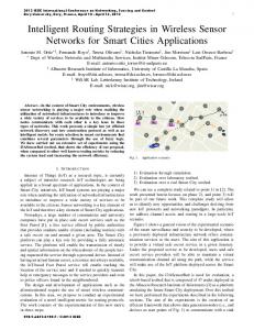
The transmission power is fixed at 1mW; the transmission ranges for the set of MCSs under consideration, are 125.8, 113.6, 105.7, 95.6, 66.7, 60.3, 44.5 and 43.3 meters. The network is loaded by four simultaneous flows. Each source generates flow packets at a rate faster than the underlying medium access rate, such that it has a non-empty transmission queue at all times. We compare the following algorithms, in addition to using the proposed cross-layer scheme defined above: 1) Under the max progress algorithm, a node selects the next hop node for a packet’s transmission from a set that consists of its lowest rate neighbors that provide the highest progress range in the direction of the destination node. It then uses the highest transmit rate that enables it to forward the packet to the selected node. This scheme thus acts as a distributed approximation to the shortest path (lowest hop count) algorithm. 2) Under the max rate algorithm on the other hand, a node strives to select the highest transmit rate that will enable it to forward its packet to a neighboring node. If multiple neighbors can be reached at this rate, the one that
612 1930-529X/07/$25.00 © 2007 IEEE This full text paper was peer reviewed at the direction of IEEE Communications Society subject matter experts for publication in the IEEE GLOBECOM 2007 proceedings.
yields the highest progress range is selected. 3) Under the fixed rate-18 algorithm, the transmit rate is fixed at the 18 Mbps level. In this paper, we present performance results obtained when no targeted QoS levels are imposed. The network’s realized aggregate throughput is used as a performance metric. Performance results are illustrated in Fig. 1. It is observed that the proposed cross layer joint routing and rate-control algorithm outperforms the other algorithms. We especially note the superior throughput performance attained by using the cross layer scheme under highly congested scenarios. The performance gains demonstrated by the cross layer scheme are enabled by the capability of the joint rate-control and forwarding range algorithm to dynamically adapt to underlying monitored network loading and interference conditions. The cross-layer algorithm presented above provides also for a QoS based operation. We thus plan to analyze and evaluate such an operation in a subsequent study. 7
x 10
6
Throughput (bps)
6 5 4
cross layer max progress max rate fixed rate-18Mbps
3 2 1 0 0
Distributed QoS-aware cross-layer routing and rate control algorithm at node i Inputs: 1. State activity measurements yielding estimates of the nodal: a. Probability of nonempty transmission queue, q i ; b. Histogram of packet transmission times Ti : {P(Ti =t)}. 2. Distance estimates d ij between itself and each one of its neighbors j, j ∈ Ni . Control channel operations: 3. Across a control channel, the node periodically broadcasts, at the lowest transmit data rate, its nodal ID and its state activity measurements. 4. Upon receiving new status data across the control channel, the node records the corresponding states of nodes that reside in its neighborhood N i ; Rate and routing selections for data communications: 5. An admitted packet k, with throughput and delay objectives (TH k and Dk ) and residual delay budget DBk , experiences a waiting time Wi in the queue and enters the head-of-line for transmission: 5.0. If i is the source station, do DBk = Dk . 5.1. Do DBk ← DBk − Wi
1000
2000 3000 lambda (1/s)
4000
5000
Figure 1 Throughput performance versus medium access rate λ.
5.2. Set: Vi = {( j , rc )}, ∀j ∈ N i , rc ∈ Rc . 5.3. Check accomodation of the packet's flow throughput objective (TH k ): ∀( j, rc ) ∈ Vi : S(i,j, rc ) < TH k ,do Vi = Vi \ {( j , rc )}
REFERENCES [1]
Table 1. The distributed QoS-aware routing and rate control algorithm.
P. Gupta and P. R. Kumar, “The Capacity of Wireless Networks,” IEEE Trans. on Information Theory, Vol. 46, No. 2, March 2000. [2] Martin Haenggi, 'On Routing in Random Rayleigh Fading Networks,' IEEE Transactions on Wireless Communications, Vol. 4, No. 4, JULY 2005. [3] Baccelli, F., Blaszczyszyn, B., Muhlethaler, P. (2004) An Aloha protocol for multihop mobile ad-hoc wireless networks, in Proc of 16th ITC Specialist Seminar, Antwerp, Belgium, 29-40. [4] H. Zhai and Y. Fang, ''Physical Carrier Sensing and Spatial Reuse in Multirate and Multihop Wireless Ad Hoc Networks,'' in Proc. of The IEEE International Conference on Computer Communications (INFOCOM'06), Barcelona, Spain, April 23-29, 2006. [5] J. Zhu, X. Guo, L. L. Yang, and W. S. Conner, “Leveraging spatial reuse in 802.11 mesh networks with enhanced physical carrier sensing,” in Proceedings of IEEE ICC, June 2004. [6] X. Yang and N. H. Vaidya, “On the physical carrier sense in wireless ad hoc networks,” in Proceedings of IEEE Infocom’05, March 2005. [7] J. Hsu and I. Rubin, ‘Performance Analysis of Multi-rate Capable Random Access MAC Protocols in Wireless Multi-hop Networks,’ in Proc. PIMRC’06, 2006. [8] J. Hsu and I. Rubin, ‘On routing and rate control strategies in wireless multi-hop random access networks,’ to appear in ICC’07, 2007. [9] H. Zhai and Y. Fang, ``Impact of routing metrics on path capacity in multi-rate and multi-hop wireless ad hoc networks,'' the 14th IEEE International Conference on Network Protocols (ICNP'06), November 12-15, 2006. [10] J. Yee and H. Pezeshki-Esfahani, “Understanding Wireless LAN Performance Trade-Offs,” www.commsdesign.com/csdmag/sections /feature_article/showArtcle.jhtml?articleID=16505827
5.4. Check the joint parameters that satisfy the packet's residual delay level : ∀( j, rc ) ∈ Vi : D(i,j,rc ) + D rmin (j,d ri ) > DBk , do Vi = Vi \ {( j , rc )} 5.5. Select the next hop station (node j) and the transmission data rate (rc ): if Vi ≠ ∅, (rc , j)ik = arg max St (i, j, rc ) (j,rc )∈Vi
else, drop packet k and end. 1 5.6. Do DBk ← DBk − (T ( rc ) + )
λ
5.7. Transmit packet k according to the underlying MAC: if successful transmission, move on to the next packet if queue is non-empty; else end. else, go to step 5.6.
613 1930-529X/07/$25.00 © 2007 IEEE This full text paper was peer reviewed at the direction of IEEE Communications Society subject matter experts for publication in the IEEE GLOBECOM 2007 proceedings.