Crossroads - A Time-Sensitive Autonomous Intersection Management Technique Edward Andert, Mohammad Khayatian, Aviral Shrivastava Compiler-Microarchitecture Lab, Arizona State University
[email protected],
[email protected],
[email protected]
ABSTRACT For autonomous vehicles, intelligent autonomous intersection management will be required for safe and efficient operation of the intersection. In order to achieve safe operation despite uncertainty in vehicle’s trajectory, intersection management techniques must consider a safety buffer around the vehicles. For truly safe operation, the safety buffer should also account for the network and computational delay caused by communication with the IM (Intersection Manager) to request entry and receive a reply. However, modeling the worst-case computation and network delay as additional safety buffer degrades the throughput of the intersection. To avoid this problem, AIM[1] - a popular state-ofthe-art IM adopts a query-based approach, in which the IM only provides a yes/no answer to vehicle’s queries of speed and arrival time. Although this solution does not degrade the position uncertainty, but it increases the network traffic, the amount of computation on both the car and the IM, and ultimately results in poor intersection throughput. We present Crossroads - a time-sensitive programming method to program the interface of a vehicle and IM, without requiring additional buffer to account for the effect of network and computational delay, and enables efficient intersection management. Our results on 1/10 scale model of intersection using TRAXXAS RC cars demonstrate that time-sensitive programming based approach Crossroads obviates the need for large buffers to accommodate for the network and computation delay, and can reduce the average wait time for the vehicles at a single-lane intersection by 24%. To compare Crossroads with previous approaches, we perform extensive Matlab simulations, and find that Crossroads achieves on average 1.62X higher throughput than simple VT-IM with extra safety buffers, and 1.36X better than AIM.
1.
INTRODUCTION
As cars become autonomous, intersections are no longer constrained by the humans that are currently driving and instead, automated Intersection Managers (IMs)1 can make intersections safer and more efficient. IM interacts with the vehicles as they approach the intersection to find a safe and efficient way to operate the intersection. There are 2 main ways to design the interface between the vehicles and the IM. The first is the most intuitive one, which we call Veloctiy Transaction IM (or VT-IM) – in which the 1
In this paper we use the acronym IM for both intersection manager and intersection management. The correct word will be clear from the context.
approaching vehicles announce their arrival to the IM, and the IM provides them with a velocity to follow, that will not only ensure safe but also efficient operation of the intersection. To guarantee the safety of vehicles in this and as a matter of fact, any other intersection, a safety buffer must be considered around the vehicle which accounts for the uncertainty in the position and velocity of the vehicle. The uncertainty in the position and speed of the vehicle can be due to various reasons, including the errors in various sensors and actuators, the data fusion algorithms, and even due to the clock synchronization drift between the vehicle and the IM. However, for a truly safe operation in an VT-IM, the safety buffer calculation should also take into account the network and computation delay related to the interaction between the vehicle and the IM. Here the network delay is the variable lag in delivering information to the intersection manager and then back to the vehicle, and computational delay is the time it takes for the IM to compute the correct response to send back to the vehicle. Together network and computation delay compose RTD (Round Trip Delay). Neglecting RTD makes VT-IM scheduling methods vulnerable to uncertainties and may lead to accidents. The safety buffer should correspond to the worst-case RTD. To test the effects of error and worst-case RTD, we implement a 1/10 scale intersection model using 8 Traxxas RC cars setup for autonomous driving with a top speed of 3.0 m/s and a length and width of 568mm by 298mm respectively. The cars communicate with the IM using a NRF24L01+, 2.4GHz serial network adapters. For our car intersection setup, the worst case safety buffer due to the control and clock error was about 78mm, while the buffer due to the RTD was about 450mm. Clearly the buffer due to RTD is quite significant! In real cars, we expect the safety buffer due to sensor and actuator error to be smaller, since they use higher quality components, but the safety buffer due to RTD can be much larger due to longer communication distance of the vehicle with the IM, and much higher traffic at intersections. Adding such large safety buffers, although necessary, severely degrades the performance of the intersections. One way to avoid having this large safety buffer due to RTD is to use a Query-Based IM (QB-IM) design. This approach is quite popular, and is used in AIM project[1, 2]. In this, the vehicle approaches the intersection at a constant speed, and sends a speed query to the IM, and IM only replies with a yes/no answer. If the answer is yes, the vehicle can continue moving with the speed, and if the answer is no, the car slows down to a lower speed, and makes a request
Figure 1: Five vehicles in a real implementation. Top speed 3.0 m/s. Intersection lines are overlayed after the test. again. Although QB-IM approach does not incur error in the position of the vehicle due to RTD, and therefore extra safety buffer is not required, however, in such an IM design there is not much scope for the IM to optimize the traffic at the intersection. In particular, the QB-IM design cannot solve an optimization problem and send it’s result to the vehicles – it can only give a yes/no answer and achieve safety. Ultimately, a QB-IM will increase the network traffic, the amount of computation on both the car and the IM – all finally result in poor intersection throughput. To solve this RTD related extra safety buffer problem correctly, we present our approach: Crossroads - a timesensitive programming method to program the TT-IM, without requiring the additional buffer due to RTD. Crossroads solves the extra safety buffer problem by fixing the action time of the new speed received by the vehicle, so that the position of the vehicle becomes deterministic. We use 1/10 scale models and design several traffic scenarios to test the two IM techniques, the vT-IM, which requires extra safety buffers, and Crossroads (that does not require the extra safety buffers). We find that in Crossroad, the average and worst case slow downs of the car 16% less 24% respectively. We also implemented all the three IMs (the simple VT-Im, Crossroads, and AIM) in Matlab to study the scalability of our approach. We run the intersection for randomly generated cars for different input flow rates. We find that at low input rates, all the techniques perform almost the same, however, as input rate increases, the throughput of VT-IM drops sharply. QB-IM works better, but Crossroads scales very well. On average over all input flows, Crossroads of cars per second ) than has 1.62X better throughput ( number average delay per car VTI-IM, and 1.36X better than AIM. The performance overhead and network traffic of Crossroads and VT-IM is up to 20X lower than AIM due to it’s query-based approach.
2.
between intersection and designated transmission line is 3m. The maximum velocity of the cars is limited to 3m/s. We used RWD (rear wheel drive) Traxxas Slash RC as the chassis. The stock motors were exchanged with smaller motors with built in quadrature encoders for fine-grain feedback control. Arduino Mega 2560s were used as the central control unit of the vehicles. Arduino Nanos were utilized to monitor quadrature encoders for localization of the vehicles. Bosch BNO055 9DOF sensor fusion IMUs were used for steering feedback. For wireless communication, NRF24L01+, 2.4GHz serial network adapters were utilized. Our setup is similar to [3]. The vehicle interaction with the IM is implemented broadly as a state machine with 4 states: i) Arriving state: The vehicle is in this state before it reaches the transmission line. ii) Sync state: Once the vehicle reaches the transmission line, it registers with the IM, and sends a sync request to the IM. The IM sends back the time synchronization data (Based on NTP) [4]. iii) Request state: Once the time sync is achieved, the vehicle transmits a packet of data to the intersection manager requesting to make an intersection crossing. After processing the requests ahead in a FIFO queue, the IM computes the response for the vehicle and sends the response (e.g., proceed at a particular speed). vi) Follow state: Once the vehicle receives the plan from IM, the vehicle then follows the plan, and when it crosses the intersection, the vehicle sends an exit timestamp to notify the IM, and goes back to the Arriving state for the next intersection. The exit timestamp allows us to track wait time of each vehicle. Different IMs are implemented and run on a laptop with 10 GB memory, Core i7 -3517u @1.9/2.4 GHz CPU and Windows 8.1 64-bit OS. The IMs are written in Matlab R2016. The communication between the vehicles and the IM is an exchange of about 44-bytes of data for each vehicle. In some rare cases, when a re-transmit is needed because of communication timeout, resulting, there is an overhead of 24 bytes per re-transmit.
3.
SAFETY BUFFER CALCULATION
In any real system (not simulation), there are always uncertainties/inaccuracies in identifying the exact state of the system – in our case, the position and velocity of the vehicles. The uncertainty in the state of the system can be due to several reasons, including the sensor errors (in our case, the position and speed sensors), the errors due to state estimation algorithm used (for example, if a GPS and IMU are used to estimate the position and the velocity of the vehicle, then the sensor fusion algorithm can affect the accuracy of the position and velocity), and even due to the difference in the clocks of the different components of the system (in our case, the synchronization error between the IM and the ve-
SETUP TO EVALUATE IM
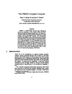
Most Intersection Management (IM) techniques have been evaluated on simulators, therefore researchers did not encounter timing and error related problems. In order to test the effectiveness of IM policies on a physical intersection, we created a 1/10 scale model. As shown in figure 1, we have designed a 4-way intersection with one lane per road. The size of the intersection is 1.2 × 1.2m2 and the vehicle length and width are 0.568m and 0.296m respectively. Each car will start communicating with the intersection manager when crossing a designated transmission line. The distance
𝑬𝑳𝒐𝒏𝒈
𝑳
𝑬𝑳𝒐𝒏𝒈
𝑬𝑳𝒂𝒕
𝑾 𝑬𝑳𝒂𝒕
Figure 2: Vehicle modeled with lateral, longitudinal error including round-trip delay.
chronization error is 3mm. Overall in our system a safety buffer of size 78mm is needed to be added to tthe front and back of the vehicle to account for the inaccuracy in the position. The lateral error (along the width of the lane) can be disregarded because it is less than the lane width and therefore does not affect any calculations. Figure 3: Expected velocity versus actual velocity due to control algorithm errors, and sensor errors. hicle). In order to achieve safe operation of the intersection, a safety buffer must be modeled around the vehicles. The safety buffer essentially implies that the vehicle can be anywhere within the buffer and the movement of the vehicles must be planned/implemented such that the safety buffers do not overlap at any moment in time. Next we show how we estimate this safety buffer for our vehicles.
3.1
Estimating Sensing Error
Vehicle positioning is based on acquired measurements from sensors, so an IM design must take into account the error propagated from GPS, encoder, etc. It should be noted that an encoder error would affect the vehicle longitudinally, whereas GPS error would affect a vehicle both laterally and longitudinally. Figure 2 depicts both cases. Although it may be possible to estimate the size of safety buffer around the vehicles using the error numbers from the data sheets of the sensors, it is still hard to estimate the affect of the data fusion and control algorithms on the buffer. Therefore, we devise an experiment to estimate the error in the overall position and velocity of the car, and use that to estimate the buffer size. As shown in figure 3, we start the experiment with the vehicle at position P0 , with velocity v0 , at start time T0 . The vehicle then attempts to hold velocity v0 until it reaches time T1 . At T1 , the vehicle accelerates until it reaches velocity v1 at time T2 . The vehicle then maintains the velocity v1 until time T3 . Suppose that ideally the vehicle should have reached position P3 at time T3 , then the error in the final position will be Elong = P3 − Pactual . The worst-case positive control error will happen in our model when v0 = 0.1m/s and v1 = 3.0m/s. And the worst case negative error will happen when v0 = 3m/s and v1 = 0.1m/s. Using the worst case of these 2 test, we can determine the outer bound of our longitudinal error Elong , which will consequently become the Safety Buffer. We perform this experiment 20 times, and measure Elong . The maximum value of Elong was 50ms. Therefore at maximum speed, the buffer due to vehicle control error is 75mm.
3.2
Estimating Time Synchronization Error
Our physical implementation is a distributed system containing multiple nodes communicating with the central server. Without proper synchronization, commands given to nodes can be executed at different time, depending on when the command is received. Synchronization is the solution to have the same understanding of time among the nodes. Different time synchronization methods like NTP, PTP, GNSS, etc. can be used in order to synchronize with the server. We utilize NTP (network Time Protocol) for synchronization in our setup. Our time synchronization error with NTP is well defined and is 1 millisecond over the course of the test. Therefore, at maximum speed, the buffer due to time syn-
4.
TIMING PROBLEMS IN VT-IM
Velocity Transaction IMs or VT-IMs work in a manner in which, when a vehicle makes an entrance request, the intersection manager calculates the optimal speed and sends it back to vehicle. Then, the vehicle executes the received command. The algorithms 5, and 4 show how the IM and vehicles collaborate with each other. Algorithm 1: Scheduling Algorithm - Vehicle 1 2 3 4 5
if transmission line is crossed then send a request to IM; receive a response from IM; execute the command; end Algorithm 2: Scheduling Algorithm - IM
1 2 3 4
if a request is received then V = calculate(); send(V); end
Although VT-IMs provide the high throughput by adopting FCFS or other scheduling algorithm, it does not consider computational delay caused by intersection manager and network delay imposed due to communication. Neglecting these delays affects the system correctness because the vehicle executes the received velocity command as soon as it is received. Figure 4 depicts how round trip delay (RTD) affects the position of the car. In order to achieve safe operation, we must add extra safety buffer around the vehicle to take into account the worst case RTD. The RTD or Round trip delay consists of computation delay, and the communication delay. Computational delay is the amount of time it takes for the intersection manager to compute the required information a vehicle needs. Compute time is longest when the most cars requests are in the queue, therefore the worst case can be defined as four car arrivals at the exact time, one in each of the 4 directions. The resulting worst-case RTD from 10 tests with four car arrivals was 135 milliseconds. The network delay is the time requires to send the information back and forth between the car and the IM, assuming the computation on IM is instant. In order to measure this delay, each request message can be followed by an acknowledge message from the receiver. Subtracting the
Figure 4: Round-Trip delay and computational delay cause late command delivery
time the message is sent, from the time the Ack is received, network delay for that message is accounted for. For our 2.4 GHz wireless devices, the network delay was quite nominal, and came to be 15 milliseconds. So, we have bounded RTD with 150 milliseconds. At maximum speed, the 150 ms delay would equate to an extra 0.45m length being added to the front and back of the vehicle. With the worst-case RTD bound and Safety Buffer added in, our vehicles will be 3.46x longer longitudinally than they were originally. In order to guarantee the safety of the vehicle, the WorstCase Computational Delay (WCCD) should be considered based on the worst case scenario.
garding existing vehicles. If the request gets rejected, the vehicle prepares to stop before the intersection line. Algorithm 3: Query Algorithm - IM 1 2 3 4
Algorithm 4: Query Algorithm - Vehicle 1 2
5.
RELATED WORKS
3 4
5.1
Velocity Transaction Based IMs
Capitalizing on the optimization problem that intersection scheduling presents, there have been a number of works looking at the problem of how to schedule vehicles most efficiently using a velocity/acceleration profile based control methodology. In 2012, Lee and Park introduced a optimal methodology in order to scheduling the incoming vehicles [5]. They constructed a conflict look-up table for vehicle entrance and exit lanes. The work is limited to simulation. Similarly, Zohdy, et al. solved an optimization problem to minimize the total delay. They proposed a tool which avoids collision based on characteristic of vehicles [6]. Unfortunately, neither of these methods consider the WCRTD problem and its effect on the safety of their policies. In 2016, Tache et. al. proposed a batch scheduling technique that features a re-organization period where any vehicles that have reached the transmission line in a certain period of time can be shuffled around to find the most efficient order of entrance to the intersection [7]. After the reshuffling period has elapsed for a given vehicle, the intersection manager picks the vehicle velocity using a scheduling technique where the vehicle entrance time is set as the time the last vehicle occupying the designated lane has exited. The authors claim that the throughput can be doubled in comparison with fair scheduling. The authors implemented the technique for a two lane case in simulation. Computation time and network traffic overhead would be very high method because of the reordering, thereby increasing WCRTD. Because the authors do not model RTD, the work could not be applied to a physical system. Some TT-IM methods implemented in a physical model, but at speeds too slow to experience timing and modeling issues. In [8], a fuzzy controller for a simple crossroad is presented. They evaluated their work by experiment on 2 mass produced vehicle in Spain. Perronnet et all implemented a simple 2 way intersection utilizing Lego NXT robots and road marking to test intersection management protocols on a realistic model [9].
5.2
if a request is received then V = calculate(); send(V); end
5 6 7 8 9 10
if designated line is crossed then send a request; receive a response; if Approved then keep driving; else slow down and prepare to stop; request again after the Timeout; end end
AIM has a number of problems including a high computation load due to processing multiple requests and performing a simulation for each request. AIM has extra communication overhead because when a request gets rejected, the vehicle have to make a new request. In addition, AIM cannot achieve the maximum throughput since it simulates the trajectory for only two speeds (current and max), and this query based management limits the IM from reach maximum efficiency. Dresner and Stone implemented an augmented reality simulation using their Java based Autonomous Intersection Simulator, where virtual cars shared a 4 way stop intersection with an actual autonomous car for the 2007 Darpa Challenge [2]. Fok, et al. built a scale model of autonomous vehicles [3]. Their vehicle systems proves it is possible to use the AIM autonomous intersection policy on a scale model. However, there are clear limitations: The use of only 4 vehicles (one vehicle per direction), and the slow speed of the vehicles (0.5 m/s @ 1/10 scale correlates to 11.1847 MPH) in the intersection cause timing and modeling problems to be masked.
6.
OUR TIME-SENSITIVE TECHNIQUE
In order to cancel the effect of RTD in our implementation, we treat WCRTD as a delay in command execution. Figure 6 depicts 3 different scenarios where the vehicles start executing the command despite round trip delay.
Query-Based IMs
Dresner and Stone introduced AIM (Autonomous Intersection Management), a First Come First-Served (FCFS) IM policy that mitigates the effect of WCRTD [1], [2], [10], [11]. When an incoming vehicle reaches the designated line, it sends an request to the Aim IM indicating arrival time and velocity. The IM simulates the trajectory of the vehicle in the intersection and response to the vehicle with an approval if the trajectory has no overlap with the reserved spots re-
Figure 5: Vehicles receiving command from IM with different round trip delays In our method, when the vehicle cross the designated line, sends a request message to IM. IM calculates the desired
Time of Arrival, T oA, and the execution time, TE , (actuation position PE ) based on WCRTD which is known for a specific intersection setup and vehicle and sends it back to the vehicle. after receiving the message, it is vehicle’s job to create a trajectory based on time of arrival and TE and track it thoroughly. The following pseudo-algorithms shows how proposed technique works on intersection manager and vehicle. Algorithm 5: Crossroads Algorithm - IM 2 3 4 5 6 7 8
if a request is received then calculate TE and ToA ; send back TE and ToA; add the car to the list; end if an Exit notification is received then remove the car from the list; end
2 ∆X = (0.5amax TAcc + Vinit TAcc )
and D is the the distance between intersection line and execution position D = DT − Vinit (TT − TE )
Algorithm 6: Crossroads Algorithm - Vehicle 1 2 3 4 5 6 7 8 9 10 11 12 13 14 15 16
if designated line is crossed then time stamp the time (TT ); send TT , PT and VT (current position and velocity); wait for response; if response is timed out then slow down and prepare to stop; Go to line 2; else receive TE and ToA ; create reference trajectory; track the trajectory; end end if Exit line is crossed then send exit message to IM; end
Consider the example of a vehicle transmitting a request message at PT and receiving the response at PR (Figure 6). Then, vehicle will start executing the command at PE . 𝑉 𝑉𝑚𝑎𝑥 𝑉𝑖𝑛𝑖𝑡
𝐷𝐸 Δ𝑋
𝐷𝑇
Distance PI
𝑃𝑇 𝑃𝑅 𝑃𝐸
Vmax − Vinit amax where Vinit is initial speed of the vehicle. Then, earliest time of arrival can be calculated as Vmax ET oA = TAcc + DE − ∆X where ∆X is acceleration distance as following TAcc =
Figure 6: Example of a vehicle trajectory based on max acceleration IM computes the TE as following: TE = TT + W CRT D where TT is the time captured by the vehicle at transmit position. The vehicle should start executing the command exactly at time TE . In our management technique, the IM checks the conflicts between current vehicle’s trajectory and the trajectories of the existing ones. Then, a safe ToA regarding existing vehicles is calculated based on kinematic equation of vehicles and the earliest arrival time is selected
where DT and TT are transmission distance and time respectively which are received from the vehicle.
7.
EMPIRICAL EVIDENCE
7.1
Time-sensitive Programming Enables Efficient IM
In order to evaluate the effect of the extra safety buffer, we designed 10 different traffic scenarios, and tried them with the two IMs, the VT-IM, which requires the extra safety buffers for safe operation, and Crossroads, which does not. Two of the cases, Scenario 1, and Scenario 10 are predesigned, as the worst-case and best-case for VT-IM. In the best case, Scenario 10, the traffic is so sparse that the presence/absence of the safety buffer does not matter much. The cars can go cross the intersection with little conflict. On the contrary, in the worst-case, Scenario 1, all the cars arrive at the intersection at almost the same time, and the presence of extra safety buffers around the cars reduces the rate at which the cars can cross the intersection. In the rest of the cases, the vehicle orders and distances are randomly selected. We run all the traffic scenarios for each IM, and the delay is measured for all the cars. From here we compute the average delay of the cars. The experiment is repeated 10 times, and the average of that is plotted in figure 7.
AVERAGE WAIT TIME (SECONDS)
1
and assigned to the vehicle. The calculated ToA may not be achievable for the vehicle depending of execution time, TE , T oA, maximum acceleration amax and maximum deceleration dmax . Therefore, the IM checks the calculated ToA based on longest acceleration time TAcc
Average Delay in Scale Model 5 4.5
VT-IM
Crossroads
4 3.5 3 2.5 2
1.5 1 0.5 0 1
2
3
4
5
6
7
8
9
10
AVG
SCENARIO
Figure 7: Average wait time comparison for vehicles in 4 different cases of our physical implementation. The results show that for each scenario, Crossroads has lower average delay, ranging from 1.24X better for the worstcase, Scenario 1, to 1.08X better for Scenario 10. The slightly
improved performance of Crossroads in Scenario 10 is because even in the case where vehicles are nicely spread out, there are still some Safety Buffer conflicts that cause the VT-IM policy to be slower.
7.2
Crossroad Scales Well
In order to show how our method scales, we implemented three simulators in Matlab for AIM, velocity-transaction IM with extra safety buffers and Crossroads. The IM code for TT-IM and Crossroads are exactly the same as those from our scale implementation. The major difference is in the modeling versus the physical scale model. In our Matlab simulators, the following differential equations are considered to model motion of the vehicles: v (1) x˙ = vcos(φ), y˙ = vsin(φ), φ˙ = tan(ψ) l where x, y represents the longitude and latitude of the car respectively in the Cartesian coordinates, φ is heading of the car from east, v is car velocity, l is car’s wheelbase and ψ is steering angle. The Matlab simulators are ran on an ordinary PC (Intel(R) Core(TM) i7-6700 @ 3.4GHz, 16 GB of memory and 64-bit Windows 10 Enterprise). In our AIM simulator, we only considered sensor error buffer. In VT-IM, we considered both sensor error and WCRTD. Tn our time-sensitive approach, Crossroads, we only consider sensor error as WCRTD is already accounted for. We used the same input traffic flow and sequence of vehicle for all simulator to have a fair comparison. We considered the same velocity computational method for VT-IM and crossroads to emphasize on the effect of a larger buffer. Although the computation time of VT-IM and Crossroads is the same, AIM has up to 16x higher computation overhead. However, due to trial error scheme of AIM, it has 16x more computational delay than crossroads on average. Figure 8 also shows the throughput of the intersection for different flow rates routing 160 cars. In our computation, throughput is defined number of managed vehicles divided by total wait time. THROUGHPUT Ideal
Crossroads
AIM
VT-IM
THROUGHPUT (NCARS/WAIT)
0.14 0.13 0.12 0.11 0.1
0.09 0.08 0.07 0.06 0.05 0.04 0
0.2
0.4
0.6
0.8
1
1.2
INPUT FLOW RATE (CAR/SECOND/LANE)
Figure 8: Throughput for different input flow rates Figure 8 reveals the throughput of Crossroads is 1.28x greater than AIM in worst case and 1.15x in average. Figure 8 also shows the throughput of Crossroad is 1.62x better than VT-IM in worst case and 1.36x in average. The results show that all three methods has the same throughput, however, AIM and VT-IM are saturated with increasing the input flow rate. VT-IM efficiency is better than AIM in low input flows (0.05-0.4 Car/Lane/Second) because at low flow
rates, there are less conflict between the arriving vehicle. However, in higher flow rates (0.45 - 1.25 Car/Lane/Second), AIM can handle the traffic in a wise manner since the VTIM has a larger buffer than AIM. The results from Matlab simulator show Crossroads has better throughput in comparison with a VT-IM policy because in higher input flow rates, Crossroads performs even better. This is mainly due to the effect of extra buffer which saturates the intersection earlier.
8.
CONCLUSION AND FUTURE WORK
In this paper, a time-sensitive technique, Crossroads, is proposed in order to eliminate the effect of network and computational delay in an automated intersection. This technique not only improves the throughput, but guarantees the safety of vehicle in real automated intersections. The effectiveness of Crossroads is evaluated by conducting experiments on 1/10 scale autonomous cars. In the future, we plan to extend our technique by conducting more optimization experiments for velocity transaction intersection managers, as well as look into effects of different vehicle control algorithms on the Safety Buffer size.
9.
ACKNOWLEDGEMENT
This work was partially supported by funding from National Science Foundation grants CCF 1055094 (CAREER), CNS 1525855, NIST 60NANB16D305, and NIST 60NANB15D322.
10.
REFERENCES
[1] K. Dresner and P. Stone, “Multiagent traffic management: A reservation-based intersection control mechanism,” in AAMAS 04. IEEE. [2] K. Dresner and P. Stone, “A multiagent approach to autonomous intersection management,” JAIR, 2008. [3] C. Fok et al., “A platform for evaluating autonomous intersection management policies,” in ICCPS, 2012. [4] D. L. Mills, “Internet time synchronization: the network time protocol,” IEEE Transactions on Communications, 1991. [5] J. Lee and B. Park, “Development and evaluation of a cooperative vehicle intersection control algorithm under the connected vehicles environment,” IEEE ITS Transactions, 2012. [6] I. H. Zohdy et al., “Intersection management for autonomous vehicles using icacc,” in ITSC 2012. IEEE. [7] R. Tachet et al., “Revisiting street intersections using slot-based systems,” PloS one, 2016. [8] V. Milan´es et al., “Controller for urban intersections based on wireless communications and fuzzy logic,” IEEE ITS Transactions, 2010. [9] F. Perronnet et al., “Cooperative intersection management: Using mini-robots to compare sequenced-based protocols.” [10] K. Dresner and P. Stone, “Multiagent traffic management: An improved intersection control mechanism,” in AAMAS, 2005. [11] M. VanMiddlesworth et al., “Replacing the stop sign: Unmanaged intersection control for autonomous vehicles,” in AAMAS, 2008.