MobilEye Ltd. Hebrew University of Jerusalem. R.M.P.E. build., Har-Hotzvim R.M.P.E. build., Har-Hotzvim R.M.P.E. build., Har-Hotzvim. School of Eng. and CS.
Crowd detection in video sequences Pini Reisman
Ofer Mano
Shai Avidan
Amnon Shashua
MobilEye Ltd. R.M.P.E. build., Har-Hotzvim Jerusalem, 91450 Israel
MobilEye Ltd. R.M.P.E. build., Har-Hotzvim Jerusalem, 91450 Israel
MobilEye Ltd. R.M.P.E. build., Har-Hotzvim Jerusalem, 91450 Israel
Hebrew University of Jerusalem School of Eng. and CS Jerusalem, 91904 Israel
Abstract— We present a real-time system that detects moving crowd in a video sequence. Crowd detection differs from pedestrian detection in that we assume that no individual pedestrian can be properly segmented in the image. We propose a scheme that looks at the motion patterns of crowd in the spatio-temporal domain and give an efficient implementation that can detect crowd in real-time. In our experiments we detected crowd at distances of up to 70m.
high detection rate of pedestrians and crowd in busy city scenes. We have implemented the proposed method on our realtime system and tested it on a variety of scenes. We found that our method can detect moving crowd at a distance of up to 70m. A. Previous Work
I. I NTRODUCTION Pedestrian detection from a moving platform (i.e. vehicles) holds the promise of increased safety, both for pedestrians and passengers. This is a difficult problem as pedestrians come in different shape, size and color, against cluttered background and varying illumination conditions. Since humans are not radar-reflective, computer vision techniques are often used to address the problem [4], [10], [13]. However, most of these techniques consider the problem of detecting a well defined pedestrian in an image, which is a difficult problem in itself. Unfortunately, in reality this is not enough. In many scenes pedestrians are too small to be reliably detected in an image or else they might move in a group (i.e. near zebra crossings). The crowd detection module we present is part of our Driver Assistance System that was developed in the last four years [14], [14], [13], [8]. Our system uses a single video camera to detect lane marks, vehicles, pedestrians and crowd. Here we only describe the crowd detection module while emphasizing that a stand-alone pedestrian detection module exists in our system. Crowd scenes often contain many pedestrians that move in opposite directions, or many pedestrians that move at a distance. Such scenes pose a serious challenge to pedestrian detection algorithm as the pedestrians are not clearly visible in the image. However, these scenes are rich in unique motion patterns. Each person moving in a crowd forms a line in the spatiotemporal domain and a moving crowd generates multiple lines that intersect with each other, because people move in opposite directions or different speed. We found that the amount of intersecting lines is a strong cue for detecting moving crowd. If the signal is not enough to categorically determine that this is a crowd scene we use the inward motion information as an additional cue to our pedestrian detection module. Put together, our system achieves a very
Observing humans and analyzing their actions is an active research field within the computer vision community. We do not intend to give a full survey here and the interested reader might refer to [5], [7]. Furthermore, we only consider human detection from a single video camera but methods that use dense stereo matching to recover the 3D information of the scene and match it to the 3D model of humans exist. Surveillance systems can detect and track humans from a static camera, often by assuming the background to be static or gradually changing [16], [6]. These methods use a reference image of the background only and use background subtraction to quickly detect regions that have changed. Extensions include updating schemes of the background image to account for gradual change, say due to outdoor illumination conditions. In case the background is not static additional cues are often used. These cues are often based on shape, motion, texture or symmetry properties. Shape based methods aim at detecting a pedestrian in a single frame. One approach is to use models of humans [12]. However, this might require segmenting the image into body parts, a very hard problem in itself. Another approach uses standard classification techniques to detect pedestrians in images. A database of pedestrian/non-pedestrians images is used to train a classifier and during run time the image is scanned at different resolutions to detect pedestrians [10], [4]. Motion based methods often use the periodicity of human walk or learned gait for pedestrian detection [9], [2], [11], which implies the use of temporal information to make a decision. In this way, the object must be clearly visible and tracked over time. By stabilizing the tracked object one can observe the periodic motion over time. Common to these techniques is the assumption that each pedestrian can be properly segmented from the background. This assumption does not always hold true. For instance, in a zebra crossing a crowd of people might move at once
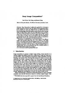
(a)
(b)
(c)
Fig. 1. The spatio-temporal domain: (a) Sample image with 5 scan-lines. (b) The 5 xt images associated with the 5 scan-lines. Each xt image accumulates its corresponding scan-line over the last 16 frames. The red lines separate between the xt images (c) The dual image of the 5 xt images, created by Hough transform. The large number of intersecting lines in the xt images is translated to a large number of points in the dual images. The red lines separate between the dual images.
and no particular pedestrian can be properly segmented for classification. In other cases, a single pedestrian at a distance is too small to be reliably and robustly detected in an image. Several pedestrian detection systems on moving vehicles were demonstrated in recent years [18], [1], [3]. All three systems focus on pedestrian detection and not crowd detection and all use a two step approach that combines stereo vision first followed by some classification or validation step. An interesting extension that combines appearance and motion was lately presented by [17]. The idea is to look at a pair of successive frames of a video sequence and search for a combination of appearance and motion cues. Good results were shown but again, it is assumed that pedestrians can be well segmented in the image. Crowd detection was investigated within the framework of static cameras (i.e. in train stations) where the idea is to use block-matching methods, similar to those used in MPEG, to measure the amount of motion, and hence “crowdiness”, in the scene. We can not carry over these ideas to our crowd detection module as we assume the host vehicle is moving. II. C ROWD D ETECTION Crowd detection is mainly required in dense urban settings where pedestrians often move in groups. These scenarios are extremely difficult to analyze because no individual pedestrian can be properly segmented out for detection, the path people take can be quite chaotic and the background is not homogenous and hence it is difficult to distinguish humans from man-made objects. Stereo matching is not enough either for detecting crowd since there might be many man-made objects that will have a similar 3D structure (i.e. poles, motorcycles). Single frame detection methods might be useful if the crowd is nearby but from a certain range the crowd becomes too small to be reliably detected from a single image and hence we resort to a motion-based approach.
Our crowd detection algorithm is based on spatiotemporal analysis of the video sequence, where we look for optic-flow patterns that can not be generated by a forward moving vehicle. A forward moving vehicle generates outward flow, hence inward flow must be generated by independently moving objects. This cue is strong enough to alert the system but is not enough do distinguish between a vehicle, a pedestrian or crowd. To further distinguish between the three classes we use higher level classifiers to determine if the object is a vehicle or pedestrian and an optic-flow analysis to determine is the moving region corresponds to a crowd. Inward motion in the input image give rise to a line in the spatio-temporal domain whose slope depends on the motion direction. When a group of people is moving in opposite directions they form a collection of intersecting lines in the spatio-temporal domain. The number of intersections formed by a crowd scene is usually high enough to distinguish between an inward moving vehicle or pedestrian and a crowd. In addition, detecting intersecting lines can be done robustly even for distant objects that exhibit small motions. The algorithm is based on xt slices in the spatio-temporal domain. A xt image is a single intensity scan-line collected over several frames (Fig 1). This representation is rich in information, easy to obtain and we will show that the relevant information can be calculated in real time. We use a variant of Hough transform to detect lines in the xt image. Only points with sufficient gradient in the xt image vote and the slope of the line passing through the points is taken to be perpendicular to the gradient of the point, in the xt image. To handle the case of a turning vehicle we have a “turning detection” module that tracks a sparse set of points in the image and determines if they all move in one direction. The crowd detection module updates its thresholds according to the output of the “turning detection” module. The algorithm observes several scan-lines in the image,
across multiple scales and detects inward moving objects and moving crowd. III. I MPLEMENTATION DETAILS The crowd detection algorithm is capable of detecting inward motion as well as collision between independently moving objects. After processing the input image, as described next, we obtain a probability distribution function for the inward motion (both left and right). We use hard thresholds on the probability distribution functions of the inward motion to determine if to raise the “inward motion” or “crowd detection” flags. We maintain a collection of 5 different scan-lines. For each scan-line we create a xt image that contains that scanline in the last 16 frames (the scan-line from the last image is at the bottom of the xt image) and keep such an image for each of the 4 levels of the Gaussian pyramid created from the input image. Thus, in total we have 20 xt images to maintain. The spacing of the scan-lines are based both on calculating distance on the road and distances in the image. The scan-lines can capture distant moving objects, according to the projection of the scan-line on the road. On the other hand, their position on the image plane ensures it will detect nearby objects as well. Moreover, the image spacing is dense enough so that every object will be detected by several scan-lines, adding to the robustness of the system. A. Detecting lines in the spatio-temporal domain A point (x, y) in an input image taken at time t is mapped to point (x, t) in the xt image. A moving object will form a line in the xt image and we will detect these lines using Hough transform. A point (x, t) in the xt image sits on any line given by t (1) x − x0 where a is the slope and x0 is the bias of the line (i.e. the point where the line intersects the bottom of the xt image). But by fixing the slope a to be perpendicular to the gradient of the point in the xt image we have a mapping from the xt image to its dual image, as given by the following formula: a=
dt dx (x0 , a) = f (x, t) ≡ (x + t, − ) (2) dx dt where dx and dt denotes the partial derivatives of the point (x, t). We use this derivation to map points in the original image to the dual of the xt image and we perform this operation only for points with high enough dx, dt gradients. The x axis in the dual image corresponds to the x axis in the original image and the y axis in the dual image corresponds to different motion velocities. In practice, we discretize the set of possible slopes a into 36 bins. Each point (x, t) with a strong enough gradient is mapped to a point (x0 , a) in the dual image and the gradient of the point in the xt image is added to the four nearest pixels in the dual image.
The above procedure assumes that lines in the xt image can be well detected. This assumption might be violated in case of fast motion that can create strong aliasing artifacts. To avoid this problem we construct the dual image for each of the 4 levels of the image pyramid and take the one with the highest level of fast outward moving objects. All further processing is done on this particular pyramid level. B. Inward motion We detect inward motion by breaking the dual image to left (positive slope) and right (negative slope) motion images, summing the columns and normalizing. This produces a probability distribution function for left and right motion. We detect inward motion if the probability of left motion in the right part of the image (or vice versa, right motion in the left part of the image) is above a predefined threshold. Finally, points of intersection are points with high left and right horizontal motion probabilities. Formally, let D be the dual image using the function defined in equation 2 then the left motion image L and right motion image R are given by � D(x0 , a) a > C L(x, a) = 0 a −C R(x, a) = D(x0 , a) a < −C where C is a threshold used to reduce noise effects. The probability that a pixel x on a scan-line is moving left is given by X pL (x) = L(x, a) a
And similarly, for the right motion we have: X pR (x) = R(x, a) a
if the probabilities of x to move both left and right (denoted, for short, by pL (x) and pR (x), respectively) are above some predefined threshold then x is a point of intersection. C. Making the final decision Crowd detection is determined as follows. First, inward motion threshold θx is calculated for each column x in the image. Then, zebra crossing is detected to increase or decrease system sensitivity and crowd detection is finally calculated. 1) Inward motion threshold: The threshold θx is determined differently if the vehicle is moving forward, rotating or standing still. By default, we set θx to reflect a forward moving vehicle. Then we determine if the vehicle is turning or standing still and change θx accordingly. Once θx is set we estimate inward motion by projecting all scan-lines on a single line and calculating, separately for left motion and right motion a histogram of all pixels pR (x) > θx and for all pixels pL (x) > θx . We then fit
(a)
(b)
Fig. 2. Examples with pedestrians: (a) Input images. (b) Corresponding graphs. The x-axis of the graph correspond to the position on the scan-line while the y-axis is a probability of that pixel. Red line denotes left motion, green line denotes right motion, yellow line denotes single-frame intersection score and the light blue line denotes the intersection score, averaged over time. As can be seen the light blue graph is high in all examples, indicating a strong “crowd detection” signal.
(a)
(b)
Fig. 3. Examples with no pedestrians: (a) Input images. (b) Corresponding graphs. The x-axis of the graph correspond to the position on the scan-line while the y-axis is a probability of that pixel. Red line denotes left motion, green line denotes right motion, yellow line denotes single-frame intersection score and the light blue line denotes the intersection score, averaged over time. As can be seen the light blue graph is very low in both cases indicating that no crowd is detected. In the first row one can see some right motion signal (denoted by the green line), this is due to the car on the opposite lane. In the second row there is a strong left motion caused by the white van on right that is entering the field of view. This is evident from the accompanying graph that shows a strong inward motion from the right (the red line).
the resulting histogram with a Gaussian mixture model and every large enough Gaussian is marked as an inward moving region whose width is given by the variance of the Gaussian. 2) Crowd detection: The “crowd detection” is based on the thresholding the product of the left and right motion histograms, weighted by an awareness factor that measures the probability of the scene to contain pedestrians. The awareness factor is based on the existence of zebra crossing, the number of detected vehicles and pedestrians in the scene, as well the speed of the vehicle. Thus, in dense urban settings the system is more sensitive to crowd detection wheres in highways it is almost impossible to trigger the “crowd detection” module. 3) Temporal smoothing: To further stabilize the system we use multi-frame smoothing. That is, we require that the signal will be detected for a minimum number of consecutive frames, before raising the flag. Similarly, we require that the signal will not be detected for a number of consecutive frames before turning off the flag. In case of “crowd detection” no further processing is needed, but in case of “inward motion” we pass the position and width of the suspected region to the pedestrian and vehicle detection modules as an additional cue. The information consists of the “inward motion” flag, as well as the width of the signal, as measured in the image. This information can
serve as a strong cue in discriminating between a vehicle and pedestrian. IV. E XPERIMENTS We use a progressive scan video camera that captures 30 frames per second at a resolution of 320 × 240 pixels. The camera is mounted on different vehicles and we only need to know the height of the camera from the ground, as well as its focal length for our application to work. No parameter was changed from one experiment to another. The images are fed to our development processing unit that consists of a single Motorola 1000 Mhz G4 processor that runs at about 15Hz. The processor performs vehicle detection, lane detection and pedestrian detection in addition to crowd detection. We are currently porting the development system to a specialized system-on-chip (EyeQ) with a target frame rate of 20-25Hz. The system can work with the video feed only, or it can connect to the car network to obtain various parameters such as speed and heading [14], [14], [13], [8]. In this paper we only describe the crowd detection module of a stand-alone system that is not connected to the car network. Fig 2 show experiments on scenes containing moving crowd. In each row we show the input image and the accompanying graph. The light blue line in the graph shows the amount of intersections detected, integrated over time.
The examples show crowd detection at different distances and, as can be seen, in all cases there is a strong intersection signal. Note, for example, that in the forth row, no individual pedestrian can be detected, but the crowd motion signal is quite strong. In Fig 3 we show experiments on scenes that do not contain crowd. The two examples show that in urban scenes that do not contain moving crowd the “crowd detection” signal (denoted by a light blue line) is nearly non-existent, as expected. On the other hand the system does detect some inward motion due to other moving vehicles in the environment. This information is passed to the vehicle detection module as a cue. V. S UMMARY
AND
C ONCLUSIONS
We have presented a system for crowd detection from a moving platform. The system uses slices in the spatiotemporal domain to detect inward motion as well as intersections between multiple moving objects. The spatiotemporal representation is easy to obtain and analyzed using Hough transform and quite stable using temporal smoothing. The system calculates probability distribution functions for left and right inward motion and use these probability distribution functions to infer a decision about inward motion or crowd detection. The system can automatically detect scenes that contain crowd consisting of multiple pedestrians moving in opposite directions, even at a large distance. In case the pedestrians are moving in a single direction, the system can detect inward motion and call the pedestrian and vehicle detection module for final verification. Experiments on real data show that the system can reliably detect crowd at distances of up to 70 meters and can robustly separate scenes with crowd from scenes that do not contain crowd. The inward motion detection capabilities are used in other applications, such as detecting crossing vehicles in intersections, or detecting single pedestrians, say children, that suddenly jump in front of the vehicle. Finally, there has been increased interest in infra-red (IR) video sensors. These sensors originated in military applications but are now finding their way into civilian applications. The idea of IR sensors is to detect the heat emitted by the body of pedestrians and discriminate the heat emitted by pedestrians from other heat sources, such as vehicles. Initial experiments suggest that the “crowd detection” algorithm works just as well on IR images. R EFERENCES [1] A. Broggi, M. Bertozzi, A. Fascoli and M. Sechi. “Shape-based pedestrian detection”. IEEE Intelligent Vehicle Symposium, pp 215220, Dearborn, U.S.A., 2000. [2] R. Cutler, L. Davis. “Real-time periodic motion detection, analysis and applications”. Proc. of IEEE Conference on Computer and Pattern Recognition, pp 326-331, Fort Collins, USA, 1999. [3] U. Franke, D. M. Gavrila, S. Gorzig, F. Lindner, F. Paetzold and C. Wohler. “Autonomous driving goes downtown”. IEEE Intelligent Systems, 13(6):40-48,1998. [4] D. M. Gavrila. “Protecting pedestrians in traffic: Sensor-based approaches”. IEEE Intelligent Systems, 2001.
[5] D. M. Gavrila. “The Visual Analysis of Human Movement: A Survey”. Computer Vision and Image Understanding, vol.73, no.1, pp.82-98, 1999, [6] I. Haritaoglu, D. Harwood, L. Davis. “W4-Real Time Detection and Tracking of People in 2.5D”. European Conference on Computer Vision, Germany, 1998. [7] P. Lombardi. “A survey on pedestrian detection for autonomous driving systems” Technical report 2001. [8] O. Mano, G. Stein, E. Dagan and A. Shashua. “Forward Collision Warning with a Single Camera”. IEEE Intelligent Vehicles Symposium (IV2004), June. 2004, Parma Italy. [9] S. A. Niyogi, E. H. Adelson. “Analyzing and Recognizing Walking Figures in xyt”. IEEE Conference on Computer Vision and Pattern Recognition, pp. 469-474, 1994. [10] C. Papageorgiou, T. Evgeniou, T. Poggio. “A trainable pedestrian detection system”. IEEE International Conference on Intelligent Vehicles, pp. 241-246, Germany, Oct 1998. [11] R. Polana and R. Nelson. “Low level recognition of human motion”. IEEE Workshop on Motion of Non-Rigid and Articulated Objects, pp. 77-82, Austin, 1994. [12] K. Rohr. “Towards Model-Based Recognition of Human Movement in Image Sequences”. CVGIP:Image Understanding, Vol. 59, No. 1, pp. 94-115, Jan, 1994. [13] A. Shashua, Y. Gdalyahu, G. Hayun and L. Mann. “Pedestrian Detection for Driving Assistance Systems”. IEEE Intelligent Vehicles Symposium (IV2004), June. 2004, Parma Italy. [14] G. P. Stein, O. Mano and A. Shashua. “A Robust Method for Computing Vehicle Ego-motion”. IEEE Intelligent Vehicles Symposium (IV2000), Oct. 2000, Dearborn, MI. [15] G. P. Stein, O. Mano and A. Shashua. “Vision-based ACC with a Single Camera: Bounds on Range and Range Rate Accuracy”. IEEE Intelligent Vehicles Symposium (IV2003),June 2003, Columbus, OH. [16] C. Wren, A. Azarbayejani, T. Darrell, A. Pentland. “Pfinder: Realtime Tracking of the Human Body”. IEEE Trans. on Pattern Analysis and Machine Intelligence, Vol. 19, No. 7, pp.780-785, July 1997. [17] P. Viola, M. Jones and D. Snow. “Detecting Pedestrians using Patterns of Motion Appearance”. IEEE International Conference on Computer Vision (ICCV), pp. 734-741, 2003. [18] L. Zhao and C. Thorpe. “Stereo- and neural network-based pedestrian detection”. IEEE Transactions on Intelligent Transportation Systems, 1(3), 2000.