Projects in VR Editors: Lawrence Rosenblum and Michael Macedonia
Cubic-Mouse-Based Interaction in Virtual Environments Bernd Fröhlich, John Plate, Jürgen Wind, Gerold Wesche, and Martin Göbel GMD National Research Center for Information Technology
I
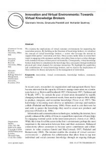
nteraction devices for virtual environments have evolved slowly. Most systems still employ tracked wands or some type of gloves, as in the first days of virtual reality systems. Only recently have prop-based interfaces in combination with two-handed interaction techniques become increasingly popular. Passive realworld props augment interaction through tactile feedback and often lead to more intuitive interaction techniques. The Cubic Mouse1,2 is a new, 3D input device based on the prop idea. It consists of a cube-shaped box with three perpendicular rods passing through its center (Figure 1). We use a six-degrees-of-freedom (6-DOF) tracker embedded in the Cubic Mouse to track the device’s position and orientation. The rods can be pushed and pulled, allowing the constrained input of three degrees of freedom. We call this “translation only” version the 3-DOF Cubic Mouse. Our latest version of the device, the 6-DOF Cubic Mouse, also allows rotation of the rods, which adds another three DOF. Altogether, we have a total of 12 analog degrees of freedom available with the Cubic Mouse, six DOF through the tracking and another six through the rods. These 12 DOF can be assigned to interaction tasks in various ways. In addition, the Cubic Mouse has six application-programma-
ble control buttons mounted on one face and one button at both ends of each rod.
Operating the device In this article we present a variety of interaction techniques developed around the Cubic Mouse, which we have implemented in various application prototypes. Our geo-scientific visualization system allows the exploration of data from the oil and gas industry in local and distributed virtual environments. With our automotive partners, we’re developing a system for steering and visualizing crash simulations. Other application areas include medical visualization and terrain visualization. All of these applications deal with the manipulation of a single virtual model (the reference model). The Cubic Mouse implements the idea of virtually holding the reference model in your hand. Navigation in this context entails rotating, translating, and zooming the reference model in contrast to flying, walking, or driving around—often the preferred method of navigation in walkthrough scenarios. The Cubic Mouse’s rods control virtual objects relative to the reference model. A few basic interaction techniques based on the Cubic Mouse became a standard for all of our applications: ■ The Cubic Mouse represents a reference model. All of
our models have up and down directions, and we assign the up direction to the Cubic Mouse’s face with the buttons. The cabling comes off the opposite face, which is thereby naturally assigned the down direction. Other directions align with the natural coordinate system that comes with the reference model. For example, the car model has a front, rear, left side, and right side. ■ We use the 6-DOF tracker inside the Cubic Mouse to position and orient the reference model, keeping the reference model’s orientation in sync with the orientation of the Cubic Mouse. For positioning tasks we use a 1:1 hand-to-model movement ratio on the Responsive Workbench and 1:3 to 1:5 ratios for larger display devices like a CAVE or Reality Center. A total of six buttons sit on the top face of the Cubic Mouse. A single button in one corner, two buttons in another corner, and three buttons in a third corner
1 The Cubic Mouse.
12
July/August 2000
0272-1716/00/$10.00 © 2000 IEEE
allow easy tactile identification of the associated functions. The single button serves as a clutch, allowing users to freeze the model in its current position. Releasing the clutch attaches the model to the Cubic Mouse’s current location and reorients it to the device’s orientation. The clutch also lets users move the model further than arm’s reach by extending the arm, releasing the model, moving the arm back, reattaching the model, extending the arm again, and so forth. The two buttons are used for zooming in and out. The three buttons are auxiliary buttons and have typically application-specific functionality. ■ The rods represent the X, Y, and Z axes of the reference model’s coordinate system. Tracking the Cubic Mouse ensures that the rods stay aligned with the coordinate system axes. Typically the rods are pushed and pulled to translate a virtual object like a cutting plane relative to the reference model in the appropriate direction. Rotating the rods is mostly used to rotate a virtual object around the corresponding axes of the reference model. ■ In most cases the buttons at the ends of each rod serve as a clutch for the rod. Moving the rod while pressing the button does not affect the position of the associated object. In other cases these buttons have application-specific functionality. ■ The origin for rotation and zoom operations is typically defined as the center of the model’s bounding sphere. After zooming and panning the model, it’s sometimes necessary to change the origin to a new location because it might have moved too far from the area of interest. Thus, by simultaneously pushing the two zoom buttons, users define the new origin as the position represented by the three rods, for example, the intersection point of three orthogonal cutting planes. From observations we found that in almost all cases users hold the device in their nondominant hand to position and orient the reference model, while their dominant hand operates the rods and the control buttons. Both hands are used only for larger rotations unachievable by just twisting the wrist of the nondominant hand.
1-DOF control—slicing and cutting The three rods can control a single degree of freedom of three independent objects. Visualization applications often use a set of three orthogonal planes—slicing or cutting—planes simultaneously. Figure 2 shows three orthogonal cross sections through a magnetic resonance imaging (MRI) data set of a human head. Each rod controls the position of a single slicing plane. In this scenario the rods’ rotations control small offset translations. The rotation of each rod typically controls ± 5% of the translation performed by moving the rod from stop to stop. Pushing and pulling the rod allows fast access to a certain region and roaming through the model. The rotation allows thorough investigation of a local area. In engineering applications three orthogonal cutting planes provide an important tool. Figure 3 shows an example of a chair cut of a finite-element model used
2 Using the Cubic Mouse to control three orthogonal cross sections through an MRI data set of a human head.
3
A chair cut of a finite element car model.
for car crash simulations. A chair cut removes one octant of the model, whereas three cutting planes cut away seven octants. These operations complement each other, and users can switch between them. The orientation of the cutting planes defines the octant being cut away or kept. The buttons mounted on both ends of each rod allow toggling the orientation of the corresponding cutting plane. In this crash visualization scenario the group of three application-specific buttons on top of the Cubic Mouse implement a video-player-like interface for playing back the crash sequence.
3-DOF control—translation For slicing and cutting operations the three rods control the position of three independent objects along a principal axis. We can also use the rods to control the 3D position of a single object within the reference model. We present two examples.
IEEE Computer Graphics and Applications
13
Projects in VR
Figure 4 shows a snapshot from our geo-scientific application prototype. One of the techniques used for the exploration of volumetric seismic data is a volumerendering lens. The rods control the position of the volume-rendering lens. The lens orientation is either (1) fixed and aligned with the data set or (2) it automatically orients itself toward the viewer. Figure 5 shows an oil well editing scenario, where a well path needs adjusting. The well trajectory is defined by a small set of interpolated control points, typically between 10 and 30 points. Two of the auxiliary buttons on the Cubic Mouse serve as up and down controls to select the current control point along the well path. The rods move the selected control point relative to its current location.
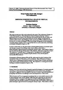
6-DOF control—translation and rotation The image sequence in Figure 6 shows a DaimlerChrysler S-Class car. The color-coded temperature distribution inside the car is visualized on an arbitrarily oriented slicing plane. The slicing plane represents one possibility for controlling translation and rotation of a
single object through the 6-DOF Cubic Mouse. Moving the rods moves the slicing plane in the corresponding direction. Twisting the rods rotates the slicing plane. The axis of rotation is defined by the center of the slicing plane and the direction of the rod used.
Integrating different interaction modes We developed our geo-scientific application prototype within the VRGeo consortium, which consists of oil and gas companies and software vendors, for this application domain. In oil and gas exploration the central data structure for most tasks is the seismic cube, a scalar volumetric grid representing subsurface structures. The Cubic Mouse literally puts the seismic cube into the user’s hands and allows intuitive control of position, orientation, and size of the data set. In this application we integrated four different interaction techniques that rely on the input from the three rods: ■ Three orthogonal seismic sections positioned in the
same way as for the medical scenario shown in Figure 2. ■ The volume-rendering lens shown in Figure 4. ■ Oil well editing as shown in Figure 5. ■ 6-DOF control of an arbitrarily oriented seismic slice similar to Figure 6. For cutting and slicing operations the resolution of a rod was, in general, sufficient to avoid clutching. Moving a rod from stop to stop moved the corresponding slice or cutting plane from one end to the other end of the data set. The rods’ positions serve as absolute inputs. This is no longer appropriate when the Cubic Mouse’s rods control multipe different objects, because it would cause objects to jump when switching control from one to the next. Therefore, we moved to a relative control mode, which also requires clutching of the rods. Each rod’s movement is transformed into a relative movement of the attached object. When arriving at one of the rod’s stops, one of the buttons at the end of the rod is pressed while moving the rod away from the stop. Clutching was only required for translating the rods. The rods allow up to 450 degrees of rotation, which provide enough cyclic overlap to avoid clutching for rotations in all of our applications.
4 The volumerendering lens (green frame) in a seismic data set.
Discussion and future work 5 Editing the trajectory of an oil well.
14
We have presented the Cubic Mouse to several hundred people during demonstrations and planned user observation sessions. We found that users became proficient with the device after only a few sentences of introduction. They immediately focused on the application and the task at hand, and didn’t have to concentrate on operating the Cubic Mouse. This direct understanding of the underlying interaction model
July/August 2000
results largely from the following: Tracking keeps the reference model aligned with the Cubic Mouse so that the rods always correspond to the principal axes of the reference model’s coordinate system. This visual cue in combination with the strong tactile cues provided by the Cubic Mouse’s shape make it easy and intuitive to find the desired rod without looking at the device. We have used the Cubic Mouse to control applications in a variety of virtual environment systems, for example, workbenches, caves, and large projection screens. In all these environments—and even for monoscopic displays and for applications with low frame rates, where it’s typically difficult to use tracked gloves or wands—we found that the Cubic Mouse performs well. At a recent public demonstration somebody suggested labeling the rods X, Y, and Z, and using the device to teach coordinate systems and transformations. We think this is a great idea. It shows that we have only begun to explore the full potential for this type of input device. In April 2000 we licensed the Cubic Mouse technology to Fakespace Systems. First production units of the device will become available later this year. ■
(a)
Acknowledgments This work was partially supported by the VRGeo, SimVR, and AutoBench consortia. We thank the members of the consortia for their valuable feedback during our meetings. Special thanks go to Lothar Muhlack for building the first prototype of the Cubic Mouse with rods that can be rotated. We also thank Ernst Kruijff, Jakob Beetz, Hartmut Seichter, Michael Tirtasana, and the VE group at GMD for their support.
6 Investigating the temperature distribution in a car model. The views show the car model and slicing plane from (a) the back, (b) the top, and (c, d) the side.
(b)
References 1. B. Fröhlich and J. Plate, “The Cubic Mouse: A New Device for 3D Input,” Proc. ACM CHI 2000, ACM Press, New York, Apr. 2000, pp. 526-531. 2. B. Fröhlich et al., “Exploring Geo-Scientific Data in Virtual Environments,” Proc. IEEE Visualization 1999, ACM Press, New York, Oct. 1999, pp. 169-173. 3. K. Hinckley, “Passive Real-World Interface Props for Neurosurgical Visualization,” Proc. ACM CHI 94 Conf. on Human Factors in Computing Systems, 1994, ACM Press, New York, pp. 452-458.
(c)
Contact Fröhlich at GMD/IMK, VE, Schloss Birlinghoven, D-53754 St. Augustin, Germany, e-mail
[email protected]. Contact department editors Rosenblum and Macedonia at
[email protected] and macedonia@ computer.org.
(d)
IEEE Computer Graphics and Applications
15