World Academy of Science, Engineering and Technology 79 2011
Current Controlled Current Conveyor (CCCII) and Application using 65nm CMOS Technology Zia Abbas, Giuseppe Scotti and Mauro Olivieri Abstract—Current mode circuits like current conveyors are getting significant attention in current analog ICs design due to their higher band-width, greater linearity, larger dynamic range, simpler circuitry, lower power consumption and less chip area. The second generation current controlled conveyor (CCCII) has the advantage of electronic adjustability over the CCII i.e. in CCCII; adjustment of the X-terminal intrinsic resistance via a bias current is possible. The presented approach is based on the CMOS implementation of second generation positive (CCCII+), negative (CCCII-) and dual Output Current Controlled Conveyor (DOCCCII) and its application as Universal filter. All the circuits have been designed and simulated using 65nm CMOS technology model parameters on Cadence Virtuoso / Spectre using 1V supply voltage. Various simulations have been carried out to verify the linearity between output and input ports, range of operation frequency, etc. The outcomes show good agreement between expected and experimental results.
II. DESCRIPTION OF CURRENT CONTROLLED CONVEYORS Fig. 1 and Fig. 2 show the symbol and equivalent circuit of the second generation Current Controlled Conveyor (CCCII). A CCCII-based circuit, whether positive, negative or dual output [3], provides electronic tunability and wide tunable range of its resistance at X-terminal [6]. The CCCII requires no external resistors; hence it is very suitable in the design of integrated filters and oscillators. Also, as the CCCII is current controlled current source, the CCCII based circuit is very suitable for high frequency operation. These features are very attractive to circuit designers [4].
Keywords—CCCII+,CCCII-,DOCCCII, Electronic tunability, Universal filter I.
C
INTRODUCTION
conveyor is a versatile current mode circuit, gaining acceptance as both a theoretical and practical building block. The current conveyor, with one high impedance input, one low impedance input and one high impedance output is a suitable element for both voltage-mode and current-mode circuits. The classical op-amps suffer from limited gain-bandwidth product problems and from low slew rate at its output. So, they remain unsatisfactory at higher frequencies. Moreover supply voltage has become the great concern in present electronic circuit design scenario especially for portable and battery powered equipment and the breakdown voltage of short channel MOS transistors. Since a low-voltage operating circuit becomes necessary, currentmode techniques are better suited for such purposes in comparison with voltage-mode ones. Consequently, currentmode circuits are receiving significant attention due to their larger dynamic range, higher band-width, greater linearity, simpler circuitry, lower power consumption, and reduced chip area as compared to their voltage mode counterparts like Operational Amplifiers. In recent years, due to the integration suitability with CMOS technology, current mode devices are finding even more consideration in circuit designs [1,2]. URRENT
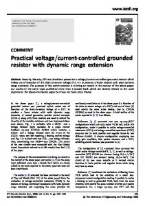
Fig.1: Symbol for CCCII
Fig.2 Eqivalent Circuit Diagram of CCCII
The relationship between the voltage and current variables at input and output ports X, Y and Z of the CCCII can be expressed by the following matrix, 1 0 0 0 0 1 0 0
Zia Abbas is with Department of Information, Electronics and Telecommunication Engineering (DIET), Sapienza University of Rome, Rome, Italy (
[email protected]). Giuseppe Scotti is with Department of Information, Electronics and Telecommunication Engineering (DIET), Sapienza University of Rome, Rome, Italy (
[email protected]). Mauro Olivieri is with Department of Information, Electronics and Telecommunication Engineering (DIET), Sapienza University of Rome, Rome, Italy (
[email protected]).
(1)
where the sign ± refers to plus-type or minus-type CCCII, respectively, and RX denotes the intrinsic resistance at X terminal. RX is adjustable by a supplied bias current Ib which can be expressed through a class AB trans-linear loop, which is used as input section.
935
World Academy of Science, Engineering and Technology 79 2011
0
(2) (3) (4) (5)
Resistance at X is given by (6) Where transistor.
is the physical parameter of the MOS Fig.3 CMOS based circuit of CCCII+
III. CMOS IMPLEMENTATION OF CCCII Fig. 3, 4, and 5 respectively show the schematics of conventional CMOS implementation of positive, negative and dual output current controlled conveyor (CCCII+, CCCII-, DOCCCII). We know that MOS-transistors in particular are more suitable for processing currents rather than voltages, because both in common-source and common-gate amplifier configurations the output signal is a current, while commondrain amplifier configuration are almost useless at low supply voltages because of the bulk-effect present in typical CMOSprocesses. Moreover, MOS current-mirrors are more accurate and less sensitive to process variation than bipolar currentmirrors because with the latter the base currents limit the accuracy. So, MOS-transistor circuits should be simplified by using current signals in preference to voltage signals. When the signal is conveyed as a current, the voltages in MOStransistor circuits are proportional to the square root of the signal, if saturation region operation is assumed for the devices [5,7]. Therefore, a compression of voltage signal swing and a reduction of supply voltage is possible. Also, with very high values for the drain currents of the MOS, their maximum usable frequency will be reached sooner. The circuit in Fig. 3 consists of one mixed trans-linear loop (transistors M1 to M4) as input cell. Two current mirrors (transistors M5, M6 and M7, M9) allow the mixed loop to be dc biased by the current Ib, the input cell present a high input impedance input port (Y) and a low impedance output port(X). This cell act as a voltage follower. The output Z that copies the current flowing through port X is realized in the conventional manner using two complementary mirror [4]. As shown in Fig. 4, current mirrors built up of M11,M12 & M15,M17 and M14,M16 & M10,M13 are cross coupling to generate negative current at Z. While in Fig. 5 generates both types of the output.
Fig.4 CMOS based circuit of CCCII-
Fig.5 CMOS based circuit of DOCCCII
936
World Academy of Science, Engineering and Technology 79 2011
IV. ANALYSIS OF CCCII
Transient analysis has been carried out with 100 MHz frequency sinusoidal input undistorted output. At frequencies higher than 100 MHz we may find phase shift in the output, so its actual range of frequency is around 100MHz. DC analysis has also been done to find the linearity between input and output ports. So in this way all three CCCII+, CCCII-, DOCCCII verified the current relationship equation i.e. Iz=+Ix, Iz=-Ix and Iz=±Ix respectively.
Fig. 6, 7, and 8 show the transient and AC analysis of CCCII+, CCCII- and DOCCCII respectively. AC analysis shows the range of frequency of operation and it indicates that current relationship is accurate up to 1GHz for all three CCCII circuits.
V. APPLICATION AS A UNIVERSAL FILTER CCCIIs are widely used as basic active building blocks to realize various current-mode active filters. The universal filter is among the most popular analog filters as it can provide several standard functions like low pass, high pass, band pass, band reject and all pass. In this section, a current mode universal filter has been implemented with single input and three different outputs for low, high and band pass filters. Implementation of Universal filter is shown in Fig.9 using only two DOCCCII and two capacitors, as the dual-output current conveyors is useful in the derivation of current-mode single input and three output filters using a reduced number of active components [8,9,10]. Previously, many realizations of current mode biquadratic filters using CCCIIs have been reported [10-17]. The analysis i.e. transfer function of the Universal filter can be summarized as follows,
Fig.6 Transient and AC analysis of CCCII+
2
1 1
1
(7) 1
2 1 2
1
2 1 2
1
2 1 2
⁄ 2
1 1
(8)
1
⁄ 2
1 1
1
(9)
Moreover, the band pass i.e. notch filter response can be obtained by connecting IHP and ILP together as follows. Fig.7: Transient and AC analysis of CCCII-
1
1
2 1 2
(10)
And similarly all pass filter transfer function can be implemented by connecting IHP, ILP and IBP together or IBR and IBP together as below. ⁄
Fig.8: Transient and AC analysis of DOCCCII
937
1 1
1
1
2 1 2
(11)
World Academy of Science, Engineering and Technology 79 2011
Fig.9 Current Mode Universal Filter using two DOCCCII Fig.11 Frequency Response of Notch Filter
The natural frequency
, the bandwidth
factor are given as,
and the Quality ⁄
1
(12)
1
(13) ⁄
(14)
Equations above clearly indicates that
and
can be
adjusted by the bias currents of Ib1 and Ib2 of the respective DOCCCII. Transmission of Universal filter is given by (15)
and in our implementation a2, a1 and a0 are 1, 1 and respectively. The following values of capacitors and bias currents have been used for the implementation of Universal filter.
Fig.12: Band Pass Filter response with variation in bias currents
Fig10 and Fig11 shows frequency responses for low, high & band pass filter and notch filter respectively. Fig12 shows the tunability in band pass filter as its response in changing with the variation in bias currents.After simulation with Virtuoso (Cadence) using 65nm CMOS parameters, we get the following results.
C1 = C2 = 250fF Ib1 = Ib2 = 2µA
TABLE I RESULTS ARE SHOWING GOOD RESPONSE AND RESEMBLES WITH THE EXPECTED VALUES
Band-width Peak Freq.
High Pass 31.9MHz 65.46 MHz
Low Pass 49.46 MHz 25.12 MHz
Band Pass 45.27 MHz 42.85 MHz
We also find the Quality factor 0.95.All results are showing good response and resembles with the expected values. VI. CONCLUSION We presented a CMOS implementation of CCCII+, CCCII-, DOCCCII circuit in 65nm CMOS technology. The design, based on a ±0.5V DC supply and developed using Virtuoso Cadence tool, achieves good linearity, low power dissipation and high bandwidth in the device. As an application we have
Fig.10 Frequency Response of Low, High and Band Pass Filters
938
World Academy of Science, Engineering and Technology 79 2011
simulated a current mode second order universal filter (Low Pass, High Pass, Band Pass, All Pass and Notch filters) using two DOCCCII and two capacitor showing a good agreement with expected results. REFERENCES [1] [2]
[3]
[4] [5] [6]
[7] [8]
[9]
[10]
[11]
[12]
[13]
[14]
[15]
[16]
[17]
C. Toumazou., F. J. Lidgey, and D. G. Haigh, Analogue IC design: the current-mode approach, London: Peter Peregrinus, 1990. D. R. Bhaskar, V. K. Sharma, M, Monis, and S. M. I. Rizvi, “New current-mode universal biquad filter,” Microelectronics Journal, vol. 30, pp. 837-839, 1999. Alain Fabre, Senior Member, IEEE, Omar Saaid, Francis Wiest, Member, IEEE, and Christophe Boucheron” High Frequency Applications Based on A new Current Controlled Conveyor” IEEE Transactions On Circuits And Systems-I: Fundamental Theory And Applications, Vol. 43, No. 2, February 1996. Sedra, K. C. Smith, "A second generation current conveyor and its application", IEE Trans. Circuit Theory, 1970, pp. 132-134. K. Smith and A. Sedra, “Microelectronic circuits,” pp. 368-569, 1999. A. Fabre, O. Saaid, F. Wiest, and C. Boucheron, “Current controllable bandpass filter based on translinear conveyors,” Electron. Lett, vol. 31, pp.1727–1728, 1995. Giuseppe Ferri, Nicola C. Guerrini ’Low voltage Low power CMOS Current Conveyors’ Kluwar Academic Publications, pp. 2-12. K. Ikeda and Y. Tomita, “Realization of current-mode biquadratic filter using CCIIs with current followers,” Electronics and Communications in Japan, part 2, vol. 77, pp. 99-107, 1994. A. M. Soliman, “New current mode filters using current conveyors,”International Journal of Electronics and Communication (AEU), vol. 51, pp. 275-278, 1997. N. A. Shah, M. F. Rather and S. Z. Iqbal “SITO electronically tunable high output impedance current mode Universal filter” April 2006 Springer Science – 2006. Winai Jaikla and Montree Siripruchyanun, “Current Controlled Current Conveyor-Based Current mode Universal Filter”, ISCIT'09 Proceedings of the 9th international conference on Communications and information technologies, pp 893-896, IEEE Press Piscataway, NJ, USA 2009. M.T Abuelma’atti and N.A. Tasadduq, “Universal current-controlled current-mode filter using the multiple-output translinear current conveyor,” Frequenz, vol. 52, pp. 252-254, 1998. Neeta Pandey, Sajal K. Paul and S.B.Jain, “A new electronically tunable current mode universal filter using MO-CCCII”, Analog Integrated Circuits for Signal Processing, 58, 171-178, 2009. E. Yuce, S. Minaei and O. Cicekoglu, “Universal current-mode active-C filter employing minimum number of passive elements,” Analog integrated circuits and signal Processing, vol. 42, pp. 169-171, 2006. S. Minaei and S. Türköz, “Current-mode electronically tunable universal filter using only plus-type current controlled conveyors and grounded capacitors,” ETRI Journal, vol.26, pp. 292-296, 2004. W. Tangsrirat and D. Prasertsom, “Electronically tunable low component count current-mode biquadratic filter using dual-output current followers,” Electrical Engineering, 2006. S. Minaei, O. Çiçekoglu, H. Kuntman, S. Türköz, “High output impedance current-mode lowpass, bandpass and highpass filters using current controlled conveyors,” International Journal of Electronics, vol. 88, pp. 915-922, 2001.
939