We want your new DirectLOGIC⢠automation equipment to operate safely. ... which the failure of the product could lead
D2–CTRINT Counter Interface Module Manual Number D2–CTRIF–M
WARNING Thank you for purchasing automation equipment from Automationdirect.com, doing business as, AutomationDirect. We want your new DirectLOGIC automation equipment to operate safely. Anyone who installs or uses this equipment should read this publication (and any other relevant publications) before installing or operating the equipment. To minimize the risk of potential safety problems, you should follow all applicable local and national codes that regulate the installation and operation of your equipment. These codes vary from area to area and usually change with time. It is your responsibility to determine which codes should be followed, and to verify that the equipment, installation, and operation are in compliance with the latest revision of these codes. At a minimum, you should follow all applicable sections of the National Fire Code, National Electrical Code, and the codes of the National Electrical Manufacturer’s Association (NEMA). There may be local regulatory or government offices that can also help determine which codes and standards are necessary for safe installation and operation. Equipment damage or serious injury to personnel can result from the failure to follow all applicable codes and standards. We do not guarantee the products described in this publication are suitable for your particular application, nor do we assume any responsibility for your product design, installation, or operation. Our products are not fault–tolerant and are not designed, manufactured or intended for use or resale as on–line control equipment in hazardous environments requiring fail–safe performance, such as in the operation of nuclear facilities, aircraft navigation or communication systems, air traffic control, direct life support machines, or weapons systems, in which the failure of the product could lead directly to death, personal injury, or severe physical or environmental damage (”High Risk Activities”). AutomationDirect specifically disclaims any expressed or implied warranty of fitness for High Risk Activities. For additional warranty and safety information, see the Terms and Conditions section of our Desk Reference. If you have any questions concerning the installation or operation of this equipment, or if you need additional information, please call us at 770–844–4200. This publication is based on information that was available at the time it was printed. At AutomationDirect we constantly strive to improve our products and services, so we reserve the right to make changes to the products and/or publications at any time without notice and without any obligation. This publication may also discuss features that may not be available in certain revisions of the product.
Trademarks This publication may contain references to products produced and/or offered by other companies. The product and company names may be trademarked and are the sole property of their respective owners. AutomationDirect disclaims any proprietary interest in the marks and names of others.
Copyright 2003, Automationdirect.com Incorporated All Rights Reserved No part of this manual shall be copied, reproduced, or transmitted in any way without the prior, written consent of Automationdirect.com Incorporated. AutomationDirect retains the exclusive rights to all information included in this document.
AVERTISSEMENT Nous vous remercions d’avoir acheté l’équipement d’automatisation de Automationdirect.comE, en faisant des affaires comme, AutomationDirect. Nous tenons à ce que votre nouvel équipement d’automatisation DirectLOGIC fonctionne en toute sécurité. Toute personne qui installe ou utilise cet équipement doit lire la présente publication (et toutes les autres publications pertinentes) avant de l’installer ou de l’utiliser. Afin de réduire au minimum le risque d’éventuels problèmes de sécurité, vous devez respecter tous les codes locaux et nationaux applicables régissant l’installation et le fonctionnement de votre équipement. Ces codes diffèrent d’une région à l’autre et, habituellement, évoluent au fil du temps. Il vous incombe de déterminer les codes à respecter et de vous assurer que l’équipement, l’installation et le fonctionnement sont conformes aux exigences de la version la plus récente de ces codes. Vous devez, à tout le moins, respecter toutes les sections applicables du Code national de prévention des incendies, du Code national de l’électricité et des codes de la National Electrical Manufacturer’s Association (NEMA). Des organismes de réglementation ou des services gouvernementaux locaux peuvent également vous aider à déterminer les codes ainsi que les normes à respecter pour assurer une installation et un fonctionnement sûrs. L’omission de respecter la totalité des codes et des normes applicables peut entraîner des dommages à l’équipement ou causer de graves blessures au personnel. Nous ne garantissons pas que les produits décrits dans cette publication conviennent à votre application particulière et nous n’assumons aucune responsabilité à l’égard de la conception, de l’installation ou du fonctionnement de votre produit. Nos produits ne sont pas insensibles aux défaillances et ne sont ni conçus ni fabriqués pour l’utilisation ou la revente en tant qu’équipement de commande en ligne dans des environnements dangereux nécessitant une sécurité absolue, par exemple, l’exploitation d’installations nucléaires, les systèmes de navigation aérienne ou de communication, le contrôle de la circulation aérienne, les équipements de survie ou les systèmes d’armes, pour lesquels la défaillance du produit peut provoquer la mort, des blessures corporelles ou de graves dommages matériels ou environnementaux (”activités à risque élevé”). La société AutomationDirect nie toute garantie expresse ou implicite d’aptitude à l’emploi en ce qui a trait aux activités à risque élevé. Pour des renseignements additionnels touchant la garantie et la sécurité, veuillez consulter la section Modalités et conditions de notre documentation. Si vous avez des questions au sujet de l’installation ou du fonctionnement de cet équipement, ou encore si vous avez besoin de renseignements supplémentaires, n’hésitez pas à nous téléphoner au 770–844–4200. Cette publication s’appuie sur l’information qui était disponible au moment de l’impression. À la société AutomationDirect, nous nous efforçons constamment d’améliorer nos produits et services. C’est pourquoi nous nous réservons le droit d’apporter des modifications aux produits ou aux publications en tout temps, sans préavis ni quelque obligation que ce soit. La présente publication peut aussi porter sur des caractéristiques susceptibles de ne pas être offertes dans certaines versions révisées du produit.
Marques de commerce La présente publication peut contenir des références à des produits fabriqués ou offerts par d’autres entreprises. Les désignations des produits et des entreprises peuvent être des marques de commerce et appartiennent exclusivement à leurs propriétaires respectifs. AutomationDirectE nie tout intérêt dans les autres marques et désignations. Copyright 2003, Automationdirect.comE Incorporated Tous droits réservés Nulle partie de ce manuel ne doit être copiée, reproduite ou transmise de quelque façon que ce soit sans le consentement préalable écrit de la société Automationdirect.comE Incorporated. AutomationDirect conserve les droits exclusifs à l’égard de tous les renseignements contenus dans le présent document.
1 Manual Revisions If you contact us in reference to this manual, be sure and include the revision number. Title: DL205 High Speed Counter Interface Manual, Rev B Manual Number: D2–CTRIF–M Issue
Date
Description of Changes
Original
10/94
Original Issue
Rev A
6/98
Minor corrections
2nd Edition
1/03
Upgrade for DL250–1/260 and rewritten for clarity
Rev A
3/03
Minor corrections
1 Table of Contents
i
Chapter 1: Getting Started Manual Introduction . . . . . . . . . . . . . . . . . . . . . . . . . . . . . . . . . . . . . . . . . . . . . . . . . . . . . . . . . . . . . . . . . The Purpose of this Manual . . . . . . . . . . . . . . . . . . . . . . . . . . . . . . . . . . . . . . . . . . . . . . . . . . . . . . . . . Supplemental Manuals . . . . . . . . . . . . . . . . . . . . . . . . . . . . . . . . . . . . . . . . . . . . . . . . . . . . . . . . . . . . . Who Should Read This Manual . . . . . . . . . . . . . . . . . . . . . . . . . . . . . . . . . . . . . . . . . . . . . . . . . . . . . Technical Support . . . . . . . . . . . . . . . . . . . . . . . . . . . . . . . . . . . . . . . . . . . . . . . . . . . . . . . . . . . . . . . . . Conventions Used . . . . . . . . . . . . . . . . . . . . . . . . . . . . . . . . . . . . . . . . . . . . . . . . . . . . . . . . . . . . . . . . . Key Topics for Each Chapter . . . . . . . . . . . . . . . . . . . . . . . . . . . . . . . . . . . . . . . . . . . . . . . . . . . . . . . . Module Overview . . . . . . . . . . . . . . . . . . . . . . . . . . . . . . . . . . . . . . . . . . . . . . . . . . . . . . . . . . . . . . . . . . . . Low–Cost Motion Control Solution . . . . . . . . . . . . . . . . . . . . . . . . . . . . . . . . . . . . . . . . . . . . . . . . . . . Typical Applications . . . . . . . . . . . . . . . . . . . . . . . . . . . . . . . . . . . . . . . . . . . . . . . . . . . . . . . . . . . . . . . Modes of Operation . . . . . . . . . . . . . . . . . . . . . . . . . . . . . . . . . . . . . . . . . . . . . . . . . . . . . . . . . . . . . . . Physical Characteristics . . . . . . . . . . . . . . . . . . . . . . . . . . . . . . . . . . . . . . . . . . . . . . . . . . . . . . . . . . . . . Input and Output Terminals . . . . . . . . . . . . . . . . . . . . . . . . . . . . . . . . . . . . . . . . . . . . . . . . . . . . . . . . . Module Indicators . . . . . . . . . . . . . . . . . . . . . . . . . . . . . . . . . . . . . . . . . . . . . . . . . . . . . . . . . . . . . . . . . Specifications . . . . . . . . . . . . . . . . . . . . . . . . . . . . . . . . . . . . . . . . . . . . . . . . . . . . . . . . . . . . . . . . . . . . . . . General . . . . . . . . . . . . . . . . . . . . . . . . . . . . . . . . . . . . . . . . . . . . . . . . . . . . . . . . . . . . . . . . . . . . . . . . . . Input Specifications . . . . . . . . . . . . . . . . . . . . . . . . . . . . . . . . . . . . . . . . . . . . . . . . . . . . . . . . . . . . . . . . Output Specifications . . . . . . . . . . . . . . . . . . . . . . . . . . . . . . . . . . . . . . . . . . . . . . . . . . . . . . . . . . . . . . Modes of Operation . . . . . . . . . . . . . . . . . . . . . . . . . . . . . . . . . . . . . . . . . . . . . . . . . . . . . . . . . . . . . . . . . Mode 10: Up Counter . . . . . . . . . . . . . . . . . . . . . . . . . . . . . . . . . . . . . . . . . . . . . . . . . . . . . . . . . . . . . . Mode 20: Standard or Quadrature Up/Down Counter (DL240/250–1/260 Only) . . . . . . . . . . . . . . Mode 30: Pulse Output (DL240/250–1/260 Only) . . . . . . . . . . . . . . . . . . . . . . . . . . . . . . . . . . . . . . . . Mode 40: External Interrupts . . . . . . . . . . . . . . . . . . . . . . . . . . . . . . . . . . . . . . . . . . . . . . . . . . . . . . . . Mode 50: Pulse Catch Inputs . . . . . . . . . . . . . . . . . . . . . . . . . . . . . . . . . . . . . . . . . . . . . . . . . . . . . . . Mode 60: Discrete Inputs with Filter . . . . . . . . . . . . . . . . . . . . . . . . . . . . . . . . . . . . . . . . . . . . . . . . . .
1–2 1–2 1–2 1–2 1–2 1–3 1–3 1–4 1–4 1–4 1–4 1–5 1–5 1–5 1–6 1–6 1–6 1–6 1–7 1–7 1–9 1–11 1–13 1–14 1–15
Chapter 2: Installation & Field Wiring Guidelines How to Install the Module . . . . . . . . . . . . . . . . . . . . . . . . . . . . . . . . . . . . . . . . . . . . . . . . . . . . . . . . . . . . Insert the Module . . . . . . . . . . . . . . . . . . . . . . . . . . . . . . . . . . . . . . . . . . . . . . . . . . . . . . . . . . . . . . . . . General Guidelines for Field Wiring . . . . . . . . . . . . . . . . . . . . . . . . . . . . . . . . . . . . . . . . . . . . . . . . . . . Wiring Diagram for Modes 10, 20, 40, 50 and 60 . . . . . . . . . . . . . . . . . . . . . . . . . . . . . . . . . . . . . . . . Wiring Diagram for Mode 30 . . . . . . . . . . . . . . . . . . . . . . . . . . . . . . . . . . . . . . . . . . . . . . . . . . . . . . . . . . Solid State Field Device Wiring . . . . . . . . . . . . . . . . . . . . . . . . . . . . . . . . . . . . . . . . . . . . . . . . . . . . . . . NPN Field Device Example . . . . . . . . . . . . . . . . . . . . . . . . . . . . . . . . . . . . . . . . . . . . . . . . . . . . . . . . . PNP Field Device Example . . . . . . . . . . . . . . . . . . . . . . . . . . . . . . . . . . . . . . . . . . . . . . . . . . . . . . . . .
2–2 2–2 2–3 2–4 2–4 2–5 2–5 2–5
Chapter 3: Mode 10 –High Speed UP Counters Using the UP Counters, Mode 10 . . . . . . . . . . . . . . . . . . . . . . . . . . . . . . . . . . . . . . . . . . . . . . . . . . . . . DL240/250–1/260 Applications . . . . . . . . . . . . . . . . . . . . . . . . . . . . . . . . . . . . . . . . . . . . . . . . . . . . . . DL230 Applications . . . . . . . . . . . . . . . . . . . . . . . . . . . . . . . . . . . . . . . . . . . . . . . . . . . . . . . . . . . . . . . . Understanding V-Memory Setup Locations . . . . . . . . . . . . . . . . . . . . . . . . . . . . . . . . . . . . . . . . . . . . Setting Up the CPU . . . . . . . . . . . . . . . . . . . . . . . . . . . . . . . . . . . . . . . . . . . . . . . . . . . . . . . . . . . . . . . . . . Configuring the V–Memory . . . . . . . . . . . . . . . . . . . . . . . . . . . . . . . . . . . . . . . . . . . . . . . . . . . . . . . . . Step 1: Entering the Selected Mode . . . . . . . . . . . . . . . . . . . . . . . . . . . . . . . . . . . . . . . . . . . . . . . . . Step 2: Select the Preset Mode (DL240/250–1/260 Only) . . . . . . . . . . . . . . . . . . . . . . . . . . . . . . . . . Step 3: Using Presets . . . . . . . . . . . . . . . . . . . . . . . . . . . . . . . . . . . . . . . . . . . . . . . . . . . . . . . . . . . . . . Triggering Presets to Outside Events . . . . . . . . . . . . . . . . . . . . . . . . . . . . . . . . . . . . . . . . . . . . . . . .
3–2 3–2 3–3 3–4 3–6 3–6 3–6 3–7 3–9 3–10
ii
Table of Contents Custom Configurations . . . . . . . . . . . . . . . . . . . . . . . . . . . . . . . . . . . . . . . . . . . . . . . . . . . . . . . . . . . . . . DL230 Custom Configuration . . . . . . . . . . . . . . . . . . . . . . . . . . . . . . . . . . . . . . . . . . . . . . . . . . . . . . . DL240/250–1/260 Custom Configuration . . . . . . . . . . . . . . . . . . . . . . . . . . . . . . . . . . . . . . . . . . . . . Writing the Control Program . . . . . . . . . . . . . . . . . . . . . . . . . . . . . . . . . . . . . . . . . . . . . . . . . . . . . . . . . Example 1: UP Counters Without Presets . . . . . . . . . . . . . . . . . . . . . . . . . . . . . . . . . . . . . . . . . . . . . Example 2: UP Counters with Multiple Presets . . . . . . . . . . . . . . . . . . . . . . . . . . . . . . . . . . . . . . . . Example 3: Speed Control for an AC Motor . . . . . . . . . . . . . . . . . . . . . . . . . . . . . . . . . . . . . . . . . . . . Example 4: Counting Pulses at a High Frequency Where Accuracy is Critical . . . . . . . . . . . . Troubleshooting . . . . . . . . . . . . . . . . . . . . . . . . . . . . . . . . . . . . . . . . . . . . . . . . . . . . . . . . . . . . . . . . . . . . . Things to check . . . . . . . . . . . . . . . . . . . . . . . . . . . . . . . . . . . . . . . . . . . . . . . . . . . . . . . . . . . . . . . . . . . Counter Doesn’t Count . . . . . . . . . . . . . . . . . . . . . . . . . . . . . . . . . . . . . . . . . . . . . . . . . . . . . . . . . . . . . No Input Signal . . . . . . . . . . . . . . . . . . . . . . . . . . . . . . . . . . . . . . . . . . . . . . . . . . . . . . . . . . . . . . . . . . . LED’s Do Not Light . . . . . . . . . . . . . . . . . . . . . . . . . . . . . . . . . . . . . . . . . . . . . . . . . . . . . . . . . . . . . . . . Non–Synchronous Pulsing . . . . . . . . . . . . . . . . . . . . . . . . . . . . . . . . . . . . . . . . . . . . . . . . . . . . . . . . . No Reset . . . . . . . . . . . . . . . . . . . . . . . . . . . . . . . . . . . . . . . . . . . . . . . . . . . . . . . . . . . . . . . . . . . . . . . . . Not Jumping to Interrupt . . . . . . . . . . . . . . . . . . . . . . . . . . . . . . . . . . . . . . . . . . . . . . . . . . . . . . . . . . . Not Returning from Interrupt . . . . . . . . . . . . . . . . . . . . . . . . . . . . . . . . . . . . . . . . . . . . . . . . . . . . . . . .
3–12 3–12 3–13 3–14 3–15 3–17 3–19 3–22 3–24 3–24 3–24 3–24 3–26 3–26 3–26 3–26 3–26
Chapter 4: Mode 20 –UP/DOWN Counter Using the UP/DOWN Counter, Mode 20 (DL240/250–1/260 Only) . . . . . . . . . . . . . . . . . . . . . . . . . UP/DOWN Counting Overview . . . . . . . . . . . . . . . . . . . . . . . . . . . . . . . . . . . . . . . . . . . . . . . . . . . . . . . . Encoders In General . . . . . . . . . . . . . . . . . . . . . . . . . . . . . . . . . . . . . . . . . . . . . . . . . . . . . . . . . . . . . . . Standard UP/DOWN Counting . . . . . . . . . . . . . . . . . . . . . . . . . . . . . . . . . . . . . . . . . . . . . . . . . . . . . . Quadrature UP/DOWN Counting . . . . . . . . . . . . . . . . . . . . . . . . . . . . . . . . . . . . . . . . . . . . . . . . . . . . How a Quadrature Encoder Works . . . . . . . . . . . . . . . . . . . . . . . . . . . . . . . . . . . . . . . . . . . . . . . . . . Understanding V-Memory Setup Locations . . . . . . . . . . . . . . . . . . . . . . . . . . . . . . . . . . . . . . . . . . . . Setting Up the CPU . . . . . . . . . . . . . . . . . . . . . . . . . . . . . . . . . . . . . . . . . . . . . . . . . . . . . . . . . . . . . . . . . . Configuring the V–Memory . . . . . . . . . . . . . . . . . . . . . . . . . . . . . . . . . . . . . . . . . . . . . . . . . . . . . . . . . Step 1: Entering the Mode Selected . . . . . . . . . . . . . . . . . . . . . . . . . . . . . . . . . . . . . . . . . . . . . . . . . Step 2: Select the Preset Mode . . . . . . . . . . . . . . . . . . . . . . . . . . . . . . . . . . . . . . . . . . . . . . . . . . . . . Step 3: The Presets . . . . . . . . . . . . . . . . . . . . . . . . . . . . . . . . . . . . . . . . . . . . . . . . . . . . . . . . . . . . . . . Loading the Presets . . . . . . . . . . . . . . . . . . . . . . . . . . . . . . . . . . . . . . . . . . . . . . . . . . . . . . . . . . . . . . . Using Negative Presets . . . . . . . . . . . . . . . . . . . . . . . . . . . . . . . . . . . . . . . . . . . . . . . . . . . . . . . . . . . . Triggering Presets to Outside Events . . . . . . . . . . . . . . . . . . . . . . . . . . . . . . . . . . . . . . . . . . . . . . . . The Other Channels . . . . . . . . . . . . . . . . . . . . . . . . . . . . . . . . . . . . . . . . . . . . . . . . . . . . . . . . . . . . . . . . . Filtered Input–Point 03 . . . . . . . . . . . . . . . . . . . . . . . . . . . . . . . . . . . . . . . . . . . . . . . . . . . . . . . . . . . . . Discrete Filtered Inputs . . . . . . . . . . . . . . . . . . . . . . . . . . . . . . . . . . . . . . . . . . . . . . . . . . . . . . . . . . . . Point 02 – Reset w/o an External Interrupt . . . . . . . . . . . . . . . . . . . . . . . . . . . . . . . . . . . . . . . . . . . . External Reset with Interrupt . . . . . . . . . . . . . . . . . . . . . . . . . . . . . . . . . . . . . . . . . . . . . . . . . . . . . . . . Custom Configurations . . . . . . . . . . . . . . . . . . . . . . . . . . . . . . . . . . . . . . . . . . . . . . . . . . . . . . . . . . . . . . Mode 20 Custom Configuring . . . . . . . . . . . . . . . . . . . . . . . . . . . . . . . . . . . . . . . . . . . . . . . . . . . . . . . Writing the Control Program for the UP/DOWN Counter . . . . . . . . . . . . . . . . . . . . . . . . . . . . . . . . Example 1: UP/DOWN Counting with an Interrupt . . . . . . . . . . . . . . . . . . . . . . . . . . . . . . . . . . . . . . Example 2: An UP/DOWN Counter with Standard Inputs . . . . . . . . . . . . . . . . . . . . . . . . . . . . . . . . Example 3: Quadrature Counting . . . . . . . . . . . . . . . . . . . . . . . . . . . . . . . . . . . . . . . . . . . . . . . . . . . . . Troubleshooting . . . . . . . . . . . . . . . . . . . . . . . . . . . . . . . . . . . . . . . . . . . . . . . . . . . . . . . . . . . . . . . . . . . . . What Can Go Wrong? . . . . . . . . . . . . . . . . . . . . . . . . . . . . . . . . . . . . . . . . . . . . . . . . . . . . . . . . . . . . . Counter Doesn’t Count . . . . . . . . . . . . . . . . . . . . . . . . . . . . . . . . . . . . . . . . . . . . . . . . . . . . . . . . . . . . . LED’s Do Not Light . . . . . . . . . . . . . . . . . . . . . . . . . . . . . . . . . . . . . . . . . . . . . . . . . . . . . . . . . . . . . . . . Non–Synchronous Pulsing . . . . . . . . . . . . . . . . . . . . . . . . . . . . . . . . . . . . . . . . . . . . . . . . . . . . . . . . . No Reset . . . . . . . . . . . . . . . . . . . . . . . . . . . . . . . . . . . . . . . . . . . . . . . . . . . . . . . . . . . . . . . . . . . . . . . . . Not Jumping to Interrupt . . . . . . . . . . . . . . . . . . . . . . . . . . . . . . . . . . . . . . . . . . . . . . . . . . . . . . . . . . . Not Returning from Interrupt . . . . . . . . . . . . . . . . . . . . . . . . . . . . . . . . . . . . . . . . . . . . . . . . . . . . . . . . Rotary Encoders . . . . . . . . . . . . . . . . . . . . . . . . . . . . . . . . . . . . . . . . . . . . . . . . . . . . . . . . . . . . . . . . . .
4–2 4–3 4–3 4–3 4–4 4–5 4–6 4–8 4–8 4–8 4–9 4–11 4–11 4–11 4–11 4–14 4–14 4–14 4–15 4–15 4–16 4–16 4–17 4–18 4–19 4–21 4–24 4–24 4–25 4–26 4–26 4–26 4–26 4–26 4–26
iii
Table of Contents
Chapter 5: Mode 30 –Pulse Train Outputs Using the Pulse Train Outputs, Mode 30 (DL240/250–1/260 only) . . . . . . . . . . . . . . . . . . . . . . . . D2–CTRINT Limitations . . . . . . . . . . . . . . . . . . . . . . . . . . . . . . . . . . . . . . . . . . . . . . . . . . . . . . . . . . . . . . Open Loop Stepper Motor System . . . . . . . . . . . . . . . . . . . . . . . . . . . . . . . . . . . . . . . . . . . . . . . . . . . Understanding V-Memory Setup Locations . . . . . . . . . . . . . . . . . . . . . . . . . . . . . . . . . . . . . . . . . . . . Default Settings . . . . . . . . . . . . . . . . . . . . . . . . . . . . . . . . . . . . . . . . . . . . . . . . . . . . . . . . . . . . . . . . . . . Setting Up the CPU . . . . . . . . . . . . . . . . . . . . . . . . . . . . . . . . . . . . . . . . . . . . . . . . . . . . . . . . . . . . . . . . . . Configuring the V–Memory . . . . . . . . . . . . . . . . . . . . . . . . . . . . . . . . . . . . . . . . . . . . . . . . . . . . . . . . . Assigning Module Functions . . . . . . . . . . . . . . . . . . . . . . . . . . . . . . . . . . . . . . . . . . . . . . . . . . . . . . . . Custom Configurations . . . . . . . . . . . . . . . . . . . . . . . . . . . . . . . . . . . . . . . . . . . . . . . . . . . . . . . . . . . . . . Custom Options for Mode 30 . . . . . . . . . . . . . . . . . . . . . . . . . . . . . . . . . . . . . . . . . . . . . . . . . . . . . . . Determine the Positioning Profile . . . . . . . . . . . . . . . . . . . . . . . . . . . . . . . . . . . . . . . . . . . . . . . . . . . . . Automatic Accel/Decel Trapezoid Profile . . . . . . . . . . . . . . . . . . . . . . . . . . . . . . . . . . . . . . . . . . . . . Understanding the Positioning Profile of Setup Locations . . . . . . . . . . . . . . . . . . . . . . . . . . . . . . Y4 use in the Absolute Mode: Bit 15 of V3630 set to 0 . . . . . . . . . . . . . . . . . . . . . . . . . . . . . . . . . Y4 use in the Incremental Mode: Bit 15 of V3630 set to 1 . . . . . . . . . . . . . . . . . . . . . . . . . . . . . . Y4 use with an Interrupt –Bit 12 of V3630 set to 1 . . . . . . . . . . . . . . . . . . . . . . . . . . . . . . . . . . . . . Actual Count V1175/V1174 . . . . . . . . . . . . . . . . . . . . . . . . . . . . . . . . . . . . . . . . . . . . . . . . . . . . . . . . . The Automatic Accel/Decel Profile . . . . . . . . . . . . . . . . . . . . . . . . . . . . . . . . . . . . . . . . . . . . . . . . . . . . Configuring V-Memory for the Method of Your Choice . . . . . . . . . . . . . . . . . . . . . . . . . . . . . . . . . . Step 1: Setup V3630 . . . . . . . . . . . . . . . . . . . . . . . . . . . . . . . . . . . . . . . . . . . . . . . . . . . . . . . . . . . . . . . Step 2: Set the Target Pulse Count and Shaft Direction . . . . . . . . . . . . . . . . . . . . . . . . . . . . . . . . . Step 3: Set the Starting Velocity . . . . . . . . . . . . . . . . . . . . . . . . . . . . . . . . . . . . . . . . . . . . . . . . . . . . . Step 4: Entering the Acceleration Time . . . . . . . . . . . . . . . . . . . . . . . . . . . . . . . . . . . . . . . . . . . . . . . Step 5: Entering the Deceleration Time . . . . . . . . . . . . . . . . . . . . . . . . . . . . . . . . . . . . . . . . . . . . . . . The Step Trapezoid Profile . . . . . . . . . . . . . . . . . . . . . . . . . . . . . . . . . . . . . . . . . . . . . . . . . . . . . . . . . . . Configuring V-Memory . . . . . . . . . . . . . . . . . . . . . . . . . . . . . . . . . . . . . . . . . . . . . . . . . . . . . . . . . . . . . Step Trapezoidal Profile Example . . . . . . . . . . . . . . . . . . . . . . . . . . . . . . . . . . . . . . . . . . . . . . . . . . . Step 1: Setup V3630 . . . . . . . . . . . . . . . . . . . . . . . . . . . . . . . . . . . . . . . . . . . . . . . . . . . . . . . . . . . . . . . Step 2: Setup the Target Pulse Count . . . . . . . . . . . . . . . . . . . . . . . . . . . . . . . . . . . . . . . . . . . . . . . . Step 3: Select the Height and Width . . . . . . . . . . . . . . . . . . . . . . . . . . . . . . . . . . . . . . . . . . . . . . . . . Step 4: Enter the Step Information Into Memory . . . . . . . . . . . . . . . . . . . . . . . . . . . . . . . . . . . . . . . Ladder Logic Example . . . . . . . . . . . . . . . . . . . . . . . . . . . . . . . . . . . . . . . . . . . . . . . . . . . . . . . . . . . . . The Straight Velocity Profile . . . . . . . . . . . . . . . . . . . . . . . . . . . . . . . . . . . . . . . . . . . . . . . . . . . . . . . . . . Configuring V-Memory . . . . . . . . . . . . . . . . . . . . . . . . . . . . . . . . . . . . . . . . . . . . . . . . . . . . . . . . . . . . . Step 1: Setup V3630 . . . . . . . . . . . . . . . . . . . . . . . . . . . . . . . . . . . . . . . . . . . . . . . . . . . . . . . . . . . . . . . Step 2: Set the Direction for Shaft Rotation . . . . . . . . . . . . . . . . . . . . . . . . . . . . . . . . . . . . . . . . . . . Step 3: Set Shaft Velocity . . . . . . . . . . . . . . . . . . . . . . . . . . . . . . . . . . . . . . . . . . . . . . . . . . . . . . . . . . Velocity Control Used to Find the Home Position . . . . . . . . . . . . . . . . . . . . . . . . . . . . . . . . . . . . . . Straight Velocity Profile Example . . . . . . . . . . . . . . . . . . . . . . . . . . . . . . . . . . . . . . . . . . . . . . . . . . . . What Happens If the Ramping and Target Are Mismatched? . . . . . . . . . . . . . . . . . . . . . . . . . . . . Activating the Positioning Profile . . . . . . . . . . . . . . . . . . . . . . . . . . . . . . . . . . . . . . . . . . . . . . . . . . . . . Putting It All Together . . . . . . . . . . . . . . . . . . . . . . . . . . . . . . . . . . . . . . . . . . . . . . . . . . . . . . . . . . . . . . . A Complete Program . . . . . . . . . . . . . . . . . . . . . . . . . . . . . . . . . . . . . . . . . . . . . . . . . . . . . . . . . . . . . . Graphical Diagram of Positioning Profile . . . . . . . . . . . . . . . . . . . . . . . . . . . . . . . . . . . . . . . . . . . . . . The External Interrupt at X1 . . . . . . . . . . . . . . . . . . . . . . . . . . . . . . . . . . . . . . . . . . . . . . . . . . . . . . . . . . How It Works . . . . . . . . . . . . . . . . . . . . . . . . . . . . . . . . . . . . . . . . . . . . . . . . . . . . . . . . . . . . . . . . . . . . . Memory When Using the Interrupt . . . . . . . . . . . . . . . . . . . . . . . . . . . . . . . . . . . . . . . . . . . . . . . . . . . Troubleshooting . . . . . . . . . . . . . . . . . . . . . . . . . . . . . . . . . . . . . . . . . . . . . . . . . . . . . . . . . . . . . . . . . . . . . Is The Module Working Properly? . . . . . . . . . . . . . . . . . . . . . . . . . . . . . . . . . . . . . . . . . . . . . . . . . . . CW and CCW Indicators . . . . . . . . . . . . . . . . . . . . . . . . . . . . . . . . . . . . . . . . . . . . . . . . . . . . . . . . . . . I/O Indicators 00 through 01 . . . . . . . . . . . . . . . . . . . . . . . . . . . . . . . . . . . . . . . . . . . . . . . . . . . . . . . . Verify Stepper Motor Rotation . . . . . . . . . . . . . . . . . . . . . . . . . . . . . . . . . . . . . . . . . . . . . . . . . . . . . . . Verify Calculations . . . . . . . . . . . . . . . . . . . . . . . . . . . . . . . . . . . . . . . . . . . . . . . . . . . . . . . . . . . . . . . . . Motor Overshoot and Stalls . . . . . . . . . . . . . . . . . . . . . . . . . . . . . . . . . . . . . . . . . . . . . . . . . . . . . . . . .
5–2 5–3 5–3 5–5 5–6 5–7 5–7 5–8 5–9 5–9 5–10 5–10 5–12 5–12 5–12 5–13 5–13 5–14 5–14 5–15 5–15 5–16 5–16 5–16 5–18 5–18 5–19 5–20 5–20 5–21 5–22 5–23 5–25 5–25 5–25 5–25 5–26 5–26 5–26 5–28 5–30 5–31 5–31 5–36 5–37 5–38 5–39 5–40 5–40 5–40 5–41 5–41 5–41 5–41
iv
Table of Contents
Chapter 6: Mode 40 –High Speed Interrupts Using the Interrupt Inputs, Mode 40 . . . . . . . . . . . . . . . . . . . . . . . . . . . . . . . . . . . . . . . . . . . . . . . . . . . High Speed Interrupts . . . . . . . . . . . . . . . . . . . . . . . . . . . . . . . . . . . . . . . . . . . . . . . . . . . . . . . . . . . . . . High Speed Interrupts Process . . . . . . . . . . . . . . . . . . . . . . . . . . . . . . . . . . . . . . . . . . . . . . . . . . . . . . . Single Input Signal Processing . . . . . . . . . . . . . . . . . . . . . . . . . . . . . . . . . . . . . . . . . . . . . . . . . . . . . . Multiple Signals from Same Input . . . . . . . . . . . . . . . . . . . . . . . . . . . . . . . . . . . . . . . . . . . . . . . . . . . . Simultaneous Skeans from Different Inputs . . . . . . . . . . . . . . . . . . . . . . . . . . . . . . . . . . . . . . . . . . . Leading Edge Triggering . . . . . . . . . . . . . . . . . . . . . . . . . . . . . . . . . . . . . . . . . . . . . . . . . . . . . . . . . . . Understanding V-Memory Setup Locations . . . . . . . . . . . . . . . . . . . . . . . . . . . . . . . . . . . . . . . . . . . . Default Settings . . . . . . . . . . . . . . . . . . . . . . . . . . . . . . . . . . . . . . . . . . . . . . . . . . . . . . . . . . . . . . . . . . . Explanation the Values . . . . . . . . . . . . . . . . . . . . . . . . . . . . . . . . . . . . . . . . . . . . . . . . . . . . . . . . . . . . . Custom Configuration . . . . . . . . . . . . . . . . . . . . . . . . . . . . . . . . . . . . . . . . . . . . . . . . . . . . . . . . . . . . . . . Setting Up the CPU for the Interrupts . . . . . . . . . . . . . . . . . . . . . . . . . . . . . . . . . . . . . . . . . . . . . . . . . Configuring the V–Memory . . . . . . . . . . . . . . . . . . . . . . . . . . . . . . . . . . . . . . . . . . . . . . . . . . . . . . . . . Step 1: Enter the Mode . . . . . . . . . . . . . . . . . . . . . . . . . . . . . . . . . . . . . . . . . . . . . . . . . . . . . . . . . . . . Step 2: How Many Interrupts . . . . . . . . . . . . . . . . . . . . . . . . . . . . . . . . . . . . . . . . . . . . . . . . . . . . . . . . Step 3: Configure the V-Memory . . . . . . . . . . . . . . . . . . . . . . . . . . . . . . . . . . . . . . . . . . . . . . . . . . . . Two Types of Interrupts . . . . . . . . . . . . . . . . . . . . . . . . . . . . . . . . . . . . . . . . . . . . . . . . . . . . . . . . . . . . Troubleshooting . . . . . . . . . . . . . . . . . . . . . . . . . . . . . . . . . . . . . . . . . . . . . . . . . . . . . . . . . . . . . . . . . . . . . Interrupt Device Working But No Interrupt . . . . . . . . . . . . . . . . . . . . . . . . . . . . . . . . . . . . . . . . . . . . Interrupt Occurs, But No Normal Scan Afterwards . . . . . . . . . . . . . . . . . . . . . . . . . . . . . . . . . . . . .
6–2 6–3 6–4 6–4 6–4 6–5 6–5 6–6 6–7 6–7 6–8 6–9 6–9 6–9 6–10 6–10 6–11 6–13 6–13 6–13
Chapter 7: Mode 50 –Pulse Catch Inputs Using the Pulse Catch Inputs, Mode 50 . . . . . . . . . . . . . . . . . . . . . . . . . . . . . . . . . . . . . . . . . . . . . . . Pulse Catching Explained . . . . . . . . . . . . . . . . . . . . . . . . . . . . . . . . . . . . . . . . . . . . . . . . . . . . . . . . . . Understanding V-Memory Setup Locations . . . . . . . . . . . . . . . . . . . . . . . . . . . . . . . . . . . . . . . . . . . . Default Settings . . . . . . . . . . . . . . . . . . . . . . . . . . . . . . . . . . . . . . . . . . . . . . . . . . . . . . . . . . . . . . . . . . . Custom Configuration . . . . . . . . . . . . . . . . . . . . . . . . . . . . . . . . . . . . . . . . . . . . . . . . . . . . . . . . . . . . . . . Setting UP the CPU for the Pulse Catch Inputs . . . . . . . . . . . . . . . . . . . . . . . . . . . . . . . . . . . . . . . . Configuring the V–Memory . . . . . . . . . . . . . . . . . . . . . . . . . . . . . . . . . . . . . . . . . . . . . . . . . . . . . . . . . Step 1: Enter the Mode Selected . . . . . . . . . . . . . . . . . . . . . . . . . . . . . . . . . . . . . . . . . . . . . . . . . . . . Step 2: How Many Pulse Catch Inputs . . . . . . . . . . . . . . . . . . . . . . . . . . . . . . . . . . . . . . . . . . . . . . . Step 3: Configure the V-Memory . . . . . . . . . . . . . . . . . . . . . . . . . . . . . . . . . . . . . . . . . . . . . . . . . . . . Troubleshooting . . . . . . . . . . . . . . . . . . . . . . . . . . . . . . . . . . . . . . . . . . . . . . . . . . . . . . . . . . . . . . . . . . . . .
7–2 7–3 7–4 7–5 7–6 7–7 7–7 7–7 7–8 7–8 7–10
Chapter 8: Mode 60 –Discrete/Filter Inputs Using the Discrete Filtered Inputs, Mode 60 . . . . . . . . . . . . . . . . . . . . . . . . . . . . . . . . . . . . . . . . . . . Discrete Filtered Inputs . . . . . . . . . . . . . . . . . . . . . . . . . . . . . . . . . . . . . . . . . . . . . . . . . . . . . . . . . . . . Understanding V-Memory Setup Locations . . . . . . . . . . . . . . . . . . . . . . . . . . . . . . . . . . . . . . . . . . . . Default Settings . . . . . . . . . . . . . . . . . . . . . . . . . . . . . . . . . . . . . . . . . . . . . . . . . . . . . . . . . . . . . . . . . . . Custom Configuration . . . . . . . . . . . . . . . . . . . . . . . . . . . . . . . . . . . . . . . . . . . . . . . . . . . . . . . . . . . . . . . Setting Up the CPU for Discrete Filtered Inputs . . . . . . . . . . . . . . . . . . . . . . . . . . . . . . . . . . . . . . . . Configuring the V–Memory . . . . . . . . . . . . . . . . . . . . . . . . . . . . . . . . . . . . . . . . . . . . . . . . . . . . . . . . . Step 1: Enter the Mode . . . . . . . . . . . . . . . . . . . . . . . . . . . . . . . . . . . . . . . . . . . . . . . . . . . . . . . . . . . . Step 2: How many Channels . . . . . . . . . . . . . . . . . . . . . . . . . . . . . . . . . . . . . . . . . . . . . . . . . . . . . . . . Step 3: Configure the V-Memory. . . . . . . . . . . . . . . . . . . . . . . . . . . . . . . . . . . . . . . . . . . . . . . . . . . . . Troubleshooting . . . . . . . . . . . . . . . . . . . . . . . . . . . . . . . . . . . . . . . . . . . . . . . . . . . . . . . . . . . . . . . . . . . . .
8–2 8–3 8–4 8–5 8–6 8–7 8–7 8–7 8–8 8–8 8–10
Getting Started
In This Chapter. . . .
11
Ċ Introduction Ċ Physical Characteristics Ċ Specifications Ċ Modes of Operation Ċ Motion Control Made Easy - Four Simple Steps
1–2 Getting Started
Getting Started
Manual Introduction The Purpose of this Manual
This manual describes the installation of the D2–CTRINT Counter Interface Module, and how to select the operating modes of the high–speed counting features. It also shows shows several ways to use the data in a PLC program.
Supplemental Manuals
The following manuals are essential for the proper use of your DL05 DeviceNet Slave Module. S DL205 PLC User Manual part number D2–USER–M This manual contains detailed descriptions of the instructions used to setup and control the counter module. It also contains the complete I/O Memory Map which will be helpful. S The DirectSOFT32 Programmer Software Users Manual If you understand the DL205 instruction set and system setup requirements, this manual will provide the information you need to install and use the Counter Interface Module. This manual is not intended to be a tutorial on motion control theory, but rather a user reference manual for the D2-CTRINT Counter Interface Module.
Who Should Read This Manual
Technical Support
We strive to make our manuals the best in the industry and rely on your feedback in reaching our goal. If you cannot find the solution to your particular application, or, if for any reason you need additional technical assistance, please call us at 770–844–4200. Our technical support team is glad to work with you in answering your questions. They are available weekdays from 9:00 a.m. to 6:00 p.m. Eastern Time. We also encourage you to visit our website where you can find technical and nontechnical information about our products and our company. www.automationdirect.com
DL205 High Speed Counter Interface Manual, 2nd Ed, Rev. A
1–3 Getting Started
Conventions Used
The “note pad” icon in the left–hand margin indicates a special note.
The “exclamation mark” icon in the left-hand margin indicates a warning or caution. These are very important because the information may help you prevent serious personal injury or equipment damage. Key Topics for Each Chapter
The beginning of each chapter will list the key topics that can be found in that chapter.
1
DL205 High Speed Counter Interface Manual, 2nd Ed, Rev. A
Getting Started
The “light bulb” icon in the left-hand margin indicates a tip or shortcut.
1–4 Getting Started
Getting Started
Module Overview Low–Cost Motion Control Solution
Typical Applications
Modes of Operation
Many machine control applications require various types of simple high-speed control. These applications usually involve some type of motion control, or high-speed interrupts for time-critical events. The DL205 product family solves this traditionally expensive problem with built-in CPU features which are accessed by the D2-CTRINT, Counter Interface Module.
CW CCW
D2
The Counter Interface Module is well suited for monitoring and controlling various types of high-speed input signals (pulses) which cannot be measured with standard discrete input modules. The Counter Interface Module works with a special part of the DL205 CPU which operates independently of the CPU program scan. This provides the accurate measurement and capturing of high-speed pulses, short duration discrete inputs, etc. The pulses can be provided from several different devices, such as, pulse encoders, sensors and limit switches. A typical application is an encoder which is connected to a rotating device. The encoders produce a given number of pulses for each rotation of the shaft, so control decisions can be made based on the number of pulses counted. The D2–CTRINT module operates at up to 5 KHz and allows you to access several different counting options. These counter features are built into the CPU, but the Counter Interface Module must be used to connect these features to a particular process. There are several options available: S High Speed counter with up to 24 presets and built-in interrupt subroutines S Quadrature encoder input to measure counts and clockwise or counter clockwise direction S Programmable pulse output with external interrupts and separate acceleration and deceleration profiles for positioning and velocity control S External interrupt inputs for immediate response to critical or time sensitive tasks S Pulse catch feature to read up to 4 inputs, with each input having a pulse width as small as 0.1ms S Programmable discrete filtering (both on and off delay up to 99ms) to ensure input signal integrity
DL205 High Speed Counter Interface Manual, 2nd Ed, Rev. A
1–5 Getting Started
Physical Characteristics The D2–CTRINT, Counter Interface Module, is an interface for several counting methods. It also provides a means to use embedded features of the CPU for interrupt, pulse catching, pulse output and discrete input. As a result, the module has both input and output terminals. Sometimes the same terminals are used as inputs in one mode and outputs in a different mode. The terminal block can be removed for ease of wiring. There are pinch tabs on the top and bottom of the terminal block. To remove the terminal block, squeeze the pinch tabs and pull the terminal block from the module. WARNING: Field device power may still be present on the terminal block even though the power has been disconnected from the PLC system. To minimize the risk of electrical shock, check all field device power before removing the connector.
0 1 2 3 D2-CTRINT
CNTR I/F CW CCW
0 C0
I/O 00
I/O C0
1 C1 2 C2
01
C1
3 C3 4
02
Module Indicators
C2
C4
03
C3
04
C4
The Counter Interface Module also has LEDs to indicate the module operation. The module has four indicators: one for each input, one for clockwise and one for counter clockwise operation (for those modes which use direction.)
0 1
CNTR I/F CW CCW
2 3
DL205 High Speed Counter Interface Manual, 2nd Ed, Rev. A
Getting Started
Input and Output Terminals
1–6 Getting Started
Getting Started
Specifications The following tables provide specifications for the Counter Interface Module. General
Input Specifications
Output Specifications
Modules per System
1 only
Module Type
Discrete Input/Pulse Output
Installation Requirements
Must install in slot 0, next to CPU
Power Budget Requirement
200mA, 5 VDC (from base)
Digital I/O Consumed Input Points Output Points
8 input points (X0–X7) 8 output points (Y0–Y7)
Field Wiring
Standard 8pt. removable terminal block
Operating Temperature
32 to 131° F (0 to 55_ C)
Storage Temperature
–4 to 158° F (–20 to 70_ C)
Relative Humidity
30 to 95% (non-condensing)
Environmental air
No corrosive gases permitted
Vibration
MIL STD 810C 514.2
Shock
MIL STD 810C 516.2
Noise Immunity
NEMA ICS3–304
Input
4 points, current sink/source, 5KHz maximum
Minimum Pulse Width
100ms (0.1ms)
Input Voltage Range
12 or 24 VDC "15%
Maximum Voltage
30 VDC
Rated Input Current
10mA typical, 13mA maximum
Minimum ON Voltage
8.0 VDC
Maximum OFF Voltage
1.0 VDC
Minimum ON Current
8.0mA
Maximum OFF Current
1.0mA
OFF to ON Response
Less than 30ms
ON to OFF Response
Less than 30ms
Output
2 points, current sinking, 5KHz maximum
External Power Supply Requirements
5.0 VDC"10%
Output Voltage Range
5.0 VDC "15%
Maximum Voltage
5.5 VDC
Maximum Load Current
30mA
Minimum Load Voltage
4.5 VDC
Leakage Current
Less than 0.1mA at 5.5 VDC
Inrush Current
0.5A (for 10ms)
OFF to ON Response
Less than 30ms
ON to OFF Response
Less than 30ms
DL205 High Speed Counter Interface Manual, 2nd Ed, Rev. A
1–7 Getting Started
Modes of Operation
Counting Input Pulses
Encoder Count Up Output
Each of the 24 presets has a special relay which is used to trigger events whenever the preset equals the current value. Absolute presets can be used to compare the preset directly to the current count, or incremental presets can be used to compare the current count to the current preset plus the accumulated value of the previous presets. The subroutine can be programmed to perform whatever tasks are necessary. For example, Immediate I/O instructions can be used in the interrupt subroutine to provide a very fast response. Once the interrupt execution is complete, the CPU resumes normal program execution from the point where the interrupt occurred. Turning the ENABLE of the counter ON and OFF will start and halt the counting. There are three ways to reset the counters, (1) signal sent from an input module to the CPU where the input is read during the normal scan update, (2) signal sent directly into the module via point 02 and/or point 03, and (3) using an internal relay of the PLC to perform the reset via the program. The second choice is the quickest reset. This module remains an OPEN LOOP counting solution for your application and depends on the system designer to close the loop properly.
DL205 High Speed Counter Interface Manual, 2nd Ed, Rev. A
Getting Started
Mode 10: Up Counter
The D2–CTRINT module provides easy access to six modes of operation for the DL240/250–1/260 and four modes for the DL230. There are two high-speed UP counters (5KHz) embedded internally in the DL240/250–1/260 CPUs and one in the DL230 CPU. These counters work independently of the CPU scan. When the counter reaches a preset value (up to 24 per counter), the CPU stops normal operations and executes an interrupt subroutine which is associated with the UP counter (one interrupt subroutine per UP counter).
1–8
Getting Started
Getting Started
The following diagram provides a quick overview of the specifications and operations sequence for the Up Counters. Specifications for the Up counters Input voltage Frequency Minimum pulse width Maximum count Preset types Number of presets Interrupt priority
D2–CTRINT Terminals
Input 1: Input 2: Input 3: Input 4
Up count of UP counter 1 (pt. 00) Up count of UP counter 2 (pt. 01) External Counter 1 reset (pt. 02) External Counter 2 reset (pt. 03)
Built–in Up Counters DL230 has one DL240/250–1/260 have two
Nj
Enable Dummy Reset
Up count 1 Reset
Dummy
–
Reset
Power Supply
Up count 2 Reset
+
Program signals
Is Count 1 equal to any preset value?
Nj External signals
Nj
Enable
12/24VDC
Hardware Connections (DL240/250–1/260)
12 or 24VDC 5KHz maximum 100 mSec 99,999,999 Absolute or Incremental 24 per counter Counter 1 over Counter 2
Program signals
YES
Internal Compare Is Count 2 equal to any preset value?
YES
Nj External signals
If Count 1 = Any Preset 1) Set preset equal relay ON. 2) Interrupt CPU program operation and perform interrupt subroutine If Count 2 = Any Preset 1) Set preset equal relay ON. 2) Interrupt CPU program operation and perform interrupt subroutine
Counter 2: 24 presets and Equal relays Preset
Count
Equal relay
Counter 1: 24 presets and Equal relays Preset
1 2 3 . . . 24
Example of Counter 1 interrupt
Equal relay
AAAA BBBB CCCC
AAAA BBBB CCCC
SP540
SP542
Normal Program
XXXX
XXXX
SP567
Interrupt #1
SP541
Use special relays to initiate actions for each preset.
SP540 SP541 SP542
Note: Refer to page 2–4 for actual wiring diagram.
DL205 High Speed Counter Interface Manual, 2nd Ed, Rev. A
Interrupt normal program scan and execute subroutine when the actual count is equal to any preset
Subroutine
Return to normal program when subroutine is complete
1–9 Getting Started
The internal counters can be configured to operate either as a standard Up/Down Counter or as a single Quadrature Up/Down Counter with a DL240/250–1/260 CPU. As a standard Up/Down Counter, the input signal for up counting to a preset is wired to point 00 on the module. The signal that is to count down from a preset is connected to point 01. Typically, these signals are being processed from two separate single point encoders. In the Quadrature mode, the signals are typically received from a two-point quadrature encoder interfaced to a motor. The two signals are 90 electrical degrees out of phase with each other. By counting the signals and comparing them, the CPU can determine both shaft velocity and direction of motor rotation. Quadrature Signal Processing
Two point Encoder
Phase A
Phase B
The counter operates independently of the CPU scan. Ladder logic can be written so that when the counter reaches a preset value (up to 24 presets), the CPU stops normal operations and executes an interrupt subroutine which is associated with the counter . There are 24 presets, each of them having a special relay that can be used to trigger events when the preset equals the actual value. Absolute presets can be used to compare the preset directly to the actual count. Incremental presets can be used to compare the actual count to the current preset plus the accumulated value of the previous presets. A subroutine can be programmed to perform whatever tasks are necessary. For example, Immediate I/O instructions can be used in the interrupt subroutine to provide a very fast response. Once the interrupt execution is complete, the CPU resumes normal program execution from the point where the interrupt occurred. Turning the enable of the counter ON and OFF will start and halt the counting. Counters can be reset either by an external signal (point 02) or by special internal relays which can be activated by the program.
DL205 High Speed Counter Interface Manual, 2nd Ed, Rev. A
Getting Started
Mode 20: Up/Down Counter (DL240/250–1/260 Only)
1–10
Getting Started
Getting Started
The following diagram provides a quick overview of the specifications and operations sequence for the Up/Down Counter. Specifications for Up/Down Counter Input voltage Frequency Minimum pulse width Count Range Preset types Number of presets
D2–CTRINT Terminals 12/24VDC
Hardware Connections
12 or 24VDC 5KHz maximum 100ms –8,388,608 to 8,388,607 Absolute or Incremental 24 (2 words per preset)
Built–in UP/DN Counter
–
Power Supply
Enable Dummy
+
Input 1: Input 2: Input 3:
Reset Reset Phase A Phase B
Nj Nj
Program signals
Phase A (pt. 00) Phase B (pt. 01) External counter reset (pt. 02)
Internal Compare Is UP/DN count value equal to preset value?
=
External signals
If Up/Down count = Preset 1) Set preset equal relay ON
YES
2) Interrupt CPU program operation and perform interrupt subroutine
Quadrature encoder
24 presets and Equal relays Preset
1 2 3 . . . 24
AAAA BBBB CCCC
XXXX
Equal relay
AAAA BBBB CCCC
Example of Counter 1 interrupt
SP540 SP541 SP542
XXXX
Normal Program
SP567
Interrupt #1
Use special relays to initiate actions for each preset.
SP540 SP541 SP542
Note: Refer to page 2–4 for actual wiring diagram.
DL205 High Speed Counter Interface Manual, 2nd Ed, Rev. A
Interrupt normal program scan and execute subroutine when the actual count is equal to any preset
Subroutine
Return to normal program when subroutine is complete
1–11 Getting Started
This feature is only available for the DL240/250–1/260. The CPU has embedded pulse output circuitry which can be used to build simple motion and positioning control systems for transfer and indexing tables which are common applications. The pulse output is typically used with stepper motors which translate the pulses into an amount and direction of rotation. Pulse Output
Drive Amplifier
Pulse Out
Step Motor
This mode of operation has two basic pulse output options; positioning control and velocity control. Positioning Control This option uses a trapezoid profile to achieve a target position. One approach provides preset acceleration control by defining four (4) acceleration steps to reach the positioning velocity and four deceleration steps as an approach to the target position. Another method provides automatic acceleration. With this method the starting velocity, the positioning velocity, and the amount of time required (100ms to 10 sec) are specified to accelerate from the start to positioning velocity. The CPU then automatically calculates the acceleration and deceleration.
Positioning Velocity
Velocity (Hz) 4
Target Position
5
3
6
2
7
1
Velocity (Hz)
8
Positioning Velocity Target Position
Time
DL205 High Speed Counter Interface Manual, 2nd Ed, Rev. A
Getting Started
Mode 30: Pulse Output (DL240/250–1/260 Only)
1–12
Getting Started
Getting Started
Velocity Control The velocity control option has clockwise (CW) and counter-clockwise (CCW) output capability, two separate outputs generating pulses. Unlike the other two pulse output functions mentioned on the previous page, velocity control does not seek a target pulse count for positioning. It only has two parameters, velocity and direction. During the velocity control operation, the direction and velocity can be set at anytime. By setting the upper bit in a reserved V-memory location the CPU will either send a CW or CCW signal to the motor drive. Another reserved V-memory location configuration will control the velocity in the same manner. Both of these V-memory locations are configured in ladder logic. The details of these V-memory locations are covered in the chapter that specifically discusses the pulse output mode in depth. Velocity
1,2,3,4 and 5 are velocity changes
5
2 1
4 3 Time
DL205 High Speed Counter Interface Manual, 2nd Ed, Rev. A
1–13 Getting Started
Field Device
Normal Program
Signal Received
Subroutine Interrupt #1
DL205 High Speed Counter Interface Manual, 2nd Ed, Rev. A
Getting Started
Any one of the four points on the D2–CTRINT module can be used as external Mode 40: External Interrupts interrupts. One to four points can be configured to be external interrupt inputs. This is accomplished through the V-memory setup location in the DL230, DL240, DL250–1 and DL260 CPUs. This mode is intended for applications that have a high-priority event which requires special operations to be performed. When this high-priority event occurs, the D2–CTRINT module senses an ON input signal. The module automatically informs the CPU to interrupt its present operation. The CPU immediately suspends the scan cycle and jumps to a subroutine identified with that particular interrupt input signal point. The CPU executes this interrupt subroutine (subroutines can use immediate I/O to immediately read and write I/O points). When the subroutine is complete, the CPU automatically resumes the normal scan cycle starting at the exact location from where it was interrupted. The CPU continues the normal scan until another interrupt signal is sensed. The interrupts can be pulses with a width as small as 100ms. The leading edge of the interrupt request pulse is what triggers the CPU. It takes 0.5ms to register an interrupt; if multiple pulses are sent to the same input point in a span of time less than 0.5ms, only the first signal will be acknowledged. If pulses are received simultaneously at two or more of the four input points, the priority of acknowledgement by the CPU will be point 00 first, point 01 second, point 02 third, and point 03 will be last.
1–14
Getting Started
Getting Started
Mode 50: Pulse Catch Inputs
Using the D2–CTRINT module with the DL240/250–1/260, any one or all four points of the module can be used as “pulse catchers”. The DL230 offers this feature for channel one (point 00) only. A pulse catching point can sense and latch a pulse width from 0.1ms to 0.5ms. This type of feature is needed when processing signals of a very short duration. Typically, these pulses are of such short duration that they cannot be detected during the normal program execution. Instead of increasing the pulse length so that it can be processed, the D2–CTRINT and CPU combination makes use of special internal relays embedded in the CPU firmware which “trap” the pulses. When an external pulse is encountered, a special internal status relay (SP) is set to ON. The special purpose relay remains in the ON state for the next scan of the CPU, then gets set automatically to the OFF state. A pulse can be trapped at anytime regardless of the CPU scan. Pulse Period 0.5ms External signal I/O Point. 00 Pulse width 0.1ms
PLC Scan Cycle (scan number: X) Input Update Pulse Input to Point 00
Solve user logic
(scan number: X+1) Output Update
Input Update
Solve user logic
pulse occurs during program execution
X0
DL205 High Speed Counter Interface Manual, 2nd Ed, Rev. A
(scan number: X+2) Output Update
Input Update
Solve user logic
Output Update
1–15 Getting Started
This mode is selected when the primary need is to have four or less discrete inputs with very high integrity. Noise caused by switch bounce or other sources can be filtered so the inputs will be valid. When an input signal is first detected at any one of the four points, a programmable filter is activated which begins a timed countdown. The ON status of the signal is temporarily prevented from being read by the input update of the CPU. The ON signal must stay present long enough for the filter to “time out”. Once the signal has remained ON for the required time, it is latched and allowed to be accepted by the CPU during the normal input update of the PLC scan cycle. The signal is latched for the remaining duration of the ON signal plus an amount of time equal to the filter time. The filter time can be programmed for 0 to 99ms in 1ms increments.
Duration is shorter than filter time.
Duration is longer than filter time.
Point 00 (External status) Latched Time
Point 00 (Internal status) Filter Time
Filter Time Signal is now allowed to be accepted by the normal input update of the PLC Scan Cycle
DL205 High Speed Counter Interface Manual, 2nd Ed, Rev. A
Getting Started
Mode 60: Discrete Inputs with Filter
Installation & Field Wiring Guidelines In This Chapter. . . .
Ċ Installing the Module in the Base Ċ General Guidelines for Field Wiring
12
2–2 Installation & Field Wiring Guidelines
How to Install the Module The D2–CTRINT module must be installed in slot 0 next to the CPU. It can only be used with the DL205 PLC family.
Installation & Field Wiring Guidelines
WARNING: Power to the PLC must be disconnected before insering or removing the D2–CTRINT module. Failure to disconnect power could result in serious damage to the module, the PLC or both. Insert the Module
Insert the D2–CTRINT module into the slot next to the CPU (slot 0). Locate the module so the printed information is oriented in the same direction as the markings on the PLC. Be careful to align the female connector on the printed circuit board of the module with the male connector on the PLC mother board. Press the module into the slot until the front of the module is flush with the front of the PLC.
Install in Slot 0 Next to CPU
Align module to slots in base and slide in
Installation and Safety Guidelines
Push the retaining clips in to secure the module to the DL205 base
DL205 High Speed Counter Interface Manual, 2nd Ed, Rev. A
2–3 Installation & Field Wiring Guidelines
General Guidelines for Field Wiring WARNING: To minimize the risk of personal injury or property damage, remove all power from the PLC and field devices before wiring the module. Wiring Guidlines
Pinch tabs (Top & Bottom)
Installation & Field Wiring Guidelines
The D2–CTRINT High Speed Counter Interface Module features a removable terminal block. It is held in place by pinch tabs located at the top and bottom of the terminal block. Before removing the terminal block, be sure that the power to the module is disconnected. To remove the terminal block, squeeze the pinch tabs and pull the terminal block from the module.
Terminal screws
After the wiring is finished, return the terminal block to the module, making sure the terminal block is tightly seated.
DL205 High Speed Counter Interface Manual, 2nd Ed, Rev. A
Installation and Safety Guidelines
Consider the following wiring guidelines when wiring your system. 1. There is a limit to the size of wire the modules can accept. 16 AWG to 24 AWG is recommended for the Counter Interface Module wiring. Smaller AWG is acceptable. 2. Always use a continuous length of wire, do not combine wires to attain a needed length. 3. Use the shortest possible cable length. 4. Where possible, use wire trays for routing. 5. Avoid running wires near high energy wiring. 6. Avoid running input wiring in close proximity to output wiring where possible. 7. To minimize voltage drops when wires must run a long distance, consider using multiple wires for the return line. 8. Avoid running DC wiring in close proximity to AC wiring. 9. Avoid creating sharp bends in the wires. 10. Ground all shields to their respective signal source.
2–4 Installation & Field Wiring Guidelines
Wiring Diagram for Modes 10, 20, 40, 50 and 60
V+ 0
To LED 0
12–24 VDC
V+
C0 1
To LED 1
Installation & Field Wiring Guidelines
12–24 VDC
V+
C1 2
To LED 2
12–24 VDC
C2
V+
3
To LED 3
12–24 VDC
C3 4
No input
To LED CW C4
No input
To LED CCW
Wiring Diagram for Mode 30 V+ 0
Installation and Safety Guidelines
12–24 VDC
To LED 0 C0
1 12–24 VDC
To LED 1 C1
2
No input
V+
V+ To LED 2
C2 Stepper Drive
V+
3
To LED 3
L CW Stepper Drive L
CCW
5VDC
DL205 High Speed Counter Interface Manual, 2nd Ed, Rev. A
C3 4 To LED CW C4
To LED CCW
2–5 Installation & Field Wiring Guidelines
Solid State Field Device Wiring NPN Field Device Example +
D2-CTRINT Output
0
To LED 0
-
12–24VDC – +
C0 Optical Isolator
Installation & Field Wiring Guidelines
Sensor
(NPN) Current Sinking Field Device
PNP Field Device Example
D2-CTRINT +
12–24VDC + –
0
To LED 0
Output
C0 Optical Isolator
(PNP) Current Sourcing Field Device
DL205 High Speed Counter Interface Manual, 2nd Ed, Rev. A
Installation and Safety Guidelines
Sensor
Mode 10 – High Speed UP Counters In This Chapter. . . .
Ċ Wiring the UP Counter Mode Ċ Configuring the UP Counter Ċ Writing the Control Program Ċ Verification of Proper Operation Ċ Troubleshooting
13
3–2 High Speed UP Counter
Using the UP Counters, Mode 10 It is recommended that you read Chapter 1, Getting Started, which introduces the six different modes of operation of the D2–CTRINT module, before selecting a mode. Even though several features can be mixed from several modes, one of the modes must be selected as the primary mode. Mode 10, High Speed UP Counter, will be the only mode covered in this chapter. It is also important to read Chapter 2, concerning the general guidelines for wiring a field device to the module. You also may want to refer to Chapter 2 as you learn about the D2-CTRINT’s high speed UP counting function. DL240/250–1/260 Applications
Default Settings for DL240/250–1/260 UP Counter, Mode 10 Enable
CW CCW
Dummy
D2–CTRINT Input Points D2
Reset
Reset
00
Up count 1 Reset
02
Enable
01
Dummy
03
Reset
Program signals
Nj External signals
Nj
Up count 2 Reset
Mode 10 UP Counter Installation and Safety Guidelines
Reset
Nj
Program signals
Nj External signals
Note: Refer to pages 2–4 and 2–5 when wiring your particular device.
The above diagram shows points 00 and 01 which are the primary UP counter connecting points for field devices while points 02 and 03 are the respective reset inputs. The two counters can be reset either through the operating program using relay ladder logic or they can be reset by an external field device connected to points 02 and 03. Point 04 is for a pulse output signal, but is not used in this mode. Refer to pages 2–4 and 2–5 when connecting your device.
DL205 High Speed Counter Interface Manual, 2nd Ed, Rev. A
3–3 High Speed UP Counter
DL230 Applications
Unlike the DL240/250–1/260 CPU, the DL230 CPU has only one high speed counter embedded in its architecture. The diagram below shows the default settings for the UP Counter mode. Default Settings for DL230 UP Counter Mode 10 CW CCW
Enable Dummy
D2
D2–CTRINT Input Points 00 Not Used Reset Not Used
Reset
Nj
Up count 1 Reset
Program signals
Nj External signals
01 02 03
Note: Refer to pages 2–4 and 2–5 when wiring your particular device.
In this example, the first channel (point 00) receives the input from the device or equipment sending the DC level signals for counting. The third channel (point 02) is configured so that it can be wired to some device that will trigger an external reset. The other two points (points 01 and 03) are not used when the defaults are accepted. Refer to pages 2–4 and 2–5 when wiring your device to the D2–CTRINT module.
Installation and Safety Guidelines
DL205 High Speed Counter Interface Manual, 2nd Ed, Rev. A
3–4 High Speed UP Counter
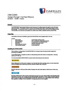
Understanding V-Memory Setup Locations The D2-CTRINT needs to have the V-memory configured in order to use the UP Counter, Mode 10. V-memory location V7633 is the most important of all the reserved memory areas because it stores the numeric value which lets the CPU know which mode has been selected. The following diagram shows the 16-bit word and the various information it stores, including the values used for the D2–CTRINT. The example shown here is for a DL230 and uses the UP counting mode. The lower bits are set to 10 for the mode, and the upper bits are set to 10 so the battery backup is enabled. Together they form the number 1010. Bits 15
14
13
Memory Location V7633 12 11 10 9 8 7 6 5
0
0
0
1
Installation and Safety Guidelines
Mode 10 UP Counter
DL230 Example
0
1
0
0
0
0
0
0
0 1
4
3
2
1
1
0
0
0
0 0
0
Miscellaneous Setup Binary Coded Decimal:
D2-CTRINT Mode Setup Binary Coded Decimal:
00 = Not Used (default) 10 = Battery Enabled (DL230/240/250–1/260) 20 = Power Up in Run (DL230 only) 30 = Selects both Battery Enable and Power Up in Run (DL230 only) 40 = Mode Change Enable in K–sequence (DL240 only) 50 = Battery Enable and Mode Change Enable in K–sequence (DL240 only)
00 = Not Used 10 = UP Counting Mode 20 = UP/DOWN Counting Mode 30 = Pulse Output Train 40 = High Speed Interrupts 50 = Pulse Catching 60 = Discrete Filtered Inputs
NOTE: It is important to look at the entire 16 bits of V7633. For simplification, zeros have been placed in bits 8 thru 15 for all ladder logic examples when loading the mode codes. There are also other V-memory locations which contain High Speed Counter Interface setup information for each I/O point. The CPU will automatically configure them with default values for the mode which has been selected.
DL205 High Speed Counter Interface Manual, 2nd Ed, Rev. A
3–5 High Speed UP Counter
Default Settings for Counter Mode 10 CW
Enable
CCW
Dummy
D2
Reset
DL230 Defaults
Up count 1 Reset
00 Not Used Reset Not Used
Nj
01
03
Dummy
DL240/250–1/260 Defaults
Note: Refer to pages 2–4 and 2–5 when wiring your particular device.
Reset
Nj External signals
02
Enable
Reset
Program signals
Reset
Nj
00
Up count 1 Reset
02
Enable
01
Dummy
03
Reset
Nj External signals
Nj
Up count 2 Reset
Program signals
Program signals
Nj External signals
The above diagram shows the physical layout of the front of the module. The actual wire connecting points on the module can be visually related to the various functions that are associated through the default configuration. There are programming examples in this chapter which show how to change some of these defaults. Default settings with V7633 set to XX10: V–Memory Location and Default Value in Module I/O Points DL230
Default Value in DL240/250–1/260
0001 (Counter Input)
0001 (Counter 1 Input)
V7635 (point 01)
0000 (Not Used)
0001 (Counter 2 Input)
V7636 (point 02)
0007 (Reset Input)
0007 (Reset Input)
V7637 (point 03)
0000 (Not Used)
0007 (Reset Input)
The values shown above have the following meaning: 1 = absolute counting mode input 7= external reset input without an interrupt While discussing memory configuration, it is good to know about the reserved memory for the presets. Below is a table with the default memory locations. CPU
Channel 1 (pt.00)
Channel 2 (pt.01)
DL230
V2320 thru V2377
Not Applicable
DL240/250–1/260
V3630 thru V3707
V3710 thru V3767
DL205 High Speed Counter Interface Manual, 2nd Ed, Rev. A
Installation and Safety Guidelines
V7634 (point 00)
3–6 High Speed UP Counter
Setting Up the CPU Configuring the V–Memory
Installation and Safety Guidelines
Mode 10 UP Counter
Step 1: Entering the Selected Mode
Each of the DL230, DL240, DL250–1 or DL260 CPUs will check V-memory to see if there is a High Speed Counter Interface Module present. The value XX10 will be read in V7633 if the module has been properly configured for UP counting. The XX represents the upper byte of V7633 value which handles such functions as enabling the backup battery and setting the PLC to start in the RUN mode. If the CPU finds that a D2–CTRINT module is present, it will check other V-memory locations to see how each point of the module has been configured. The values can be inserted into memory by using either a handheld programmer or a program edited with DirectSOFT32. There are program examples in this chapter for each counter function and mode. The following steps is a guide for configuring the V-memory for the UP counter function. The UP Counter is Mode 10 which is the value to be set into V7633. The following DirectSOFT32 diagram shows the setup procedures for communicating with your DL230, DL240, DL250–1 or DL260 CPU. Refer to DirectSOFT32 Programmers User Manual for more details.
Setting the V-Memory using RLL
Setting the V-Memory using the Memory Editor
Editing the D2–CTRINT setup at the beginning of the user program is the most common method for setting up the counter mode. Should there be a need to change any of the counter setup values after the PLC has been put in the RUN Mode, use the Memory Editor to change the values. These values will only be temporary. They should be put into the program if they are to be permanently used.
DL205 High Speed Counter Interface Manual, 2nd Ed, Rev. A
3–7 High Speed UP Counter
The following RLL example shows how to set the D2–CTRINT to Mode 10, UP Counter, in V-memory location V7633. DirectSOFT32 Display SP0
LD K10 Load Mode 10 in Accumulator Note: The upper 4 bits are not used in this case.
OUT V7633 Transfer Contents of Accumulator to V7633
Step 2: Select the Preset Mode (DL240/250– 1/260 Only)
Two commands are needed to put the values into V-memory. The value must first be loaded into the accumulator of the CPU, then the CPU must transfer the value to the memory location. In this case, 10 is to be placed in V7633. This value is loaded into the accumulator, LD K10. The CPU then writes this data to the memory location, V7633, once it reads the OUT command, OUT V7633. Notice that an SP0 contact is used in this rung. This relay is on for the first scan only. This will load the values into memory initially, thereby keeping the scan time to a minimum. If a DL230 is being used or if the Absolute counting mode is accepted for a DL240, DL250–1 or a DL260, you can skip this step. The CPU automatically assumes that the absolute presets are being used and configures the V-memory accordingly. There is only one preset mode for the DL230––Absolute. There are two different preset modes for the DL240/250–1/260,––Absolute and Incremental. The Absolute preset mode can be selected for one counter and the Incremental preset mode can be selected for the second counter, or both counters can be configured to use the same preset mode.
Installation and Safety Guidelines
DL205 High Speed Counter Interface Manual, 2nd Ed, Rev. A
3–8 High Speed UP Counter
To understand the concepts of using the Absolute and Incremental preset modes, it is essential to know some basics about the counter’s presets. Inside the PLC’s memory are twenty–four (24) preset values which can be setup for each counter. A preset is the number of pulses which are set into V–memory to be counted before an event is to be initiated. Presets are entered into successive areas of V-memory. The presets are all independent in the Absolute mode. That is, the counter compares the actual total count received from the D2–CTRINT module to a preset, when the two are equal, the event is triggered. With an Incremental preset mode, however, the presets are related to each other. In such case, the counter reaches preset A and triggers event A, then preset B is added to preset A and that becomes the number of pulses which must be counted before event B is triggered. Preset C is added to the sum of presets A and B –– that is the number of pulses required for event C to be triggered. The process of adding all the presets continues until the CPU is notified that there are no more presets to satisfy. Below is an example showing the difference between using the presets incrementally and absolutely.
Incremental F
Event C
Mode 10 UP Counter
Preset=150
F (A +B)
Event B Preset=100
Event A Preset=50
Pulse Count
Installation and Safety Guidelines
(A +B+C)
F
= Trigger point
Absolute F
Event C Preset=150
F
Event B Preset=100
F
Event A Preset=50
100 200
300 400
F 100 200
300 400
Assume that a limit switch (SW1) is being connected to one of the high speed counters. The counter is to initiate three different events at certain points in time determined by the pulse count received. Also, assume that the presets are stored (associated with each of the three events) in successive memory as 50, 100, and 150. In this example, these values are to be attended to in an incremental fashion. The counter would, in such case, trigger the 1st event when it counts 50 pulses, the 2nd event when it receives 150 pulses total (50 + 100 ) and the 3rd event when it receives 300 pulses total ( 50 + 100 + 150 ). The result would have been different if the counter had been configured to count in the Absolute mode. In such case, the counter would trigger the 1st event when it counted 50 pulses, the 2nd event when it received 100 pulses and the 3rd event when it counted 150 pulses.
DL205 High Speed Counter Interface Manual, 2nd Ed, Rev. A
3–9 High Speed UP Counter
Configuring the Preset Mode Select the Preset mode to be used by placing the proper value in memory location V7634 and/or V7635. If only one of the counters for a DL240, DL250–1 or DL260 is being used, place a counter preset value in one of these locations. The value for Absolute is 0001 and the value for Incremental is 0101. V7634 holds the value for Channel 1 (point 00), and V7635 holds the value for Channel 2 (point 01). The DL230 does not require either of these choices; because there is only one counter which is absolute. In this example, all the upper bits of V7633 are set to the default value of all zeros.
DirectSOFT32 Display SP0
LD K10
Mode 10 UP Counter
OUT V7633
LD K1
Point 00 Absolute Preset
OUT V7634
LD K101
Point 01
Incremental Preset
OUT V7635
The previous RLL example which set the D2–CTRINT to Mode 10 now has the two preset values added to it. The CPU is set for the counter to use the Absolute preset mode at point 00 and to use the Incremental preset mode at point 01. Step 3: Using Presets
The following RLL diagram loads presets into consecutive V-memory locations, starting with the default memory location V3630. Use LDD and OUTD instructions as indicated in the example below: DirectSOFT32 Display
SP0
. LDD K100 OUTD V3630
First preset for first counter Preset=100
LDD K4000 OUTD V3632 LDD K7500 OUTD V3634 LDD K12000 OUTD V3636
Second preset for first counter Preset=4000 Third preset for first counter Preset=7500 Fourth preset for first counter Preset=12000
DL205 High Speed Counter Interface Manual, 2nd Ed, Rev. A
Installation and Safety Guidelines
The final step for setting up the CPU is to configure the presets. There are up to 24 presets per counter available, also internal equal relays are embedded in the CPU so that you can use the presets for triggering events inside the RLL program.
3–10 High Speed UP Counter
Triggering Presets to Outside Events
Each of the presets are associated with special relays called equal relays. Each equal relay is assigned its corresponding preset value into two 16-bit V-memory addresses. Below is an example of how to use the equal relays. They can be referenced in relay ladder logic like a standard RLL relay. Outside events are triggered whenever the preset assigned to a particular relay is satisfied by the pulse count, the relay closes. DirectSOFT32 Display
SP570
Mode 10 UP Counter Installation and Safety Guidelines
DL205 High Speed Counter Interface Manual, 2nd Ed, Rev. A
Preset #2 met.
SP571
Preset #3 met.
SP572
Preset #4 met.
SP573
.
Preset #1 met. Y10 OUT Y11 OUT C14 OUT Y13 OUT
Equal relays used to trigger outside events. Can be used in main program or in subroutines.
3–11 High Speed UP Counter
DL240/250–1/260 Equal Relays
DL230 Equal Relays
Channel 2 (point 01)
Channel 1 (point 00)
SP540 (V3631/V3630)
SP570 (V3711/V3710)
SP540 (V2321/V2320)
SP541 (V3633/V3632)
SP571 (V3713/V3712)
SP541 (V2323/V2322)
SP542 (V3635/V3634)
SP572 (V3715/V3714)
SP542 (V2325/V2324)
SP543 (V3637/V3636)
SP573 (V3717/V3716)
SP543 (V2327/V2326)
SP544 (V3641/V3640)
SP574 (V3721/V3720)
SP544 (V2331/V2330)
SP545 (V3643/V3642)
SP575 (V3723/V3722)
SP545 (V2333/V2332)
SP546 (V3645/V3644)
SP576 (V3725/V3724)
SP546 (V2335/V2334)
SP547 (V3647/V3646)
SP577 (V3727/V3726)
SP547 (V2337/V2336)
SP550 (V3651/V3650)
SP600 (V3731/V3730)
SP550 (V2341/V2340)
SP551 (V3653/V3652)
SP601 (V3733/V3732)
SP551 (V2343/V2342)
SP552 (V3655/V3654)
SP602 (V3735/V3734)
SP552 (V2345/V2344)
SP553 (V3657/V3656)
SP603 (V3737/V3736)
SP553 (V2347/V2346)
SP554 (V3661/V3660)
SP604 (V3741/V3740)
SP554 (V2351/V2350)
SP555 (V3663/V3662)
SP605 (V3743/V3742)
SP555 (V2353/V2352)
SP556 (V3665/V3664)
SP606 (V3745/V3744)
SP556 (V2355/V2354)
SP557 (V3667/V3666)
SP607 (V3747/V3746)
SP557 (V2357/V2356)
SP560 (V3671/V3670)
SP610 (V3751/V3750)
SP560 (V2361/V2360)
SP561 (V3673/V3672)
SP611 (V3753/V3752)
SP561 (V2363/V2362)
SP562 (V3675/V3674)
SP612 (V3755/V3754)
SP562 (V2365/V2364)
SP563 (V3677/V3676)
SP613 (V3757/V3756)
SP563 (V2367/V2366)
SP564 (V3701/V3700)
SP614 (V3761/V3760)
SP564 (V2371/V2370)
SP565 (V3703/V3702)
SP615 (V3763//V3762)
SP565 (V2373/V2372)
SP566 (V3705/V3704)
SP616 (V3765/V3764)
SP566 (V2375/V2374)
SP567 (V3707/V3706)
SP617 (V3767/V3766)
SP567 (V2377/V2376)
NOTE: The consecutive addresses shown above for each relay are those assigned by the CPU as default addresses. Pointers for the start of these addresses are stored by the CPU at V7630 and V7631 for the DL240/250–1/260 and V7630 for the DL230 only. If there is a conflict of addresses because of pre-existing code written to these addresses, change the default block of addresses by placing a different pointer value in V7630 or V7631 in the relay ladder logic, depending on the CPU and preference. For example, to change the starting address for the relays belonging to Channel 1 to V2500, change the program to write an octal 2500 to V7630. The results are that the CPU will reserve 48 consecutive 16-bit memory addresses (32 bits per preset for the 24 presets available) for SP540 to SP567 equal relays.
DL205 High Speed Counter Interface Manual, 2nd Ed, Rev. A
Installation and Safety Guidelines
Channel 1 (point 00)
3–12 High Speed UP Counter
Custom Configurations There may be a time when the factory defaults will not satisfy an application. In this case the defaults can be changed so the D2–CTRINT can work for almost any application. The following tables are provided with the values needed for custom configurations. DL230 Custom Configuration
Mode 10 Options for the DL230 Point Number V-Memory Definition Location
Hex Value
point 00
V7634
UP Counter #1 (default)
0001 (absolute) default
point 01
V7635
Not Used (default)
0000 default
Discrete Input
xx06 *
Reset UP Counter (default)
0007 (no interrupt) default
point 02
V7636
0107 (interrupt)
Mode 10 UP Counter
point 03
point 04
V7637
Not Used
Discrete Input
xx06 *
Not Used (default)
0000 default
Discrete Input
xx06 *
Pulse Output (CCW)
Not Used
Note: The lower byte of V7633 is set to 10. * xx = filter time. Filter time range = 0 to 99ms.
Installation and Safety Guidelines
For the filtered inputs, the xx signifies the filter time in milliseconds, i.e. 1006 is a 10ms filter. For the DL230, either place zeros (0) in V7635, V7636 and V7637 or enter the proper hex value for the discrete input point. The DL240/250–1/260 has more options to chose for custom configuring. The chart on the next page shows you those options.
DL205 High Speed Counter Interface Manual, 2nd Ed, Rev. A
3–13 High Speed UP Counter
DL240/250–1/260 Custom Configuration
Point Number point 00
V-Memory Location V7634
Definition
Hex Value
UP Counter #1
0001 (absolute) default 0101 (incremental)
point 01
V7635
UP Counter #2
0001 (absolute) default 0101 (incremental)
point 02
V7636
Pulse Catcher
0005
Discrete Input
xx06 *
Reset UP Counter #1 0007** (no interrupt) default no Z pulse or index marker recognition 0107 (interrupt) can recognize Z pulse or index marker 0207 (interrupt) no Z pulse or index marker recognition
0307 uses Z pulse recognition in the interrupt
point 03
V7637
Pulse Catch
0005
Discrete Input
xx06 *
Reset UP Counter #2 0007** (no interrupt) default no Z pulse or index marker recognition 0107 (interrupt) can recognize Z pulse or index marker
0207 (interrupt) no Z pulse or index marker recognition
point 04 (Mode 30) Not Used
Pulse Catch
0005
Discrete Input
xx06 *
Pulse Output (CCW)
Not Used
Note: The lower byte of V7633 is set to 10. * xx = filter time. Filter time range = 0 to 99ms. ** In a high speed application using a high resolution encoder, with the CPU programmed with presets that span the resolution of the encoder, you may lose pulses in the higher range of presets.
When using constants K7 or K107 in V7636 or V7637, the counter module will read the preset V–memory each time the counter is reset or at the index marker location. When using K207 or K307, the counter module reads the preset V–memory only at power up, or when a CPU mode change occurs (i.e. PROGRAM to RUN transition). NOTE: If presets are written to V-memory for the D2–CTRINT module during program execution the counter may not be able to run at high speed, high resolution applications, since reading these locations during a reset may result in lost pulses.
DL205 High Speed Counter Interface Manual, 2nd Ed, Rev. A
Installation and Safety Guidelines
0307 uses Z pulse recognition in the interrupt
3–14 High Speed UP Counter
Writing the Control Program The control program is ready to be written after the High Speed UP Counter parameters have been configured. Writing the RLL program for the High Speed Counter is much the same as for a regular counter. The embedded high speed counters which are activated through the D2–CTRINT module, have three inputs. The first input is to enable the counter, the second one is a dummy and the third is to reset the counter. The dummy has no function other than it is required by DirectSOFT32. The three inputs are required for DirectSOFT32 to accept the program.
DirectSOFT32 Required
ENI
Enable Input Dummy Input
UDC
CT76
K17688
Mode 10 UP Counter
Reset Input
Installation and Safety Guidelines
Must be: CT76 for a DL230 CT174 for point 01 or CT176 for point 02 for the DL240/250-1/260 Preset Range: 1-99,999,999
The mnemonic for the counter is UDC. It is found in the DirectSOFT32 instruction browser that pulls down using the F7 hotkey while in the Edit Mode. After selecting the UDC, a box appears asking for the counter address and preset value. The counter address in the above example is CT76. This is the address which must be used for the DL230 CPU. The preset value of 17688 has been used in the example. This is the number of pulses to be received and counted before the output of the counter goes high. Any value between 1 and 99,999,999 can be programmed. The DL240/250–1/260 CPUs require addresses of CT174 for Channel 1 (point 00) and CT176 for Channel 2 (point 01). If a different address is used, the CPU will think that a standard, non-high speed, counter has been programmed, and the D2–CTRINT will not be enabled. After entering the counter address and preset, enter the contact addresses for the contacts which are automatically drawn in the RLL program. High Speed Counter data CPU Counter No. for Channel 1 (pt 00)
Counter No. for Channel 2 (pt 01)
Preset Limits
DL230
76
N/A
1–99,999,999
DL240/250–1/260
174
176
1–99,999,999
DL205 High Speed Counter Interface Manual, 2nd Ed, Rev. A
3–15 High Speed UP Counter
Example 1: UP Counters Without Presets The following example uses either a DL240, a DL250–1 or a DL260 CPU. The example also uses both UP counters at points 00 and 01, and the resets at points 02 and 03. The counter attached to point 00 is to trigger a jump to an interrupt subroutine when it is externally reset by point 02. There is no interrupt subroutine written for the reset for point 03. The second counter resets after receiving 20,456 pulses. SP0 ENI
Enables Interrupts
SP0 LD K0010
DirectSOFT32 Display
OUT V7633
Select UP Counter Mode 10
LD K1 OUT V7634
Absolute mode (point 00)
OUT V7635
Absolute mode (point 01)
LD K107 OUT V7636
External Reset w/Interrupt (point 02) (Custom)
LD K7 OUT V7637 SP1 SP1
External Reset wo/Interrupt (point 03) (Default)
UDC CT174 K18724
SP1
First Counter for point 00 (External Reset at point 02)
SP1 SP1
UDC CT176
Second Counter for point 01 (Self-Resetting or External Reset at Point 03.)
END
Interrupt Subroutine
INT O0 C6 C7 X2
Y10 OUT Y11 OUT Y20–Y27 RSTI IRT
The outputs in this subroutine illustrate that the events do not have to be tied to the equal relays. When the external reset at point 02 (X2) for Counter #1 goes high, the counter is reset to zero(0) and Y20 through Y27 are reset immediately.
Notice the counters have been properly labeled CT174 and CT176. The presets have been set to the respective numbers specified. The load accumulator instructions have setup the V-memory as required, i.e. 10 in V7633 for the mode, 1 in V7634 and V7635 for absolute mode and 0107 in V7636 to trigger a jump to an interrupt subroutine. Also in the setup is the reset of the counter CT174 when point 02 goes high and 0007 in V7637 to indicate no jump to an interrupt subroutine when CT176 is externally reset.
DL205 High Speed Counter Interface Manual, 2nd Ed, Rev. A
Installation and Safety Guidelines
K20456 CT176
3–16
Mode 10 UP Counter
High Speed UP Counter
Reset with an Interrupt In the previous example, whenever point 02 is enabled, CT174 is reset to zero (0). At the same time, the CPU suspends its normal main program scan and execution, going to the interrupt subroutine. When it finishes executing the subroutine and encounters the return statement, the execution returns to the exact point in the main program where it left off. Notice the interrupt subroutine must be labeled to match the input point to which its corresponding counter is wired, i.e. 00 is used. Interrupt Operation in Ladder Logic The programmer should be aware of the sequence of events during an interrupt in order to avoid unexpected I/O operations. When an interrupt occurs, the CPU halts execution of the current instruction. It then executes the interrupt program, then returns to complete the suspended instruction. If the suspended instruction involves the same memory byte as an operation in the interrupt program, the CPU may not retain the correct status of that byte. This is because I/O status is updated one byte at a time. EXAMPLE: An interrupt occurs during execution of the “OUT Y17” instructin, which has read the current status of the I/O byte which contains Y17. The interrupt program in this example sets Y10, a bit which is in the same byte as Y17. When control returns to the suspended instruction, it uses the status it read from the I/O status table before the interrupt to complete its operation. It turns Y17 ON, but still has the old value for Y10 (OFF). When the byte is written to the I/O status table, the CPU has lost the result of the interrupt operation. To avoid this problem, the programmer should use control relays (C memory) in bytes unused elsewhere for SET or OUT operations in the interrupt programs. I/O Status 17 Y10 0 0 0 0 0 0 0 0
Main Program
Interrupt Program
Execution of OUT Y17
Installation and Safety Guidelines
Installation and Safety Guidelines
Status Read
0 0 0 0 0 0 0 0 Store 8 bit status data
INT0 occurs Interrupt Program for INT0
17 Y10 0 0 0 0 0 0 0 0
Status Read
Execution of SET Y10
0 0 0 0 0 0 0 0 17 Y10 0 0 0 0 0 0 0 1 Y10 turns ON
Status Overwrite
Continues Execution of OUT Y17 Status Overwrite
1 0 0 0 0 0 0 0
17 Y10 1 0 0 0 0 0 0 0 Y10 turns OFF
DL205 High Speed Counter Interface Manual, 2nd Ed, Rev. A
Bit 7 turns on
0 0 0 0 0 0 0 1
3–17 High Speed UP Counter
Example 2: UP Counters with Multiple Presets The next DL240/250–1/260 example will use some features from other modes with multiple presets for a single counter. The example will use only one counter for point 00 configuring the preset mode as absolute and having a reset with an interrupt at point 02. Point 01 will be made a pulse catcher and point 03 will be used as a discrete filtered input. Referring to page 3–13 the V–memory locations for control points 01 and 03 are V7635 and V7637 respectively. This is true for any mode or mix that is used. Place 0005 in V7635 for the pulse catch input, and xx06 in V7637 for the filtered discrete input. This example will use 10 ms for the filtered time constant. The value to put in V7637 is 1006. The relay ladder logic to accomplish this is on the next page. This example also uses multiple presets of 5000, 10000 and 15000 for the counter. Memory Locations for Multiple Presets Counter No. Memory Range/Default Preset Addresses Equal Relays 76 (DL230)
V2320 to V2377
SP540–SP567
174 (DL240/250–1/260)
V3630 to V3707
SP540–SP567
176 (DL240/250–1/260)
V3710 to V3767
SP570–SP617
NOTE: The above table indicates the default V-memory locations for setting the presets and the corresponding special equal relays assigned to each. Be aware that the default addresses can be changed to begin elsewhere merely by changing the pointers at V7630 (Channel 1) and V7631 (Channel 2) to the octal value of the new addresses.
NOTE: When using two counters with the SP570 contacts,etc., INT01 must be used.
DL205 High Speed Counter Interface Manual, 2nd Ed, Rev. A
Installation and Safety Guidelines
Each preset requires two V-memory locations (32–bits), i.e. V2320 and V2321 are the first preset, V2322 and V2323 are the second, etc. Each of these presets has a special equal relay assigned to it. The numbering assignment for these are one digit apart, i.e. SP540 assigned to the first preset, SP541 assigned to the second preset, etc. So that the CPU knows that it has seen all the presets when in the Absolute mode, place an FFFF in the next available V-memory preset location following the final preset (if not using all 24 presets available). In the Incremental mode, place FFFF as in the Absolute mode or place FF00 in the last preset location to reset the counter, set the accumulated pulse count to zero (0) and continue counting. In the example, this has been placed in V3636 since the last preset was in V3634 and only using three presets. Place 00FF in the last preset location to reset the counter and not reset the accumulated pulse count.
3–18 High Speed UP Counter
DirectSOFT32 Display
SP0
DL240/250–1/ 260 Example
SP0
ENI LD
Enables Interrupt, to use Special Relays
K10 OUT V7633
Mode 10
LD K1 OUT V7634
Absolute mode at point 00
LD K5 OUT V7635 LD K107 OUT V7636 LD K1006 OUT V7637
Pulse Catcher at point 01
External Reset w/Interrupt (point 02––X2) Discrete 10 ms Filtered Input (point 03)
LDD K5000
Mode 10 UP Counter
OUTD V3630 LDD K10000 OUTD V3632
Additional Presets for Counter of 5000, 10000 and 15000
LDD K15000 OUTD V3634
Installation and Safety Guidelines
LDD KFFFF OUTD V3636
Tell CPU that there are no more presets.
SP1 SP1
UDC CT174 K18724
Counter for point 00
SP1
END INT O0 SP540 SP541 SP542 X2
Y20 SET I Y21 SET I Y22 SET I Y20–Y27 RSTI IRT
Interrupt Subroutine Subroutine will be executed when the Preset equals the Current Count and the Reset is triggered.
NOTE: To trigger outside events with the three presets, assign SP540,541 and 542 respectively to V3630, V3632, and V3634. (See Table on Page 3-11.
DL205 High Speed Counter Interface Manual, 2nd Ed, Rev. A
3–19 High Speed UP Counter
Example 3: Speed Control for an AC Motor The next example will use one UP counter for a DL240, DL250–1 or DL260 to control the timing for a small AC motor inverter. Unlike the positioning applications discussed later in Chapter 5 for the pulse train function (Mode 30) where the interface module does all the ramping and speed control of a stepper motor, this application will rely on a separate motor drive to provide all of the intelligence for proper acceleration/deceleration ramping and motor speed control for an AC induction type motor. Velocity High Medium Low
100
Pulse Count (Time)
4000
10000
17000
Y10 Y11 Y12
Assume that there are input and output modules in a DL205 base and that X10 and X11 of the input module are wired to a START/STOP switch. The inverter being used in this example has programmable input relays that accept low, medium and high speed ranges that have been programmed into the drive. The drive automatically powers up at the low speed setting. Low, medium and high speed input relays are wired to Y10, Y11 and Y12 respectively. The goal here is to write the appropriate relay logic to accomplish the above start and stop of the drive to match the curve shown above. Input Output D2ĆCTRINT Module Module
00
X10 X11
Y10 Y11 Y12
3-Speed Drive
Low Medium High
AC Motor Start Stop
Encoder
DL205 High Speed Counter Interface Manual, 2nd Ed, Rev. A
Installation and Safety Guidelines
Speeds
3–20 High Speed UP Counter
Example Program DirectSOFT32 Display SP0 ENI
SP0
LD K10 OUT V7633
Select UP Counter Mode 10
LD K1 OUT V7634
Absolute mode at point 00
LDD K100 OUTD V3630 LDD K4000 OUTD V3632 LDD K10000
Presets of 100, 4000, 10000, and 17000.
Mode 10 UP Counter
OUTD V3634 LDD K17000 OUTD V3636 LDD KFFFF
Installation and Safety Guidelines
OUTD V3640
Tell CPU there are no more presets.
SP1 SP1
UDC CT174
Counter for point 00
K20000 X11 X10 C10 X11
C10 PD Y10 SET Y10–Y12 RST END
INT O0 SP540 SP541 SP542 SP543
Y11 SET I Y12 SET I Y12 RST I Y10 Y11 RST I IRT
DL205 High Speed Counter Interface Manual, 2nd Ed, Rev. A
100 pulses 4000 pulses 10000 pulses 17000 pulses
Interrupt Subroutine
3–21 High Speed UP Counter
Explanation of RLL The following describes the events as they are scanned and executed in the example program on the preceding page. 1. The START button, which is connected to X10, is pressed. Y10 latches ON and the inverter starts ramping to low speed. 2. When the D2-CTRINT counts 100 pulses, which is the first preset (100), SP540 goes HIGH and latches Y11 ON. This switches the inverter to medium speed mode. 3. When the D2-CTRINT counts 4000 pulses, the second preset, SP541 goes HIGH and latches Y12 ON. This switches the inverter to the high speed mode. 4. When the D2-CTRINT counts 10000, SP542 goes HIGH and unlatches (resets) Y12 OFF. This switches the inverter back into the medium speed mode. 5. When 17000 pulses are counted, the fourth preset, SP543 goes HIGH and resets outputs (Y10, Y11) OFF. This turns the inverter OFF.
Installation and Safety Guidelines
DL205 High Speed Counter Interface Manual, 2nd Ed, Rev. A
3–22 High Speed UP Counter
Example 4: Counting Pulses at a High Frequency Where Accuracy is Critical In this example, wire being drawn from a spool is constantly being labeled and cut to length. The process requires continuous unwinding of the wire for cutting. An encoder is connected to a roller shaft and is producing pulses at a high frequency which are used to determine the length of the wire for cutting. A reset of the counter at these high frequencies would cause a loss of pulses (depending on CPU scan time) and result in some wire lengths to be inaccurate. To avoid this problem, a program can be written that resets the counter immediately at the proper preset (to be determined) with no loss of pulses. DirectSOFT32 Display SP0 ENI SP0
Enables Use of Interrupts
LD K10 OUT V7633
Mode 10
LD K101
Mode 10 UP Counter
OUT V7634 LD K101 OUT V7635
Incremental preset mode at point 00 (first counter) Incremental preset mode at point 01 (second counter)
LD K7 OUT V7636
External reset without interrupt for first counter.
LD K7
Installation and Safety Guidelines
OUT V7637 SP0
LDD K1
External reset without interrupt for second counter. First preset for first counter
OUTD V3630 LDD K499 OUTD V3632 LDD K7500
Second preset for first counter
Third preset for first counter
OUTD V3634 LDD K12000
Fourth preset for first counter
OUTD V3636 LDD KFF00 OUTD V3640
Continued on next page
DL205 High Speed Counter Interface Manual, 2nd Ed, Rev. A
Reset the first counter
3–23 High Speed UP Counter
DirectSOFT32 Display
SP1 SP1
UDC CT174
First Counter
K99999 SP1
Second Counter not being used.
END
INT O0
SP540
SP541
Interrupt Subroutine Wire Cutter Y20 SET I Wire Cutter Y20 RSTI Gauge Labeler Y21 SET I External Counter Y23 SETI
SP542
Turn Off the Wire Cutter Turn On Gauge Labeler Increment External Counter (User Supplied)
Turn Off Gauge Labeler
Part No. Labeler Y22 SET I
Turn On Part No. Labeler
Part No. Labeler Y22 RST I
Turn Off Part No. Labeler
External Counter Y23 RSTI IRT
Increment External Counter Return from Interrupt Subroutine to main program
Equal Relays SP540, SP541, SP542 and SP543 turn ON when their respective presets are reached. They are Incremental and not Absolute; each preset is added to the previous preset. For example SP542 goes ON when (1+499+7500) or 8000 total pulses have been reached. Note the use of SETI and RSTI instructions inside the interrupt routine.
DL205 High Speed Counter Interface Manual, 2nd Ed, Rev. A
Installation and Safety Guidelines
SP543
Gauge Labeler Y21 RSTI
Turn On Wire Cutter and Cut
3–24 High Speed UP Counter
Troubleshooting
Installation and Safety Guidelines
Mode 10 UP Counter
Things to check
Counter Doesn’t Count
No Input Signal
The following information may provide some assistance in dealing with problems which may be encountered when setting up the D2–CTRINT module, should they occur. Experience has shown that most problems occur because of improper configuration. Always re-check the CPU setup before anything else. For verifying types of inputs (or outputs) besides those related to UP counting, see the Chapters in this manual covering the specific function. Listed below are some things that could possibly go wrong with the UP counter inputs: 1. The UP counter is not counting when the encoder or other device is making low to high transitions. 2. The status indicator LED is not lighting for the input point where the UP counter is wired (i.e. points 00 and 01). 3. The counter does not appear to be counting synchronously with the input device’s transitional states. 4. The counter is not resetting itself after reaching the preset. 5. The counter is not jumping to the subroutine as expected when the preset is reached. 6. The counter is counting properly and executing the interrupt properly, but it does not continue counting after the interrupt subroutine has been completed. The actual count should be in view when monitoring the counter with DirectSOFT32. If this is not happening: 1. The software configuration may be incorrect. Re-check the setup. 2. The field device may be defective. 3. The field device may be O.K., but it is too fast for the counter. 4. The wiring may be defective. 5. The input voltage may not be within specification. 6. The D2–CTRINT module is defective. Verify that there is a signal present at point 01 or 02. Check the encoder, or input device, which is connected to the module. Instrumentation can be used to check the outputs; either an oscilloscope or a logic test probe. If the logic test probe is used, it should be the type that has the option to select either TTL or CMOS settings, it should also be able to switch it to the pulse train mode. The peak signal level being output from points 03 and 04 is 5-volts with 15% tolerance. If the signals cannot be read with the TTL setting, use the CMOS setting. The probe may not be able to read the TTL because of the 15% tolerance specification.
DL205 High Speed Counter Interface Manual, 2nd Ed, Rev. A
3–25 High Speed UP Counter
Touch probe to counter input points 01 and 02. Field device must be wired so that pulses are being sent.
Typical Low Cost Logic Probe (Not available from AutomationDirect) High Signal Indicator Low Signal Indicator Pulse Train Indicator Normal/Pulse Train Switch TTL/CMOS Switch
Connect power leads to your recommended power supply––not PLC power supply.
DL205 High Speed Counter Interface Manual, 2nd Ed, Rev. A
Installation and Safety Guidelines
A rotary encoder may also not be operating properly because of a poor coupling between the encoder and the motor shaft. Check to be certain that the coupling is not defective. Check the specifications of the field device. Make sure that the output signal matches up the specifications of the D2–CTRINT module. Too fast – The pulse rate cannot exceed 5 kHz. If this is suspect, try to slow down the pulse rate to see if the problem is solved. The pulse width may also be too narrow. The pulse must remain high for at least 100ms in order for the module to detect it. Wiring - Simple as this might seem, quite often poor wiring is the cause of many problems. Make sure that there is a complete electrical loop between the device and the input module. Along with visual inspection, use a voltmeter to check this. Input Voltage - If the input device is producing a signal which is less than 12 volts, the counter will either not function properly or function improperly. Use a field device with the proper signal level if necessary. Improper Configuration - The module may be looking for a counter which doesn’t exist. Check the RLL program and be sure that the counter is addressed properly. Be certain that the inputs to the counter are properly configured. Is the counter enabled? If using a DL230, only one High Speed Counter can be used.
3–26 High Speed UP Counter
LED’s Do Not Light Make sure the PWR or BAT LED’s are not lit on the CPU module. If either the battery power or the external power indicators are not illuminated, there is either a defective power supply, the batteries are worn out or there is no power to the PLC. Check and be sure that the status indicators are blinking as pulse signals are received at the proper input point on the module (i.e. 0 or 1). Check the field device to make sure it is operating. Use an oscilloscope or digital counter to verify the presence of a pulse train at the input point(s) or use the Change Value feature in DirectSOFT32 to force the input point ON. Refer to the DirectSOFT32 Software Programmers Manual to use this feature. If after forcing the signal ON, and the appropriate LED does not light, the module is defective.
Non–Synchronous If the counter is suspect of counting faster than the field device is sending pulses, then the interface may be experiencing noise. Try connecting a shielded wire Pulsing between the field device and the module input. The wire should be shielded at one end only-- normally the encoder side. If the PLC is interfaced to a rotary shaft encoder, a loose coupling could also be causing the problem. Check the coupling. If a reset is not present when expected, check the configuration. Is the proper value No Reset for a reset being used? Is the module looking for an external reset? If so, is the field device supplying the reset signal (which should be connected to either points 02 or 03) operating properly. Manually operate the reset device. Not Jumping to Is the interrupt subroutine labeled properly? The interrupt subroutine must have the same number as the I/O point to which the counter is connected. Is there supposed Interrupt to be an external interrupt, but the external device is not sending the signal? Does the external interrupt device meet the input criteria? Check all of these possibilities. Not Returning from Does the interrupt subroutine end with an Interrupt Return instruction in the RLL program? Is there an endless loop inside the subroutine? Is there a conditional Interrupt return and the condition has not been met?
Installation and Safety Guidelines
Mode 10 UP Counter
WARNING: Take all necessary precautions to protect personnel and equipment when forcing inputs and outputs, since the equipment on the output side of the system may be energized.
DL205 High Speed Counter Interface Manual, 2nd Ed, Rev. A
Mode 20 – High Speed UP/DOWN Counter In This Chapter. . . .
14
Ċ Wiring the UP/DOWN Counter Ċ Configuring the UP/DOWN Counter Parameters Ċ Writing the Control Program Ċ Verification of Proper Operation Ċ Troubleshooting
4–2 High Speed UP/DOWN Counter
Using the UP/DOWN Counter, Mode 20 (DL240/250–1/260 Only) It is recommended that you read Chapter 1, Getting Started, which introduces the six different modes of operation of the D2–CTRINT module, before selecting a mode. Even though several features can be mixed from several modes, you must select one of the modes as your primary mode. Mode 20, UP/DOWN Counter will be the only mode discussed in this chapter. It is also important to read Chapter 2, concerning the general guidelines for field wiring your device to the module. You may want to refer to Chapter 2 as you learn more about the D2–CTRINT’s UP/DOWN counting function. DL240/250–1/260 UP/DOWN Counter Mode 20 D2–CTRINT Terminals UP Counting CW CCW
Proximity Sensor
C0
DOWN Counting
C1 C2
Reset
D2
Choose from either configuration
Mode 20: UP/DOWN Counter
Mode 20 UP/DOWN Counter
Proximity Sensor
Phase A
C0
Phase B
C1
Encoder
C2
Reset
To Terminal 02 01 00 Enable Dummy Reset
Nj Nj
Input A Input B Ext. Reset
Program signals connect to ground
The above diagram and illustration shows points C0 and C1 which are the two primary UP/DOWN counter connecting points for the pulse input devices. Point C2 is the reset input. The counter can be reset either through the operating program using relay ladder logic or they can be reset by an external field device. Points 00 through 03 are the respective common connections for the counter inputs and optional external reset. Point 04 and C4 are for pulse output signals and are not used in this mode.
DL205 High Speed Counter Interface Manual, 2nd Ed, Rev. A
4–3 High Sped UP/DOWN Counter
UP/DOWN Counting Overview Encoders In General
00 01
Encoder Reset
Drill Moving to Right Drill Moving to Left
02
Encoder
DL205 High Speed Counter Interface Manual, 2nd Ed, Rev. A
Mode 20: UP/DOWN Counter
UP Count DOWN Count
Mode 20 UP/DOWN Counters
Standard UP/DOWN Counting
Encoders are used in all types of applications, including machine tooling, semiconductor positioning and multi–axis positioning. In the most general sense, the encoder puts out a certain number of pulses for each revolution of the shaft. Encoders can be easily interfaced to the D2–CTRINT module for accurate position monitoring and control. There are two types of encoders available, incremental and absolute. These encoders have a rotating shaft which are normally coupled (mechanically) to motors for machine control. The incremental encoder has a pulse output which corresponds to the rotation of the shaft. This pulse output is the encoder resolution corresponding to the number of pulses per revolution. There are two outputs from an incremental encoder, A and B. There is also an output for home position. The encoder outputs can be used for either counting or for direction control (quadrature). The absolute encoder is used for more precise positioning. The output from the absolute encoder is a binary value relating to degrees per revolution (360/revolution). Both types of encoders, incremental and absolute, are available from AutomationDirect. More information about the encoders is available from both our website and catalog. There are two basic ways to use the UP/DOWN counter, either for standard UP/DOWN counting from two separate sources (i.e. single pulse from two encoders) or for quadrature UP/DOWN counting using encoder outputs A and B. The first way, using the D2–CTRINT module as a standard UP/DOWN counter, is commonly used for position control. For example, a drill head may need to be moved in a certain direction horizontally. At the same time, the drill head position may also need to be tracked. This can be done by counting pulses received from two encoders. When the drill moves in one direction, an encoder will increment an accumulated count (UP count). When the drill moves in the opposite direction, a second encoder will decrement the accumulated count (DOWN count). The drill position will be known by looking at the accumulated count at any given time. Using the high speed positioning example, point 00 would receive signals from an encoder that keeps track of movement in one direction, to the right. Point 01 would keep track of movement to the left via a second encoder. Incrementing and decrementing the UP/DOWN counter can happen simultaneously or during separate intervals of time. Drill Positioning Example
4–4 High Speed UP/DOWN Counter
Quadrature UP/DOWN Counting
The second way to use the D2–CTRINT is to keep track of the direction which a motor is turning. This is accomplished by using a quadrature encoder with the A and B outputs connected to the UP/DOWN counter. The A and B pulse trains which are processed have a 90 degree phase difference. This means that one pulse train leads the other pulse train by 90 degrees. From this information, the D2–CTRINT can be configured to know if the shaft is turning clockwise or counterclockwise. The diagram below, shows both standard UP/DOWN counting and the quadrature UP/DOWN counting being performed with encoders. The encoders shown for the standard UP/DOWN counting could be replaced with photoelectric sensors, or even limit switches. Quadrature counting, on the other hand, is confined specifically to shaft encoders. UP Count
00
DOWN Count
01
Encoder Reset
02
Choose from either configuration Encoder
Mode 20 UP/DOWN Counter
Phase A Phase B
Mode 20: UP/DOWN Counter
2–Channel Encoder
DL205 High Speed Counter Interface Manual, 2nd Ed, Rev. A
00 01
Reset
02
4–5 High Sped UP/DOWN Counter
How a Quadrature Encoder Works
As mentioned previously, a quadrature encoder has two outputs, A and B. These outputs can be used to sense position and direction of a motor driven device. This is possible because of the quadrature outputs, A and B, are 90° out of phase to each other as shown in the figure below: Leading Edge Signal
Output A
Output B
90° out of phase
Mode 20 UP/DOWN Counters
Like any quadrature encoder, four unique logic states are created internal to the encoder. This is based on the rising edge to rising edge (one cycle) on output A or B. The rising edge of Output A, the rising edge of Output B, the falling edge of Output A and the falling edge of Output B form the complete quadrature. In the example above, Output A is the leading signal, and it will cause the counter to count up. This would indicate to the CPU that the motor shaft is turning clockwise. However, suppose instead that the signals looked like the diagram below:
Output A
Mode 20: UP/DOWN Counter
Leading Edge Signal Output B
90° out of phase
Now Output B is the leading signal, and it will cause the counter to count down. This would indicate to the CPU that the motor shaft is turning counter-clockwise.
DL205 High Speed Counter Interface Manual, 2nd Ed, Rev. A
4–6 High Speed UP/DOWN Counter
Understanding V-Memory Setup Locations V-memory location V7633 is the most important of all the reserved memory areas because it stores the numeric value which lets the CPU know which mode has been selected. The following diagram shows the 16-bit word and the various information it stores––including the values used for the Counter Interface Module. The example shown here uses the UP/DOWN counting mode. The lower bits are set to 20 and the upper bits are set to 10 so the battery backup is enabled. Together they form the number 1020. Bits 15
14
13
Memory Location V7633 12 11 10 9 8 7 6 5
0
0
0
1
0
Mode 20: UP/DOWN Counter
Mode 20 UP/DOWN Counter
1
0
0
0
0
0
0
Miscellaneous Setup Binary Coded Decimal: 00 = Not Used (default) 10 = Battery Enabled (DL230/240/250–1/260) 20 = Power Up in Run (DL230 only) 30 = Selects both Battery Enable and Power Up in Run (DL230 only) 40 = Mode Change Enable in K–sequence (DL240 only) 50 = Battery Enable and Mode Change Enable in K–sequence (DL240 only)
1 2
4
3
2
1
0
0
0
0
0 0
0
D2-CTRINT Mode Setup Binary Coded Decimal: 00 = Not Used 10 = UP Counting Mode 20 = UP/DOWN Counting Mode 30 = Pulse Output Train 40 = High Speed Interrupts 50 = Pulse Catching 60 = Discrete Filtered Inputs
NOTE: It is important to look at the entire 16 bits at V7633. If the RLL program only sets the bits in the lower byte when entering the mode value, the upper bits will be overwritten with zeros (0’s). Always enter a 4-digit BCD value when writing to V-memory. This way, the proper value will be written into the upper bits. There are also other V-memory locations which contain High Speed Counter Interface Module setup information for each I/O point. The CPU will automatically configure them with default values for the mode which has been selected.
DL205 High Speed Counter Interface Manual, 2nd Ed, Rev. A
4–7 High Sped UP/DOWN Counter
DL240/250–1/260 Quadrature Counter Configuration D2–CTRINT Terminals
CW CCW
Choose either configuration
D2
Phase A
00
Phase B
2–Channel Encoder
01 02
Reset
To Terminal 02 01 00 Enable Dummy Reset
Nj Nj
Input A Input B Ext. Reset
Program signals External signals
Note: Refer to pages 2–4 and 2–5 when wiring your particular device.
0002
UP/DWN Input
V7635 (point 01)
0000
Not Used
V7636 (point 02)
0007
Reset
V7637 (point 03)
1006
Discrete Input
The values shown above have the following meaning: 0002 =UP/DOWN quadrature, Absolute counter mode 0007 = External reset input without an interrupt 1006 = Discrete input with 10 ms filter While discussing memory configuration, it is important to mention the reserved memory for the presets. The default memory locations are shown below. CPU
Channel 1 (pt.00) & (pt.01)
DL240/250–1/260
V3630 thru V3707
DL205 High Speed Counter Interface Manual, 2nd Ed, Rev. A
Mode 20: UP/DOWN Counter
V7634 (point 00)
Mode 20 UP/DOWN Counters
The diagram above shows the physical layout of the front of the module. The actual wire connecting points on the module can be visually related to the various functions that are associated through the default counter configuration. There are programming examples in this chapter which show how to change some of these defaults. Default settings with V7633 set to XX20: V–Memory Location and Default Value in Description I/O points on the module DL240/250–1/260
4–8 High Speed UP/DOWN Counter
Setting Up the CPU Configuring the V–Memory
Mode 20: UP/DOWN Counter
Mode 20 UP/DOWN Counter
Step 1: Entering the Mode Selected
The DL240/250–1/260 CPUs check the V-memory to see if there is a High Speed Counter Interface Module present. There will be a hexadecimal number 10, 20, 30, 40, 50 or 60 in V7633 if a module has been properly configured. This is the value which is entered in the RLL program setup. If the CPU finds that a Counter Interface Module is present, other V-memory locations will be checked to see how each point of the module has been configured. The values can be entered into memory by using either a handheld programmer or by editing them into a control program using DirectSOFT32. The following examples will show how to use DirectSOFT32 to configure the UP/DOWN Counter. The UP/DOWN Counter is Mode 20 which is the value to be set into V7633. The following DirectSOFT32 diagram shows the setup procedures for communicating with your DL240/250–1/260 PLC. Refer to the DirectSOFT32 Programmers User Manual for more details.
Setting the V-Memory using RLL
Setting the V-Memory using the Memory Editor
Editing the D2–CTRINT setup at the beginning of the user program is the most efficient method for setting up the counter mode. Should there be a need to change any of the counter setup values after the PLC has been put in the RUN Mode, use the Memory Editor to change the values. These values will only be temporary. They should be put into the program if they are to be used permanently.
DL205 High Speed Counter Interface Manual, 2nd Ed, Rev. A
4–9 High Sped UP/DOWN Counter
The following RLL example shows how to set the UP/DOWN Counter, Mode 20, in V-memory location V7633. DirectSOFT32 Display SP0
LD K0020 Load Mode 20 in Accumulator. The upper 4 bits are not being used.
OUT V7633 Transfer Contents of Accumulator to V7633
Mode 20: UP/DOWN Counter
DL205 High Speed Counter Interface Manual, 2nd Ed, Rev. A
Mode 20 UP/DOWN Counters
Step 2: Select the Preset Mode
Two commands are needed to put the values into V-memory. The value must first be loaded into the accumulator of the CPU, then the CPU must transfer the value to the memory location. In this case, 20 is to be placed in V7633. This value is loaded into the accumulator, LD K20. The CPU then writes this data to the memory location, V7633, once it reads the OUT command, OUT V7633. Notice that an SP0 contact is used in this rung. This relay is on for the first scan only. Thus, it will load the values in memory initially, thereby keeping the scan time to a minimum There are two different preset modes to chose from––either Absolute or Incremental. If the default Absolute mode of presets has been accepted, skip this step and go on to Step 3. To understand the concepts of using the Absolute and Incremental preset modes, it is essential to know some basics about the counter’s presets. Inside the PLC’s memory up to twenty–four (24) preset values can be setup for each counter. A preset is the number of pulses which are chosen to be counted before an event is to be initiated. Presets are entered into successive areas of V-memory. With the Absolute mode, the presets are all independent. That is, the counter compares the actual total count received from the D2–CTRINT module to a preset, when the two are equal, the event is triggered. With an Incremental preset mode, however, the presets are related to each other. In such case, the counter reaches preset A and triggers event A, then preset B is added to preset A and that becomes the number of pulses that must be counted before event B is triggered. Preset C is added to the sum of presets A and B and that is the number of pulses required for event C to be triggered. The process of adding all the presets continues until the CPU is notified that there are no more presets to satisfy.
4–10 High Speed UP/DOWN Counter
Below is an example showing the difference between using the presets Incrementally and Absolutely.
Incremental F
Event C Preset=150
(A +B+C)
F (A +B)
Event B Preset=100
Preset=50
Mode 20 UP/DOWN Counter
Pulse Count
Absolute
= Trigger point
F
Event C Preset=150
F
Event B Preset=100
F
Event A
Mode 20: UP/DOWN Counter
F
Event A Preset=50
100 200
300 400
F 100 200
300 400
Assume that a limit switch (SW1) is being connected to one of the high speed counters. The counter is to initiate three different events at certain points in time determined by the pulse count received. Assume that the presets are stored (associated with each of the three events) in successive memory as 50, 100, and 150. In this example, these values are to be attended to in an Incremental fashion. The counter would, in such case, trigger the 1st event when it counts 50 pulses, the 2nd event when it receives 150 pulses total (50 + 100 ) and the 3rd event when it receives 300 pulses total ( 50 + 100 + 150 ). The result would have been different if the counter had been configured to count in the Absolute mode. In such case, the counter would trigger the 1st event when it counted 50 pulses, the 2nd event when it received 100 pulses and the 3rd event when it counted 150 pulses. Configuring the Preset Mode Placing a preset value in memory location V7634 lets the CPU know which preset mode (Absolute or Incremental) to use. The same 4-digit hex value in that same position will also indicate whether the select is either standard or quadrature counting. The following values are available: 0002 = Quadrature counting, Absolute preset mode 0102 = Quadrature counting, Incremental preset mode 0202 = Standard counting, Absolute preset mode 0302 = Standard counting, Incremental preset mode Below is the ladder logic for entering the information for an application where standard UP/DOWN counting is to be used with the Incremental preset mode. DirectSOFT32 Display SP0
LD K0020
Mode 20 OUT V7633
UP/DOWN Counter
LD K0202
Points 00 & 01 OUT V7634
DL205 High Speed Counter Interface Manual, 2nd Ed, Rev. A
Standard counting, Absolute preset mode
4–11 High Sped UP/DOWN Counter
Step 3: The Presets
Loading the Presets
The final step for setting up the CPU is to configure the presets. There are up to 24 presets available for UP/DOWN counting. These presets can be changed in the relay ladder logic, but are only seen by the counter at a PLC mode change or reset of the counter. The presets are loaded into consecutive V-memory locations, starting with the default memory location of V3630. Use LDD and OUTD instructions as indicated in the example below: DirectSOFT32 Display
.
SP0
LDD K100
First preset for first counter Preset=100
OUTD V3630 LDD K4000
Second preset for first counter Preset=4000
OUTD V3632 LDD K7500
Third preset for first counter Preset=7500
OUTD V3634 LDD K12000
Using Negative Presets
Triggering Presets to Outside Events
DirectSOFT32 Display
SP540
Preset #2 met.
SP541
Preset #3 met.
SP542
Preset #4 met.
SP543
.
Preset #1 met. Y10 OUT Y11 OUT C14 OUT Y13 OUT
Equal relays used to trigger outside events. Can be used in main program or in subroutines.
DL205 High Speed Counter Interface Manual, 2nd Ed, Rev. A
Mode 20: UP/DOWN Counter
Presets can be changed at any time; but in order for the counter to recognize the changed values, the counter must be reset or the CPU must go through a mode change. Negative presets can be used, but in order to do so, the MSB in the upper word of the preset must be made HIGH. Example: –250–1 = 80000250. Each of the presets are associated with special relays called equal relays. They can be referenced in your relay ladder logic just like any other relay. Outside events are triggered whenever the preset assigned to a particular relay is satisfied by the pulse count, it closes. Unlike the UP counter Mode 10 (where there are two high speed counters and two sets of equal relays ), there is only one UP/DOWN counter and one set of equal relays for Mode 20.
Mode 20 UP/DOWN Counters
Fourth preset for first counter Preset=12000
OUTD V3636
4–12 High Speed UP/DOWN Counter
This table shows the label for each equal relay and the default V-memory address assigned to each. DL240/250–1/260 Equal Relays Channel 1 (points 00 & 01) SP540 (V3631/V3630) SP541 (V3633/V3632) SP542 (V3635/V3634) SP543 (V3637/V3636) SP544 (V3641/V3640) SP545 (V3643/V3642) SP546 (V3645/V3644) SP547 (V3647/V3646) SP550 (V3651/V3650) Mode 20 UP/DOWN Counter
SP551 (V3653/V3652) SP552 (V3655/V3654) SP553 (V3657/V3656) SP554 (V3661/V3660) SP555 (V3663/V3662) SP556 (V3665/V3664) SP557 (V3667/V3666) SP560 (V3671/V3670)
Mode 20: UP/DOWN Counter
SP561 (V3673/V3672) SP562 (V3675/V3674) SP563 (V3677/V3676) SP564 (V3701/V3700) SP565 (V3703/V3702) SP566 (V3705/V3704) SP567 (V3707/V3706)
NOTE: Pointers for the start of these addresses are stored by the CPU at V7630. If there is a conflict of addresses because of pre-existing code written to these addresses, change the default block of addresses by placing a different pointer value in V7630. For example, to change the starting address for the relays belonging to Channel 1 to V2500, change the program to write an octal 2500 to V7630. The results are that the CPU will reserve 48 consecutive 16-bit memory addresses (32 bits per preset for the 24 presets available) for SP540 to SP567 equal relays.
DL205 High Speed Counter Interface Manual, 2nd Ed, Rev. A
4–13 High Sped UP/DOWN Counter
The example below shows how the relay labels are used in a relay ladder program. A portion of the program uses three of the equal relays to trigger specific output points. DirectSOFT32 Display SP0
LD K20
OUT V7633
LD K202
OUT V7634
Y10 OUT
SP541
Y11 OUT
SP542
C14 OUT
Equal relays used to trigger outside events. Can be used in the main program and in subroutines.
Also notice that the 0202 is used to tell the CPU that the standard method of counting (as opposed to quadrature counting) is used and each preset is to be related in an Absolute manner (as opposed to an Incremental relationship).
Mode 20 UP/DOWN Counters
SP540
Mode 20: UP/DOWN Counter
DL205 High Speed Counter Interface Manual, 2nd Ed, Rev. A
4–14 High Speed UP/DOWN Counter
The Other Channels Filtered Input – Point 03
Mode 20: UP/DOWN Counter
Mode 20 UP/DOWN Counter
Discrete Filtered Inputs
When Mode 20 is selected, the CPU automatically writes the value of 1006 to V7637. The digits 06 means discrete input, and 10 selects a 10 ms filter. Point 03 is setup by default. Some applications have inputs from field devices which produce noise. Filtering can help to reduce or eliminate the noise from the inputs caused by switch bounce or other sources. When an input signal is first detected at point 03, a programmable filter is activated which begins a timed countdown. The ON status of the signal is temporarily prevented from being read by the input update of the CPU. The ON signal must stay present for a certain amount of time for the filter to “time out”. Referring to the diagram below, once the signal has remained ON for the required time, it is latched and allowed to be accepted by the CPU during the normal input update of the PLC scan cycle. The signal is latched for the remaining duration of the ON signal plus an amount of time equal to the filter time. The filter time can be programmed for 0 to 99ms in 1ms increments. It is set to 10 ms by default. The filtering time can be changed or a different function, Pulse Catching, can be selected for this input point. X0 (pt. 00) (External status) Latched Time
(Internal status)
Filter Time (0 to 99ms)
Filter Time (0 to 99ms)
Signal is now allowed to be accepted by the normal input update of the PLC Scan Cycle
Note: If zero is put in V-memory as the filter time. The CPU will treat the configuration as having no filter.
DL205 High Speed Counter Interface Manual, 2nd Ed, Rev. A
4–15 High Sped UP/DOWN Counter
Point 02 – Reset w/o an External Interrupt External Reset with Interrupt
When Mode 20 is selected, the CPU automatically writes 0007 to V7636. This value represents a reset at point 02 without an interrupt. If the reset is to trigger an interrupt, replace 0007 with 0107. An external reset with interrupt sets the counter to zero and allows temporary suspension of the normal scan process in the main program while an interrupt subroutine is executed. When the subroutine is complete, the CPU automatically resumes its routine scan cycle, starting where it was interrupted. The following diagram illustrates the process. For a complete discussion of interrupts, read Chapter 6. C P U
I N T Field Device Provides the Interrupt
Main Program
Counter Resets
Subroutine Scan Cycling Interrupt
Mode 20 UP/DOWN Counters
Interrupt Subroutine
Main Program Scan Cycling
Mode 20: UP/DOWN Counter
DL205 High Speed Counter Interface Manual, 2nd Ed, Rev. A
4–16 High Speed UP/DOWN Counter
Custom Configurations Up to this point, only Mode 20 default settings have been discussed. The default settings will be suitable for many applications, they will not require custom configuring. However, for those applications needing the defaults changed so the D2–CTRINT will work for the applications, use the following table which contains the options available. Mode 20 Options Mode 20 Custom Configuring
Point Number
V-Memory Definition (One per point)
Hex Value
point 00
V7634
0002 (quadrature, Absolute) default 0102 (quadrature,Incremental)
UP/DOWN Counter having Phase A (quadrature) or 1st Encoder (standard)
0202 (standard, Absolute)
Mode 20: UP/DOWN Counter
Mode 20 UP/DOWN Counter
0302 (standard, Incremental) 1002 (quadrature, Absolute) 4x counting* 1102 (quadrature, Incremental) 4x counting* 0000 default
point 01
V7635
Phase B or 2nd Encoder Input Depending on value in V7634
point 02
V7636
Reset UP/DOWN Counter default
0007** (no interrupt) default no Z pulse or index marker recogonition 0107 (interrupt) can recognize Z pulse or index marker 0207 (interrupt) no Z pulse or index marker recognition 0307 uses Z pulse recognition
Pulse Catcher
0005
Discrete Input
xx06 (xx=filter time=0 to 99ms)
Discrete Input
xx06 (xx=filter time=0 to 99ms)
Pulse Catcher
0005
Pulse Output (CCW)
Not Used
in the interrupt
point 03
point 04
V7637
Not Used
Note: The lower byte of V7633 is set to 20. * This feature will allow the counter to count 4 times more with the same encoder (250–1/260 only). 4x counting 1 2 3 4 5 6 7 8 9 10 11 12 13 14 15 16 Normal counting 1 2 3 4 Phase A Phase B ** In a high speed application using a high resolution encoder, with the CPU programmed with presets that span the resolution of the encoder, you may lose pulses in the higher range of presets.
When using constants K7 or K107 in V7636 or V7637, the counter module will read the preset V–memory each time the counter is reset or at the index marker location. When using K207 or K307, the counter module reads the preset V–memory only at power up, or when a CPU mode change occurs (i.e. PROGRAM to RUN transition). DL205 High Speed Counter Interface Manual, 2nd Ed, Rev. A
4–17 High Sped UP/DOWN Counter
Writing the Control Program for the UP/DOWN Counter Once the UP/DOWN Counter has been configured, the control program can be written. Writing the RLL program for the high speed counter is much the same as for a regular counter. The embedded high speed counters which are activated through the D2–CTRINT module, have three inputs. The first input (Enable) allows counting when active. The middle input (Preload) allows you to change the current count. The bottom input is to reset the counter. The preload input must be off while the counter is counting. Must be: CT174
DirectSOFT32 Enable Input Preload Input Reset Input
UDC
CT174
K17688
Preset Range: –8388608 to +8388607
DirectSOFT32 C10 C10
UDC CT174 K17688
SP1
C10
C10 is shown normally closed. When pulses are received at point 00, the current value in CTA174 will increment. When pulses are received at point 01, the current value will decrement. When C10 energizes, CTA174 stops counting and Kvalue is loaded for a new preload value. When an input is received at point 02, the counter will reset.
LDD Kvalue OUTD CTA174
When the Enable input is energized, the high speed counter will respond to pulses at point 00 and increment the counter. When pulses are received at point 01, the counter will decrement. The reset input behaves in a logical OR fashion with the physical reset input point 02. The high speed counter can receive a reset from either the reset contact in the RLL or the external reset point 02 if it has been configured as an external input. DL205 High Speed Counter Interface Manual, 2nd Ed, Rev. A
Mode 20: UP/DOWN Counter
The mnemonic for the counter is UDC. It is found in the DirectSOFT32 instruction browser that pulls down using the hotkey F7 while in the Edit Mode. After selecting the UDC, a box appears asking for the counter address and preset value. The counter address in the above example is CT174. The counter address for Mode 20 is always 174. The preset value of 17688 has been used for this example. This is the number of pulses to be received before the output of the counter goes high. Any value between –8,388,608 and +8,388,607 can be programmed for the preset. After entering the counter address and preset, enter the contact addresses for the contacts which are automatically drawn in the RLL program.
Mode 20 UP/DOWN Counters
NOTE: To enter a negative number an 8 is placed in the most significant digit. For example: 80000570 entered in the preset gives a preset value of –570.
4–18 High Speed UP/DOWN Counter
Example 1: UP/DOWN Counting with an Interrupt Below is an example of how UP/DOWN counting with an interrupt can be programmed. DirectSOFT32 Display ENI SP0 LD K20 OUT V7633 LD K202 OUT V7634 LD K107 OUT V7636 LD K2006 OUT V7637
Mode 20 Standard Counting Absolute preset mode at 00 and 01 External Reset w/Interrupt (02) See Step 4 on Page 12 Discrete Filtered Input at (03) 20 ms. See Chapter 8
Mode 20 UP/DOWN Counter
LDD K5000 OUTD V3630 LDD K10000 OUTD V3632
Presets for UP Counting
LDD K15000
Mode 20: UP/DOWN Counter
OUTD V3634 LDD KFFFF OUTD V3636 SP1 SP1
Tell CPU that there are no more presets. (see page 3–16)
UDC CT174 K18724
SP1
UP/DOWN Counter
END INT O0 SP540 SP541
Y10 OUT Y11 OUT IRT
Interrupt Subroutine (Only Executed at External Reset)
The load accumulator instructions have set up the V-memory as required, i.e. 20 in V7633 for the mode and 0202 in V7634 to designate a standard UP/DOWN counter with the Absolute preset mode. By placing 0107 in V7636, an external reset for counter 174 is selected and and it will execute interrupt 0 on the rising edge of the reset. Presets for UP/DOWN Counting have been stored in memory locations V3630 through V3635. The next even-numbered memory location following this has FFFF to indicate there are no more presets. DL205 High Speed Counter Interface Manual, 2nd Ed, Rev. A
4–19 High Sped UP/DOWN Counter
Example 2: An UP/DOWN Counter with Standard Inputs In this example, assume there is a conveyor belt A that transports bottles to be inspected. During the course of the process, one sensor is keeping track of the bottles that are going onto belt A for inspection, and another sensor is keeping track of how many bottles are being removed to the finished product line. When a quantity of 500 bottles has been reached in the process, an OVER 500 light turns on and a re-routing gate is activated to channel the incoming bottles to conveyor belt B. The re-routing gate will stay activated for 30 seconds after the conveyor belt A contains less than 500 bottles. The program on the following page shows how the RLL program might be written for the process. Note the use of V1174. This memory location stores the current count for CT174 which is used with the D2-CTRINT.
Mode 20 UP/DOWN Counters Mode 20: UP/DOWN Counter
DL205 High Speed Counter Interface Manual, 2nd Ed, Rev. A
4–20 High Speed UP/DOWN Counter
DirectSOFT32 Display SP0 LD K20
Mode 20 (UP/DOWN counter)
OUT V7633 LD K202
Standard Counting Absolute preset mode at 00 and 01
OUT V7634 LD K0
Must be zero with mode 20
OUT V7635 LD K7
External Reset without Interrupt (02) See Page 4–7
OUT V7636 LD K1006
Discrete Filtered Input at (03) 10 ms. See Chapter 8
OUT V7637
UP/DOWN Counter
Mode 20 UP/DOWN Counter
SP1 UDC CT174
SP1
K500 SP1
Actual Counts V1174
�
Over 450 light Y20 OUT
K450
When the pulse count reaches and exceeds 450, the “over 450” light (Y20) will turn on.
Over 500 light
Counter Output CT174
Mode 20: UP/DOWN Counter
Only 1 counter is used with mode 20. The actual count (32-bit) is stored in V1175/V1174. When pulses are received at point 00, the value in V1175/V1174 will increment. When pulses are received at point 01, the value in V1175/V1174 will decrement.
Y21 OUT
Over 500 latch C5 SET re-routing gate
Over 500 latch C5
Y22 OUT
Counter Output TMR TIMER 0 OUTPUT T0 K300
CT174
Over 500 latch T0
C5 RST
Timer 0 Output END
DL205 High Speed Counter Interface Manual, 2nd Ed, Rev. A
When the pulse count reaches and exceeds the preset value of 500, the output of the counter (CT174) goes high and turns on the “over 500” light (Y21) and latches C5.
When the count is 500 or over, the re-routing gate (Y22) turns on and will stay on until 30 seconds after the count falls below 500.
4–21 High Sped UP/DOWN Counter
Example 3: Quadrature Counting In this example, a wooden work piece is being drilled with three (3) holes. The holes are injected with glue for dowels to be inserted at another workstation. A quadrature encoder is connected to a positioning table which is moving a drill press horizontally over the work piece. The positioning table will stop and the drill press will lower to drill a hole in the exact location. After the three (3) holes are drilled in the work piece, the positioning table reverses direction and injects glue into the same holes. The following program shows how this is done: DirectSOFT32 Display ENI
Enable interrupts
SP0 LD K20 OUT V7633
Mode 20
LD K2 OUT V7634
Quadrature Counting Absolute mode at 00 and 01
LD K0
LD K107 OUT V7636 LD K1006 OUT V7637 SP0
OUTD V3630
Discrete Filtered Input at (03) 10 ms. See Chapter 8 Presets for UP Counting This rung loads the counter’s presets. In this case, the Absolute preset mode has been selected.
LDD K6000 OUTD V3632 LDD K7500 OUTD V3634 LDD K8000 OUTD V3636 LDD KFFFF OUTD V3640
There are no more presets
Continued on next page
DL205 High Speed Counter Interface Manual, 2nd Ed, Rev. A
Mode 20: UP/DOWN Counter
LDD K5000
External Reset w/Interrupt (02) See Page 4–7
Mode 20 UP/DOWN Counters
Must be zero
OUT V7635
4–22 High Speed UP/DOWN Counter
Continued from previous page. DirectSOFT32 Display
Manual start of drilling process momentary PB
Forwarding positioning table Y30 SET
X20
The operator starts the drilling by moving the positioning table forward. A quadrature encoder is transmitting the pulses to the D2-CTRINT module. After 5000 pulses are counted, the positioning table is stopped and the drilling sequence is started. Two more holes are needed in this work piece so the positioning and drilling are repeated twice automatically. (Stop and jog buttons are left out here for simplicity but should be incorporated in your logic.).
C1 RST Drilling sequence completed (one hole only)
C1 Drilling sequence completed (one hole only)
1st preset Reversing Actual Counts Position Table Glue injection V1174 V3630 V1174 K5100 Y31 Y32 OUT �
Mode 20: UP/DOWN Counter
Mode 20 UP/DOWN Counter