DC grids for integration of large scale wind power 1,2
3
4
1
Lorenzo Zeni , Temesgen Haileselassie , Georgios Stamatiou , Anders Geisler Eriksen , Joachim 1 4 3 1 1* Holbøll , Ola Carlsson , Kjetil Uhlen , Poul Sørensen , Nicolaos A. Cutululis 1
Technical University of Denmark, Denmark 2 Vestas, Denmark 3 NTNU, Norway 4 Chalmers University, Sweden
*
Risø DTU, Frederiksbergvej 399, 4000 Roskilde, tel. +4521324965, e-mail:
[email protected]
Abstract It is widely recognized that the future wind power development in the Nordic region will be to a large extent be offshore. The most promising technology for that is the voltage source converter (VSC) HVDC. A review of the most important options and state-of-the-art related to transients in HVDC systems, converters, grid topologies, control strategies and wind power clustering are presented in this paper.
Introduction The future wind power development in the Nordic region will to a large extent be based on offshore wind power plants. The estimations show that offshore installed wind power capacity will reach 40GW by 2020, from almost 3GW installed by the end of 2010 [1]. At the same time, the increased need for balancing and reserve capacity in the future Nordic power systems with planned wind power development to 15-20 % of consumption calls for increased interconnection capacities, first of all to enable a more extensive and economically beneficial utilization of the flexible Nordic hydro power. HVDC technology is already widely used for interconnection between power system areas, enabling power transmission over long distances without sub stations. The traditional line commutated HVDC technology works well with two terminals, and is therefore widely used for this purpose [2]. The future large offshore grids will require more complex network topologies with multiple connection points to make it possible to combine grid connection of offshore wind power plants with increased interconnection capacities in large offshore grids. The newer Voltage Source Converter (VSC) based HVDC grid technologies is the most promising technical solution for such grids. This technology is already widely used in two terminal applications such as interconnector between areas and as grid reinforcement. However, to use this technology for the multi terminal application with large scale wind power connections, there is a need to develop solutions for a stable and secure design and operation of the grid [3]. In this paper, an overview of the present status with regard to the VSC HVDC technology for developing offshore grids that will enable the large scale integration of wind power is given. The paper is divided in three main sections, covering technology, i.e. converters used in VSC HVDC and transients in HVDC systems, grid topologies and wind power clustering. The main objective is to provide an extensive overview that enables the definition of the main technical governing principles of future offshore grids as seen by the OffshoreDC project consortium. Converters Even though numerous references exist in the literature for potential HVDC converters, only a
few are considered realistic and even less have been used in practice. The great majority of all VSC HVDC connections having been built to date [4] are based on the 2-level Graetz bridge (Figure 1a). Each of the arm “valves” consists of series connected IGBT stacks which require accurate voltage/current monitoring to achieve synchronized switching. The produced AC side voltage is a 2level waveform with high harmonic content, based initially on pure sinusoidal and later on optimized harmonic PWM modulation. The use of large filters is necessary while losses are high due to the high switching frequency of the valves. +VDC/2
+VDC/2
+VDC/2 0 -VDC/2 +VDC/2 0 -VDC/2
-VDC/2
a)
b)
-VDC/2
Figure 1. a) 3-phase Graetz-bridge converter b) ANPC converter phase leg A first effort towards multilevel AC voltage has been performed by adapting the Neutral Point Clamped (NPC) converter to HVDC standards. This offers less total harmonic distortion and reduced losses but at the cost of high mechanical complexity, increased converter size, challenges in balancing the DC bus capacitors and uneven loss distribution among the valves. An actively clamped topology that solves the loss distribution problem of the NPC was introduced as in Figure 1b, called active NPC (ANPC) [4-5]. Nevertheless, due to the previous constraints, 3-levels at the phase voltage waveform have never been exceeded in practice. The major breakthrough in VSC HVDC however was provided by the introduction of the Modular Multilevel Converter (MMC) [6]. Overall, the MMC resembles a Graetz bridge where the series IGBT valve is replaced by a chain of series connected, simple, identical, isolated cells each providing fundamental voltage levels. Cumulatively, the whole chain produces a voltage consisting of a very finely shaped AC waveform with a DC offset of equal magnitude to the DC voltage of the adjacent DC pole. Eventually the phase voltage will consist of only the AC part. In its simplest form, the MMC uses the half bridge cell (Figure 2a) where a capacitor is either inserted or bypassed, providing 2 possible voltage levels; Vcap or 0. Other cells can also be used, like the full bridge cell (Figure 2b) providing Vcap, 0 or -Vcap. MMC with full bridge cells can produce higher magnitude AC voltage and even suppress DC faults [7] at the expense of higher IGBT numbers. Overall the MMC offers very low losses, low effective switching frequency and minimization or reduction of filters. Very recently, a number of proposed alterations to the original MMC concepts have been proposed and seriously considered for the next generation of MMC [7]. One very interesting example is the “Series hybrid with wave shaping on the AC side” shown in Figure 2a. This is a combination of the 2-level converter and the MMC. The idea is that the 6-bridge converter provides a 2-level voltage while a series connected chain of cells creates a complex waveform which when added together, result in a fine multilevel sinusoidal waveform. Another interesting design is the “Series hybrid with wave shaping on DC side” (Figure 2b) which is also considered by Alstom as its next generation HVDC solution [5]. Each arm of the converter consists of an IGBT valve switch in series with a chain of cells. The main principle of operation is that each arm is responsible for creating only half the sinusoidal waveform. This results in chains of cells rated at approximately only half the total DC grid voltage. The IGBT valves are needed to isolate the arm which is complementary to the one connected to the AC phase terminal at any time.
Even though the MMC technology is largely untested, the technology trend points towards the domination of the MMC form in VSC applications and definitely in offshore DC grids, mostly due to the very low losses that can be achieved and the possibility to suppress DC faults. +VDC/2
VDC H
H
+VDC/2
VDC
H
0
F
F
F
F
F
F
0
+VDC/2 0 -VDC/2
+VDC/2 0 -VDC/2
VDC
H
H
VDC
H
0
0
-VDC/2
-VDC/2
a) b) Figure 2. a) MMC converter with Half-bridge cells b) MMC converter with Full-bridge cells +VDC/2
+VDC/2
0 -VDC/2 +VDC/2
F
0
+VDC/2
S1
S1
ON
OFF
S1
S2
F S3
0
F
S4
-VDC/2
a)
F
F
-VDC/2
0 -VDC/2
+VDC/2
0 +VDC/2
F
-VDC/2
+VDC/2
+VDC/2
OFF
S4
S4
S5
S6
ON
F
0
b)
F
F -VDC/2
Figure 2. a) Series hybrid with wave shaping on AC side b) Series hybrid with wave shaping on DC side Transients in HVDC systems Voltage transients occurring in HVDC systems can be categorized as lightning (not relevant here), switching, and fault transients plus repetitive transients from the switching operations in the converters. Converter transients; as compared to switching and lightning transients, these are of less magnitude and are usually attenuated considerably in the converter filters. Thorough characterization of these is required for correct filter design, their relevance for problems related to grid issues, however, is limited. Switching and fault transients; switching transients are in an HVDC-system mainly caused by energisation of the grid or by fault clearing either directly by means of a DC-breaker or by fault clearing in the adjacent AC-systems. Normal load switching is operated by means of the converter. Considering the large number of components involved, even in a point-to-point HVDC-system, there is a considerable number of possible faults and transients to take into consideration. This is illustrated in Figure 3. DC-breaker: Let’s consider the situation, where a DC-circuit breaker is installed in the HVDCgrid. Although some development work still needs to be done before the DC-circuit breaker can be put into operation, transient studies of this component in relation to its use in multi-terminal HVDCsystems have been carried out. Whenever a line has to be energized a specific procedure needs to be applied, the first DC-circuit breaker is closed, while the other DC-circuit breaker remains open, thereby the DC-line basically constitutes an open-ended line [14]. The second DC-circuit breaker
cannot be closed until a certain period of time has elapsed, because if the second DC-circuit breaker is closed shortly after the first one is closed a very large voltage will exist between the contacts of the second circuit breaker, transients will occur as a result. The term shortly in this context refers to that the second DC-circuit breaker is closed before the initial voltage surge has arrived at the second DC-circuit breaker [14]. Similarly, in case of fault breaking by means of a DCbreaker, the missing zero crossing of the current requires the specific procedures. Consequently, there is a need for thorough knowledge of circuit and breaker characteristics, a task which is part of the work to be performed under the present research project.
Figure 3. Point-to-point HVDC system. Main components and possible faults Converter bus: Compared to the same fault occurring at the filter bus, a line-to-ground fault is much more serious since there is no phase reactor to cope with the transient occurring, therefore the rise of the fault current with respect to time will be very high [9]. During a line-to-line fault a short-circuit current will naturally occur, however the short-circuit current will be fed from the adjacent AC-grid, and the only way to extinguish this fault will be to open the AC-circuit breakers closest to the converter [9]. Voltage source converters: If a failure inside a converter suddenly leads to the blocking of the converter by accident, this will lead to an overvoltage being developed on the DC-line [13]. For this fault there are 2 different scenarios, either the accidental blocking of the rectifier or accidental blocking of the inverter. 2 other internal faults of the converter can pose a serious threat to the converter, mis-fire and a flashover at a single IGBT. Mis-fire is simply that the IGBT doesn’t turn on when it is suppose to. The consequences of these 2 faults are the same, simply that DC-capacitor will be discharged, and considering as mentioned previously that the internal circuitry of the converter has been designed to minimize the inductance, thereby the rise of the fault current will be very high. DC-bus fault: An overvoltage in the adjacent AC-grid due to either loss of voltage control or load rejection, will also result in an overvoltage being developed at the DC-capacitor of the system, meaning that the capacitor will be charged to a higher level [13]. In itself this doesn’t pose a threat, however if the capacitor has shortly before experienced the previously mentioned fault, the fault could potentially pose a large threat to the operation of the HVDC-system [9]. DC-line fault: There can be several types of this fault, depending on the system configuration of the HVDC-system, being either mono-polar or bipolar. The consequences of these faults in a
bipolar system will be that the voltage of unaffected pole of the system will increase to a level of 2 pu [12]. Meanwhile the capacitor of the affected pole, will quickly discharge thereby reducing the voltage across this, however just as the fault happens this capacitor will also have to endure the stresses associated with handling the fault current that occurs as a result of the fault [12]. If one of the converters of the system is grounded to one side, a line-to-ground fault will not cause an overvoltage. Instead however the short-circuit currents will be supplied from the adjacent ACsystems connected to the HVDC-system. Grid topologies The integration of large scale offshore wind power through HVDC connections can be predicted to take place under different connection layouts, an investigation of which has been recently proposed, for instance, by [15] from a techno-economic perspective, while a more power system operation oriented approach is adopted in [16]. The control aspects are also important, especially when concerning HVDC multi-terminal connections. Studies on point to point control strategies are not limited to [17,18,19], while multi-terminal cases are addressed, for example, in [20,21,22]. In general, many aspects come into play when seeking an optimal grid topology for the development to come in the next years. Among them, one could mention: • Need for construction of lines and offshore equipment. Depending on the chosen topology, the number of both offshore and offshore-onshore new connections will vary. • Commercial availability and cost of DC breakers. Some topologies require DC breakers in order to function properly, while others do not. • Line utilization factors and flexibility. Generally, a lower utilization factor implies more redundancy, thus leading to a more efficient exploitation of wind energy, at the expense of a higher cost. This aspect is also influenced by the nature of the interconnection links, which in some instances could be used not only for connecting wind farms but also to realize power exchange between systems. • Regulatory and market frame and longer term grid operation. When considering very large areas, e.g. the whole North Sea, the cost of more expensive topologies, such as meshed grids, may be outweighed by the benefits brought about by more efficient power exchange and regulation reserves sharing among different power systems, this being dependent on market integration and regulations harmonization between countries. • Power flow and balancing control strategies development. More research is needed in order to devise proper control strategies that allow for secure and efficient collection of wind power, as well as including possible power interchanges on the offshore lines. Reference [16] provides a useful insight into the possible topologies that could be employed in offshore wind farms HVDC interconnection, with special focus on relatively small areas. Five topologies are proposed, discussing their advantages and drawbacks, namely a point to point connection, a general ring, a star with central switching ring, a wind farms ring and a substations ring. The configurations offer different features and the optimal design descends from a trade-off between maximizing flexibility and security and minimizing costs, thus obviously depending on wind farms’ and onshore stations’ locations, minimum security criteria, availability of DC breakers, controllability of wind farms and others. The OffshoreDC project tries to deal with a possibly vaster geographical area, embracing asynchronous power systems and a large number of wind farms, therefore including more complex issues, among which could be the need for meeting various grid codes requirements, the presence of bulk power exchanges on the HVDC network, the possible exploitation of wind farm clustering
and others. The recent plans for the construction of a large offshore HVDC network in the North Sea call for the investigation of not only an optimal way to connect offshore wind farms, but also of their integration with the whole interconnection facility, that will itself possibly be built in different ways. The presence of the interconnectors for power exchange seems inevitable, and some of them are already in operation or planned. The doubt lies on their number and layout, as well as on how the offshore wind farms will be located within such frame. The actual future development may therefore look in different ways. The ones considered of interested in the OffshoreDC project are listed below. Interconnectors + point to point wind farm connection; At present, due to many reasons – regulatory and market issues, control aspects, etc. – the connection of offshore wind farms is realized by a point to point HVAC or HVDC link to shore on the coastline of the country subsidizing the wind farm. This implies control simplicity, safe steering of the wind power to the right country and no need for DC breaker. On the other hand, such solution may be economically suboptimal if a very large number of wind farms are going to be installed as predicted. Also, it deprives the system of flexibility and a sustained fault in a line would imply spilling a relevant amount of wind energy. The structure is simply sketched in Figure 4. WF
WF
WF
WF
WF
WF
WF
WF
WF
WF
Figure 4. Interconnectors + P2P connection (left) and radial connection (right) of more wind farms Radial (Tee-in) connection of wind farms on the existing interconnectors; The next topology can be implemented as an expansion of the previous one, as stated above, or by the connection of the wind farms to existing HVDC interties. This may turn out to be better from an economic viewpoint and it gives more flexibility on the power flow direction, but it obviously requires a good planning and potentially limits the degree of freedom of the wind farms in delivering the available power, as the scheduled power interchange must also be respected. DC breakers could be avoided only by accepting the disconnection of the entire link in case of a fault. The design of a modern regulatory frame would probably be appropriate in this case, in order to optimize the operation of the system by allowing the wind farms to inject power into both the grids. An example of this development can also be observed in Figure 4. Meshed grid; The most advanced development in offshore HVDC grids will possibly lead to the creation of a multi-terminal meshed HVDC grid that could derive from the combinations of needs related to power exchange between systems and the opportunity to exploit very favorable sites for wind power production, as well as connecting other offshore installations. The wind farms would be connected to such a grid in different ways, radial or in a meshed way.
WF
WF
WF
WF
WF
Figure 5. Meshed grid configuration The meshed configuration is certainly the most effective in terms of flexibility, stability and faulthandling, as it is demonstrated by the actual structure of the AC grids. However, the advantages would come at the expense of very high costs and technical issues, which could only be counterbalanced by an intelligent design and operation of such a grid. A higher market integration and regulation harmonization would probably favor the development of such a network, as it is the theoretically best solution in terms of efficient operation and studies such as [7] demonstrate its benefits. The need for DC breakers is obvious, unless the disconnection of the whole HVDC facility is accepted. Figure 5 shows a simple and generic structure for such a grid development. An interesting study case, in this regard, is Kriegers Flak, where two German wind farms and a Danish one – in the future perhaps also including a Swedish installation – could possibly be connected together to form a small meshed network connected to two electricity markets, then testing the potential of this configuration for wind power integration combined with interconnection. At the time being, the most plausible solution would include both AC and DC technologies, but the operational principles would hold valid. Grid operation and control The control strategy employed in HVDC grids is obviously dependent on the actual layout of the grid, as well as on the nature of the elements that are connected to the various nodes of the network – onshore grid, wind farm, load, etc. Also, as a consequence of the high controllability of VSC converters, ancillary system services may be required by onshore grids to the offshore facility, leading to upgrades in the control strategy. Another fundamental point is then the power flow control and the stability of the whole HVDC network, especially when considering a meshed configuration that still needs to be fully investigated. As for the control structure, the lowest levels of its hierarchy are usually standardized and consist of a PWM modulator and the so called inner current controller (or inner current loop), which performs the control of the grid current, usually based on d-q transformation and decoupling of the axes. The structure of such internal controller is depicted in Figure 6. In principle, the drawing in Figure 6 holds its validity only for classical two- or three-level VSCs, while slight differences are noticed in the MMC structure, such as for example the possible absence of the DC-link capacitor, the different PWM technique and the position of the reactor. However, the main control philosophy can still be applied.
Io P
x
r
𝐶𝐶𝐷𝐷𝐷𝐷 2
L
U
𝐶𝐶𝐷𝐷𝐷𝐷 2
iabc VC,abc PWM
VXabc
V*Cabc
ϴ
PLL
abc ssdq
V*Cd ϴ abc ssdq
iabc
abc ssdq
ϴ
V*Cq
Inner current controller
VXd
i*d
VXq id
id
+ -
ed
V*Cd
+
ωL
iq
ωL
iq +-
i*q
𝑘𝑘𝑝𝑝 𝑠𝑠 + 𝑘𝑘𝑖𝑖 𝑠𝑠
eq
𝑘𝑘𝑝𝑝 𝑠𝑠 + 𝑘𝑘𝑖𝑖 𝑠𝑠
-
V*Cq
Figure 6. Schematic of VSC with inner current controller The current references of the inner controller are given by an outer control loop, which serves the purpose of steering the values of AC and/or DC voltages and powers towards the desired value. The direct axis current reference id* can be used for controlling active power and/or DC voltage, depending on the kind of element lying on the VSC’s AC side and on the overall control strategy of the DC network. An overview of the different outer id* controllers is given by Figure 7. Figure 7-a illustrates the control action for a constant power element, that could be represented by e.g. a wind farm or a load. The DC voltage regulator is depicted in Figure 6-b. It can be used for a master-slave configuration, where it is the only converter to control the DC voltage and therefore shoulders all the power fluctuations presented by the grid. Usually a combination of these two controllers is used in point to point links. The last controller is shown in Figure 7-c, which allows for a coordinated and distributed control of the voltage, by applying a principle that somehow resembles the primary frequency control in AC systems. A droop curve and a power set-point reference are combined in order to obtain a varying power output depending on the voltage level, thus sharing the voltage control among all the converters provided with such controller. A remark is noteworthy regarding Figure 7-b. A different implementation of such loop has been firstly proposed by [6] and further investigated in the literature, which realizes the so called voltage margin control strategy. The action directly derives from an adaptation of the current margin control that has been used for multi-terminal LCC-based HVDC grids. Although being effective in the management of a few terminals, this control technique is not deemed to be suitable for a large number of terminals. Moreover, it presents the disadvantage of loading the voltage controlling unit with all the power variations in the system. It could however be effective in an initial development, where the power coming from a certain wind farm will have to be steered towards the farm’s country.
U
U
U U* Rectifier mode
Inverter mode 0
P*
Inverter mode
P
0
slope=-1/R
U*
Rectifier mode P P*
Rectifier mode P
Inverter mode
P*
0 P P* +
P* +
id* PI
U* +
-
-
P
U
id*
b. DC voltage regulator
PI
+
PI R U* +
a. DC bus power controller
id*
e
-
U
c. DC voltage droop controller
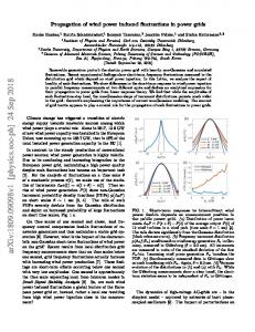
Figure 7. HVDC terminal control configurations and the corresponding DC voltage vs power characteristics Also, the control hierarchy could further be expanded on the top, for example by requiring the delivery of frequency control to the onshore grids, or voltage control, black start, fault ride through and others. Clustering of wind power The very ambitious plans with regard to wind power installations offshore in the North Sea suggest that a more intelligent management of the wind power production could help the system face the challenges linked to balancing and other system services. The definition of required system services is performed by the TSOs, based on the needs of their transmission system. Services such as power reserves, frequency control, voltage control and reactive power control are usually required to conventional power plants but will be extended to other elements, among which wind farms will certainly find room. Therefore, there is a need for the development of a wind farm cluster control, which permits a group of wind farms to harmoniously and effectively carry out such tasks, while delivering the power to the market. In the case of wind farms, other interesting features could be included in a cluster controller, which may help to perform congestion control, to dwarf the effects of an incoming storm, to smooth wind power variability thanks to geographical dispersion and so on. The hierarchical structure of a wind farm cluster controller can be sketched as in Figure 8. An agreement needs to be reached on the definition of wind farm cluster. Reference [21] proposes that a cluster of wind farms should include all the installations behind a certain grid node. On the other hand, should communication issues be overcome, the expansion of the concept of cluster to a larger area may be alluring. The main issues that need to be addressed in this field are the design of the hierarchy and the assessment of the necessary control tasks and the analysis of the influence of communication.
TSO(s)
Balancing responsible
Central Cluster Controller
Wind Power Plant Controller
Wind turbine controller
Wind turbine controller
Wind Power Plant Controller
Wind turbine controller
Wind turbine controller
Wind Power Plant Controller
Wind turbine controller
Wind turbine controller
Figure 8. Wind farm cluster controller principle and hierarchy
References [1] Pure Power; Wind energy targets for 2020 and 2030, EWEA 2011, http://www.ewea.org/fileadmin/ewea_documents/documents/publications/reports/Pure_Power_III.pdf, Accessed November 2011; [2] J. Arrillaga – High Voltage Direct Current Transmission, 2nd ed. , Institution of Electrical Engineers, London, U.K., 1998. [3] D. Van Hertem, M. Ghandhari – Multi-terminal VSC HVDC for the European supergrid: Obstacles, Renewable and Sustainable Energy Reviews 14 (2010), pp: 3156-3163 [4] Flourentzou, N.; Agelidis, V.G.; Demetriades, G.D.; , "VSC-Based HVDC Power Transmission Systems: An Overview," Power Electronics, IEEE Transactions on , vol.24, no.3, pp.592-602, March 2009 doi: 10.1109/TPEL.2008.2008441 [5] B. Bijlenga, “HVDC device for converting between alternating voltages and direct current voltages,” U.S. Patent 6 480 403, 2002. [6] A. Lesnicar, R. Marquardt, “An innovative modular multi-level converter topology for a wide power range”, IEEE Power Tech Conference, Bologna, Italy, June 2003. [7] C.C. Davidson and D.R. Trainer, “Innovative concepts for hybrid multi-level converters for HVDC power transmission“, IET Conf. Pub. 2010, O51 (2010), DOI:10.1049/cp.2010.0982 [8] http://www.alstom.com/, pdf file: “HVDC-VSC: transmission technology of the future” [9] “Components Testing of VSC System for HVDC Applications”, Cigré, February 2011. [10] Padiyar, K. R., “HVDC Power Transmission Systems - Technology and System Interactions”, John Wiley and Sons, 1990. [11] Tang, Lianxiang og Ooi, Boon-Teck, “Managing zero-sequence in Voltage Source Converter”, Conference Record of the 37th IAS Annual Meeting , Industry Applications Conference 2002. pp. 95-802, 2002, Årg. Volume 2. [12] Yang, Jie, et al., “Characteristics and Recovery Performance of VSC-HVDC DC Transmission Line Fault”. Power and Energy Engineering Conference (APPEEC) 2010 Asia-Pacific. pp. 1-4, 2010. [13] “VSC Transmission - Technical Brochure nr. 269.”, Cigré, Working Group B4.37. April 2005. [14] “Circuit-breakers for meshed multiterminal hvdc systems”, Cigré Technical brochure nr. 114., Joint Working Group 13/14.08, 1997. [15] De Decker, J. and Kreutzkamp, P. Offshore Electricity Grid Infrastructure in Europe – A Techno-Economic Assesment, Offshore Grid final report, October 2011. Accessible at http://www.offshoregrid.eu/images/FinalReport/offshoregrid_fullfinalreport.pdf [16] Gomis-Bellmunt, O. et al. Topologies of multiterminal HVDC-VSC transmission for large offshore wind farms, Electric Power System Research 81 (2011), 271-281 DOI:10.1016/j.espr-2010-09-006 [17] Zhou, H. et al. Grid integration of DFIG-based offshore wind farms with hybrid HVDC connection, Proceedings of the international conference on electrical machines and systems 2008.
[18] Yang, Y. et al. Contribution of VSC-HVDC connected wind farms to grid frequency regulation and power damping, Proceedings of the annual conference of the IEEE industrial electronics society, 2010, pp. 397-402. [19] Xiang, D. et al. Coordinated control of an HVDC link and doubly fed induction generators in a large offshore wind farm, IEEE transactions of power delivery, Vol. 21, No. 1, January 2006, pp. 463-471. [20] Nakajima, T. and Irokawa, S. A control system for HVDC transmission by voltage sourced converters, IEEE Power engineering society summer meeting, Vol. 2, July 1999, pp. 1113-1119, DOI:10.1109/PESS.1999.787474. [21] Haileselassie, T. et al. Multi-terminal VSC-HVDC system for integration of offshore wind farms and green electrification of platforms in the North Sea, Nordic workshop on power and industrial electronics, June 2008. [22] Haileselassie, T. et al. Control of multiterminal HVDC transmission for offshore wind energy, Nordic wind power conference, September 2009. [23] Gesino, A.J. et al. Wind farm cluster management system. ISET, Fachhochschule Stralsund XV Energie – Symposium, November 2008.