Available online at www.sciencedirect.com
ScienceDirect Energy Procedia 80 (2015) 237 – 244
12th Deep Sea Offshore Wind R&D Conference, EERA DeepWind'2015
DC voltage control for fault management in HVDC system Anastasios Oulis Rousis, Olimpo Anaya-Lara * University of Strathclyde, 16 Richmond Street, Glasgow G1 1XQ, UK
Abstract
This paper focuses on the transmission system options for connection of offshore wind farms and investigates the advantages and disadvantages of proposed concepts in order to draw a conclusion regarding their suitability for connection in the electricity system. Then, the most appropriate solution is implemented in Matlab/Simulink to show its benefits. For this purpose, 5 wind farms are connected to an offshore station and their power output is transferred onshore via a point – to – point DC link. Additionally a novel proposal of DC voltage control is included in the model to simulate the behaviour of the system when faults occur in the electricity grid. © 2015Published The Authors. Published by Elsevier Ltd. © 2015 by Elsevier Ltd. This is an open access article under the CC BY-NC-ND license (http://creativecommons.org/licenses/by-nc-nd/4.0/). Selection and peer-review under responsibility of SINTEF Energi AS. Peer-review under responsibility of SINTEF Energi AS Keywords: HVDC; VSC – HVDC; Voltage Control; Fault Management; Wind Energy
1. Introduction Renewable energy sources (RES) have recently raised great interest among the scientific circles. This is because of the increased concern for the environmental impact of conventional fossil fuel sources and also due to the energy crises in the early and late 70’s that caused dramatic increase at the price of conventional sources [1]. Consequently, discussion is being done between governments around the world and this has led to long-term targets regarding the energy use of countries. Specifically, Europe, which is among the continents with the greatest interest in the energy sector, has set the so-called ‘20-20-20’ European Union climate and energy package [2]. This corresponds to 20% decrease of gas greenhouse emissions and also 20% of Europe’s energy use coming from RES by the end of 2020. Another evenly important reason for the high growth of RES is the fact that the peak demand of the developing countries increases every year, as electricity constitutes the main component for the promotion of social welfare [1].
* Corresponding author. Tel.: +44-789-585-2651 E-mail address:
[email protected]
1876-6102 © 2015 Published by Elsevier Ltd. This is an open access article under the CC BY-NC-ND license (http://creativecommons.org/licenses/by-nc-nd/4.0/). Peer-review under responsibility of SINTEF Energi AS doi:10.1016/j.egypro.2015.11.427
238
Anastasios Oulis Rousis and Olimpo Anaya-Lara / Energy Procedia 80 (2015) 237 – 244
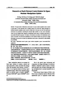
Within this context, countries are trying to reduce the consumption of conventional energy sources (oil, coal and so on) and their interest has already been turned to RES like wind power, solar, thermal and tidal. Wind energy is considered to have the greatest potential at the time being and for this reason every year more and more wind farms are installed both onshore and offshore. This raises a number of challenges, including converter and generator technologies and collection and transmission of produced power, that need to be addressed in order to increase the wind energy penetration levels [3, 4]. One of the major challenges is the transfer of the produced wind power from the distant offshore sites to the land. Voltage Source Converter – High Voltage Direct Current (VSC – HVDC) systems are considered the best available solution to the many issues alternating current based systems face. 2. Objectives One of the main targets of this paper is to present a VSC – based point – to – point DC system for dynamic simulation analysis of HVDC networks, which are considered of major significance for the development of offshore wind farms. Within this context, various transmission systems are presented for completeness of the subject before analysing the HVDC systems. The HVAC system employed in all the existing wind farms is analysed to show the disadvantages and why interest is nowadays turned into direct current systems. Then, discussion is done upon the classic HVDC systems, known as CSC – HVDC systems, in order to become clear to the reader that VSC – HVDC systems are in the forefront of offshore wind energy. At another level, the paper presents a novel strategy of DC voltage control for fault management. A big issue on the DC links is the transfer of energy when faults occur on the AC side of the grid. Specifically, when a fault occurs on the AC grid, the transmission of energy to the AC side is disrupted. However, the production of energy at the wind farms side is not curtailed and hence the energy continues to be injected into the DC link. The issue is that the injected energy does not have a way – out when it comes to simple point – to – point systems and this leads to increase of the DC voltage. In cases of major faults, such as three – phase short – circuits, the DC voltage may increase so much that it will destroy the link due to overloading. The proposed method gives a solution to this, as it encourages the communication between the two sides of the DC link and sends a command signal to the wind farms side anytime the DC voltage starts to increase. This command informs the wind farms controllers to curtail their output, as no more energy can be tolerated by the DC link. The proposed model is implemented in Matlab/Simulink. 3. Wind energy Among RES, wind energy holds the first place in terms of installed capacity worldwide. Specifically, the total wind power installed around the world was 159GW at the end of 2009 and in Europe the installed wind power capacity was 84.278GW in 2010 [5]. This amount corresponds to 16.8% of that year’s power capacity installations and brought renewables to the first place of new installed power capacity. Significant is the growth rate of the annual wind energy installations through the last 15 years starting from an installed capacity of 814MW in 1995 to reach 9,295MW in 2010, which gives the high rate of 17.6% annually. This trend is illustrated in Figure 1.
Figure 1 (a) Annual wind power installations in EU in MW [5]; (b) Offshore’s share of annual EU wind power market in MW [5]
Anastasios Oulis Rousis and Olimpo Anaya-Lara / Energy Procedia 80 (2015) 237 – 244
239
The largest of this amount of energy has been installed onshore (8,412MW accounting for 90% of overall installations). Due to the high growth rate of the onshore wind farms that have been installed all these years the suitable onshore wind farm sites have become extinct. Therefore, offshore wind farms have been rapidly growing [5]. This abrupt change in the wind market (commenced in 2007) happens for a plethora of reasons:
The space is no longer an issue, as large, unfulfilled areas exist across the seas and oceans [6]. The mean wind speed is higher than the one in onshore sites [4, 6]. The turbulence is much lower (meaning higher power quality), as the surface is much smoother. Visual and noise impact is minimised (even extinct for offshore wind farms installed in significant distances from the coast) [7]. These factors have made the offshore wind power installations to rise significantly through the years.
4. Challenges in offshore wind energy Although offshore wind energy is highly promising for the near future, many challenges are still to be overcome. First of all, a major issue is the structure of turbines’ foundations, as at the moment structures are very light to withstand the great horizontal loads, to which they are subjected [8, 9]. In addition to this, connection of offshore wind farms is another challenge. Currently, High Voltage Alternating Current (HVAC) cables are used for the transfer of the produced energy, but it is expected that HVDC will be deployed for such use. The latter have the great advantage of reduced power losses and also capability of transmitting more power in larger distances per cable [10]. It is not only the cabling system that needs upgrade but the overall grid infrastructure in order to ensure high levels of integration of wind energy into the transmission and distribution systems. This is highly important, as in this way the electricity grid will become suitable for increased transnational and regional electricity transport [11]. Another key aspect for the development of offshore wind farms is the turbine technologies. Development of the next generation of offshore wind turbines is a key factor for the new offshore wind industry and hence concepts of large scale wind turbines (reaching even 20MW) are being explored [12]. Moreover, necessity is the development of appropriate hardware and software to provide more accurate wind measurements to be used in designing high resolution offshore wind atlases [12]. Finally, cooperation between the grid operators is required as due to the increased penetration of wind energy into the system some technical requirements (like active and reactive power control, power quality, etc.) are changing. As far as the transmission system options are concerned, two are the main challenges that offshore wind energy faces at the moment; the collection of wind power and the transmission of collected power onshore [3]. The collection of wind power is done by the offshore collection system, which is responsible for gathering the wind turbine generators’ (WTG) power output and transferring it to a central point in order to be injected into the main grid [13]. The options for collecting the produced power are various such as String or Star Cluster layout; the String Cluster configuration has prevailed. According to this, a number of WTGs are connected to a distribution feeder with sufficient voltage level to carry the produced power. Then, all distribution feeders are connected to an offshore substation to step up the voltage in the appropriate transmission level. Regarding transmission of produced power from the offshore collection point onshore, the two main options are the HVAC and HVDC systems. These are divided into the following three major categories [3]: HVAC system option: This option is not considered to be appropriate for long distance transmission systems due to its high power losses, which are caused by the stray capacitances of the AC cables. Current Source Converter (CSC) – HVDC system option: This option is also not preferable, as special arrangement is needed at the side of the wind farm to facilitate the operation of line –commutated converters. Voltage Source Converter (VSC) – HVDC system option: It represents the best available choice, as it overcomes the drawbacks of the first two options.
240
Anastasios Oulis Rousis and Olimpo Anaya-Lara / Energy Procedia 80 (2015) 237 – 244
The following table summarises the main characteristics associated with every option: Table 1. Comparison between HVAC, CSC – HVDC and VSC – HVDC HVAC Capacity distance dependent? Power losses Black – start capability Voltage level transform AC system support Fault limitation Short-circuit level limitation
CSC-HVDC
VSC-HVDC
×
×
Distance dependent Limited × ×
2-4%
5-10% × ×
Limited
× Large range
Evolution in components
Not expected to decrease
Cost of semiconductors tends to decrease with time
Cost of semiconductors tends to decrease with time
Visual impact
Greater as dimensions are larger
HVDC subsystems require smaller space
HVDC subsystems require smaller space
Protection systems
More advanced
Limited
Limited
Control strategies
Acceptable under normal operating conditions
Fast control
Fast control both under normal and fault conditions
Corona phenomena
Annual mean Corona losses are much lower in HVDC systems.
Radio interference
As Corona phenomenon is limited, the radio interference is also limited in DC lines.
Audible noise
During rainy condition DC lines appear to have lower noise levels than AC lines.
Emissions
Emissions of positively charged ions, O3, N2 and free electrons by DC lines are not a concern. The same does not state for AC lines though.
5. DC Voltage Control during faults When faults occur in the AC grid, the transfer of the produced energy is disrupted. Therefore the wind farms output should be curtailed to ensure security of the DC link. The below proposed method establishes communication between the two sides of the link to prevent the DC voltage increase. The principle of its operation lies upon the steadiness of the DC voltage. Specifically under normal operating conditions the DC voltage is constant to a value, whereas when a fault occurs it rises (Figure 2). In the first part of the curve, the rate of change of the DC voltage is zero, whereas after the fault the rate increases. This abrupt change in the rate can lead to a fault recognition. For this reason, a block has been developed to measure the DC voltage and calculate its rate of change. The output corresponds to a Boolean parameter, which is zero in case of zero rate of change of voltage. When the fault occurs in the AC grid, the DC voltage rises due to the uninterrupted power transfer from the wind farms side and the Boolean parameter becomes equal to one. Thus, the Boolean parameter, which triggers the control system, is sent to the wind farms as a command signal to their controllers to calculate a new active power output reference value. A filtering logic has also been implemented in order to avoid false triggering of the control system as a result of other transients. The custom filter comprises of a ‘saturation block’, which plays the role of a threshold. This threshold has been set to be ±7% of the steady state value of VDC. This empirical value came from observation of the DC voltage graph
Anastasios Oulis Rousis and Olimpo Anaya-Lara / Energy Procedia 80 (2015) 237 – 244
241
Figure 2 Example analysing how the controller acts.
during various simulations; it has been observed that the deviation of the voltage does not exceed ±7% around VDC when in steady state operation. Moreover a time delay of 0.05 sec has been applied to avoid the system from tripping immediately. This enables the system to ‘recognise’ other transients that do not correspond to faults. The output of the developed block (Pref_cmd) is fed back to the sub – block of each wind farms controller that generates the active power reference value to inform it that the reference value should be set lower in relation to the severity of the fault; the severity of the fault corresponds to the calculated slope of the DC voltage (dVDC/dt). This means that the more severe is the fault, the bigger is the slope. Furthermore, it has been observed that in some instances due to the severe nature of the implemented faults, the control system tends to reduce the active power output considerably in a way to compensate them. However, this is not considered realistic and hence appropriate block (saturation block) was employed in order to set a minimum value (Pref, limit), at which the active power can be reduced as a result of the operation of the controller. The reason for not considering as realistic the reduction of active power to zero instantly relates to the inertia constant of the wind turbine generators. Specifically, WTGs turn with high rotational speeds and this means that they cannot stop instantly, but they need a certain amount of time before stop generating power. Forced stopping would destroy them and the moving parts might even break. What is more on this, the low set point value of the saturation block has been set close to the active power output command of this wind farm that operates in the minimum load. In this way, higher reduction of the power of wind farms that operate closer to the rated output is achieved. This is desirable as it is not considered acceptable that offshore wind farms halt operation at any time. The implementation of this ‘logic’ for the reduction of the power output was one of the objectives. The operation of the controller, implemented in Simulink, is summarised in the flowchart of Figure 3.
Figure 3 Flowchart illustrating the control algorithm
242
Anastasios Oulis Rousis and Olimpo Anaya-Lara / Energy Procedia 80 (2015) 237 – 244
6. Test cases A generic point-to-point VSC-HVDC system has been developed in Matlab/Simulink to test the proposed control method. It has been built in a way to integrate significant amount of produced wind energy from the offshore wind farms to the onshore AC grid. It includes 5 offshore wind farms capable of producing 250MW each at their maximum operation. The wind farms are dispersed into the sea in distances that vary from the offshore converter station (0 – 20km). Moreover, as the model tries to discover the behaviour of a system that could be developed in the near future, the offshore converter station is located 300km far from the land. The employed converter is an average – model based VSC comprising of 3 bridge arms. The power electronic devices for such an application could either be IGBTs or GTOs. The voltage level during normal operation of the system is around 650kV. It should be noted that existing technologies cannot handle so high voltage and power levels. It is believed, though, that advances in the power electronics area will allow such applications within the next years. The implemented model has been used for simulation of various faults under different active power output levels. It has been found that the benefits of the proposed control strategy can be best observed when three – phase and single – phase to ground faults are performed in the system. The procedure will be presented for active power output of 1GW for a single – phase to ground fault lasting 200msec and for a three – phase fault lasting 80msec. 6.1 Single-phase to ground fault for 200msec A single – phase to ground fault has been selected for simulation. These types of faults belong to the so – called unbalanced faults. They are considered significant, as they are the most common faults that occur in power systems (70% of all transmission faults are classified as phase to ground faults) [14]. Operation of the proposed control system for fault duration of 200msec is illustrated in Figure 4.
Figure 4 (a) Active power with control system disabled (blue) and enabled (green); (b) DC voltage with control system disabled (blue) and enabled (green).
Anastasios Oulis Rousis and Olimpo Anaya-Lara / Energy Procedia 80 (2015) 237 – 244
Figure 5 (a) Active power with control system disabled (blue) and enabled (green); (b) DC voltage with control system disabled (blue) and enabled (green).
6.2 Three – phase to ground fault for 80msec This type of fault belongs to the category of balanced faults. Even though they are the most rare (only 5% of the faults) [14], they represent the most severe case and hence they are investigated. This fault has been investigated for 80msec duration. Operation of the controller in this case is illustrated in Figure 5. It would be expected that the system would have significant correction of the DC voltage. However, this is not the case and therefore it is assumed that the operation of the proposed controller has flaws, which will be discussed in the conclusions. 7. Conclusions A control strategy regarding fault management has been proposed in paragraph 5 to analyse an innovative way to control the DC voltage when faults occur in the AC – side of the grid. As explained, the proposed control strategy tries to resolve the issue that comes up in the existing point – to – point HVDC systems when faults occur in the AC grid and the transfer of energy is disrupted. The developed system achieves an established ‘communication’ between the two sides and sends command signals to the wind farms to curtail their output. The test cases have included single – and three – phase to ground faults for 200msec and 80msec during high wind power penetration. Table 2 summarises the main aspects observed from the operation of the controller. Table 2. Results of the control system when the wind power penetration into the AC system is 1GW Type of fault Active power DC voltage (kV) Response of the output (MW) system Control Control disabled enabled Normal operating conditions
1050
650
N/A
N/A
Single – phase to ground fault for 200msec
890 during the fault, with control enabled
950
840
Returns to initial condition at half time
Three – phase to ground fault for 80msec
900 during the fault, with control enabled
1150
1100
Faster return
The performance of the proposed control strategy is considered effective. The results prove that the control system not only restricts the excessive increase of the DC voltage (up to 110kV), but also helps the DC voltage to return faster to its initial condition. More tests have been performed which revealed in some cases constraint of the DC voltage of more than 300kV. In such a case the control strategy would be necessary for the security of the DC link. On the other hand, it has been
243
244
Anastasios Oulis Rousis and Olimpo Anaya-Lara / Energy Procedia 80 (2015) 237 – 244
revealed that the DC voltage controller tends to trip without any faults occurring on the AC network. This is due to the customised filter that has been employed to mitigate this tripping; optimisation of the filter would be required. 7.1 Future work The simulated test cases revealed some flaws of the developed model and control system. It is recommended that the model will be optimised so it can simulate wider range of test cases (e.g. additional wind farms for higher wind power output). Furthermore, an efficiently configured filter would offer more possibilities to the proposed control strategy as the employed one leads to false tripping. Additionally, it is believed that in near future offshore wind farms will take part in the power trading between the various interconnected countries (European Supergrid and so on). For this reason, the next step in the HVDC technology is the multi – terminal DC (MTDC) systems. The MTDC systems gather a number of benefits that make them suitable to cover future needs [3]: Larger interconnected systems withstand the loss of a unit. When more generating plants are available, the grid operator can optimise the dispatch and reduce energy price. As MTDC systems will achieve interconnection of dispersed generating plants, the need for reserve will be reduced. The reliability and security of supply will increase, as more plants will be available at any time to cover for the demand. As MTDC will increase the penetration of wind energy into the AC system, this will be translated in carbon dioxide reduction. Apart from the development of MTDC systems, even VSC – HVDC systems face a variety of barriers to overcome such as protection systems, VSC losses, DC transmission level voltages and many more. [3, 15]. References [1] Pinto, R. Teixeira, et al. "Comparison of direct voltage control methods of multi-terminal DC (MTDC) networks through modular dynamic models." Power Electronics and Applications (EPE 2011), Proceedings of the 2011-14th European Conference on. IEEE, 2011. [2] Da Graça Carvalho, Maria. "EU energy and climate change strategy." Energy 40.1 (2012): 19-22. [3] O. Anaya – Lara et al., “North Sea Offshore Networks Basic Connection Schemes: Dynamic Performance Assessment” presented at EPE Joint Wind Energy and T&D Chapters Seminar, Trondheim, 2011. [4] Delay, T., et al. “Offshore Wind Power: Big Challenge, Big Opportunity-Maximising the environmental, economic and security benefits”, Carbon Trust, 2008. [5] “Wind in power, 2010 European statistics”, European Wind Energy Association, 2011. [6] Wind Atlas. Available: http://www.wasp.dk/Wind-Atlas/. [7] “The European offshore wind industry-key trends and statistics 2009”, European Wind Energy Association, 2010. [8] Houlsby, Guy. Offshore Wind Turbines: Some Technical Challenges, Oxford University, 2003. [9] Lawson, J. (2011, August 11). What are the challenges and innovations in offshore wind design and development? [Online]. Available: http://www.renewableenergyworld.com/rea/news/article/2011/08/what-are-the-challenges-and-innovations-in-offshore-wind-design-anddevelopment. [10] Papalexandrou, M. (2011, October 11). Planning for the challenges of offshore wind [Online] Available: http://www.renewableenergyworld.com/rea/news/article/2011/10/planning-for-the-challenges-of-offshore-wind. [11] Zervos, A., et al., “Wind Energy-The facts, Executive Summary”, European Wind Energy Association, 2009. [12] Fichaux, N., et al., “Oceans of Opportunity-Harnessing Europe’s largest domestic energy resource”, European Wind Energy Association, 2009. [13] Bresesti, P.; Kling, W.L.; Hendriks, R.L.; Vailati, R., "HVDC Connection of Offshore Wind Farms to the Transmission System," Energy Conversion, IEEE Transactions on , vol.22, no.1, pp.37,43, March 2007. [14] Santamaria, J., “Analysis of power systems under fault conditions”, M.S. thesis, EEE, CalState, Sacramento, CA, 2011. [15] Haileselassie, Temesgen Mulugeta. "Control, dynamics and operation of multi-terminal VSC-HVDC transmission systems." (2012). [16] Meah, K.; Ula, S., "Comparative Evaluation of HVDC and HVAC Transmission Systems," Power Engineering Society General Meeting, 2007. IEEE , vol., no., pp.1,5, 24-28 June 2007. [17] Padiyar, K. R. HVDC power transmission systems: technology and system interactions. New Age International, 1990. [18] Kim, Chan-Ki, et al. HVDC transmission: power conversion applications in power systems. John Wiley & Sons, 2009.