A routing algorithm for the K-star, which takes no more than L3(« - l)/2j steps to route a message from any given node S to a destination node D, was given in. [8].
Deadlock-free wormhole routing algorithms for star graph topology C.P.Ravikumar A.M.Goel
Indexing terms: Parallel processing, Routing algorithms, Routing optimisation
Abstract: For constructing massively parallel multicomputers with over 5000 processing nodes, the Star Graph topology is known to be better than the hypercube in terms of the average routing distance, the number of links per node, and the fault diameter. The authors present two deadlock-free algorithms for routing in Star Graph, assuming the Wormhole routing model. Both the algorithms use the concept of virtual channels introduced by Dally and Seitz. The first algorithm is non-optimal in terms of the average routing distance, but uses fewer virtual channels on the whole. The second algorithm is optimal in terms of routing performance, but requires a somewhat larger number of virtual channels per node.
t = 5«(«)
where g, is the rth 'generator' function which simply swaps the symbol st, with s{. The following properties of the Star Graph were proved by Akers and Krishnamurthy [8]. (a) Star Graphs are node-symmetric and edge-symmetric. (b) The degree of a node in an «-star is {n - 1) (c) The H-star is maximally fault-tolerant, with a fault-tolerance of (n - 2). (d) The communication diameter of the «-star is L3(H - l)/2j. (e) The average distance between two nodes in an nstar is n - 4 + Hn + 2/n, where Hn is the nth Harmonic number. 1234
1
4231
Introduction
Message-passing multiprocessors based on direct interconnection networks have become popular in building massively parallel systems with over 5000 nodes. The hypercube interconnection network, for instance, has been used in many existing commercial parallel processors such as the Intel iPSC/860 [7], NCUBE/7 [3], and the Connection Machine [4]. More recently, Akers and Krishnamurthy [8] introduced a class of graphs, known as Cayley Graphs, on which communication-efficient interconnection networks with good fault-tolerance properties can be constructed. A particular subclass of Cayley Graphs, known as Star Graphs, are known to outperform the hypercube in terms of the average distance, the number of links per node, and the fault diameter when the number of processing nodes is over 5000 [8]. An n-star graph consists of n\ nodes labelled using permutations of 1 2 ... n. Two nodes labelled s and t are joined by an edge iff t can be obtained by swapping the first (left most) symbol of s with any other symbol of s. For instance, a 4-star has 24 nodes; the node labelled 1234 is connected to 3 other nodes 2134, 3214, and 4231. Fig. 1 shows the topology of a 4star. If the label t can be obtained by swapping the z'th symbol of s with the first symbol of s, we write IEE Proceedings online no. 19952221 Paper first received 13th October 1994 and in revised form 6th July 1995 The authors are with the Department of Electrical Engineering, Indian Institute of Technology, New Delhi 110016, India IEE Proc.-Comput. Digit. Tech., Vol. 142, No. 6, November 1995
314 2 Fig. 1
4-star topology
7.7
Wormhole routing
2143
Inspired by computer networks, early multicomputers made use of store-and-forward routing technique, where the entire message is buffered at each intermediate node before the message is forwarded to the next node in the path [6]. In store-and-forward routing, the communication delay is large and is directly proportional to the length L of the path along which the message is routed. Dally and Seitz [2] introduced a routing technique called Wormhole routing, which overcomes the above disadvantage. In a Wormhole-routed network, each message packet is subdivided into flow control digits (flits). Flits are routed from the source to the 395
destination in a pipelined fashion. Thus, the header flit can arrive at the destination even before the last flit of the message has left the source. All flits that belong to a message packet make use of the same set of communication channels. In Wormhole routing, the communication delay depends mainly on the bandwidth of the communication channels. Several commercial machines such as the Intel iPSC/860 and research prototypes such as the J-machine have adopted the Wormhole routing technique [6]. A disadvantage of Wormhole routing is that deadlocks can occur if special precautions are not taken to avoid deadlocks by carefully restructuring the routing algorithm [2]. Dally and Seitz presented deadlock-free routing algorithms for several network topologies such as the fc-ary «-cube, the Shuffle-Exchange network, and the Cube-connected Cycles [2]. In this paper, we present two deadlock-free algorithms for the Star Graph topology. node 123 312
312
312
C
CO
r-o
00
CO rsj
C
231
i~
123
123
123
node 231
213
213
node 321
C123
CO
213 ro CO
node 312
321
r-o
321
CO
r-o
node 213
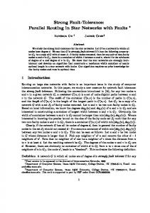
node 13 2 Fig.2
Deadlock situation in a 3-star
A routing algorithm for the K-star, which takes no more than L3(« - l)/2j steps to route a message from any given node S to a destination node D, was given in [8]. However, the Akers-Krishnamurthy routing algorithm is not deadlock-free, as can be seen in the example of the 3-star (see Fig. 2). We label the channels of the 3-star cs, where s is the label of the source node of the channel. Using the Akers-Krishnamurthy algorithm, the node 213 must forward the flit received along channel c123 onto the channel c132. Following [2], we construct a channel dependence graph G which has one node corresponding to each channel. A directed edge exists from a node c( in G to a node c,- if a flit is presently on channel c, and the routing algorithm would send the flit onto the channel Cj in the next step. If each channel is associated with a flit-buffer of size 3, a deadlock situation occurs in this example, where no flit can progress towards its destination. Dally and Seitz showed that a routing algorithm is deadlock-free if and only if the channel dependence graph G induced by the routing algorithm does not contain any directed cycles. We shall ensure this by restricting the routing such that a directed edge exists in the channel dependence graph from channel ct to channel Cj only if i > j.
1.2 Organisation In the following section, we present a routing algorithm for the K-star that is similar to the e-cube algorithm for Hypercube [2]. While the e-cube algorithm is deadlock396
free, our e-star algorithm is not; we show how the estar algorithm can be rendered deadldck-free [5] using the concept of virtual channels introduced by Dally and Seitz. However, as we shall prove in Section 2, it turns out that the e-star algorithm is not optimal in terms of the average routing distance. In Section 3, we present a 'cycle merging' routing algorithm which is optimal and deadlock-free. The two algorithms are compared and conclusions are drawn in Section 4. 2
The e-star algorithm
The e-cube routing algorithm for a binary K-cube routes a message originating at source S by 'correcting' one bit at a time, starting from the most significant bit of S. For instance, a message originating at 10110 and intended for the destination 01101 in a 5-cube will be routed along the path 10110-00110-01110-0110001101. The e-cube algorithm, which can also be generalised for the k-ary «-cube, is deadlock-free [2]. We can derive a similar algorithm for routing in the n-star. This algorithm, which we call the e-star, corrects the source label S one position at a time, starting at the rightmost position. As an example, a message originating at node 2341 and intended for destination node 1234 will be routed along the path 2341-4321-13243124-2134-1234. procedure e-star (s, D, n, M); begin /* Route message M from node S to node D in an nstar */ SO: if S = D then consume M; else begin SI: Find largest i < n such that D(z) =t S(z) if S(l) = D(z) then begin S2: T := g,(S); e-star (T, D, n, M); end else begin S3: Find 7 such that S(/) = D(z); T := g/S); e-star (T, D, n, M); end end end The e-star algorithm may be understood using the concept of sub-stars in a star graph. In the n-star, consider the subgraph induced by all those nodes whose labels have the symbol i fixed in their jth. position; we denote this subgraph by ij. For instance, 243 represents the subgraph induced by the nodes 1324, 3124, 1423, 4123, 3421, 4321. It is easy to see that ij is a sub-star when j > 1 [8]. Given a node s, we denote the sub-star induced by keeping s(J) s(j + 1) ... s(ri) fixed in their positions by y(Sj), 1 < j < n. It is easy to see that \|/(^) is also a sub-star. The basic idea behind the e-star algorithm is to check if the source S and destination D are on the sub-star \]/(Dn); if not, the algorithm routes the message to a node which is on the sub-star \|/(Dn). Thus the algorithm has 'corrected' the last symbol of S to match the last symbol of D. This procedure is repeated, until all the symbols of S are corrected to match the symbols of D. Theorem 1: The e-star algorithm correctly routes a message from a source S to destination D. IEE Proc.-Comput. Digit. Tech., Vol. 142, No. 6, November 1995
Proof: Given the label of the current node S and the destination node D, we define the function f[S, D) to be the largest index i such that S(z') t- D(z). When S = D, the function/is defined to be 0. Suppose that the estar algorithm routes the message from a node P to node Q. Then it is necessarily true that f(Q, D) < /(P, D), where D is the destination node. This may be seen by looking at Steps SI and S3 in the above algorithm. Step SI evaluates i = f(S, D). If the algorithm takes Step S2, T is computed to be g,(S), in which case T(z) = D(r'). Furthermore, the generator g, only changes the z'th and 1st symbols of S. Therefore, /(T, D) is at least one less than f(S, D). If the algorithm takes Step S3, then /(T, D) = f[S, D) since 1 < j < i. We now claim that whenever the e-star algorithm takes the Step S3, the following call of e-star will take Step S2. If T is the node to which Step S3 routes the message, then T(l) = S(/) = D(i). In the following call of e-star, T takes on the role of S, and hence S(l) = D(/), forcing the algorithm to execute Step S2. Further, Step SI ensures that the algorithm will only stop forwarding the message if /(S, D) = 0. Hence the proof. Theorem 2: The e-star algorithm takes no more than In - 3 steps to route a message on an «-star. The average routing distance achieved by the algorithm is 2« + 1 -
mn. Proof: For correcting any position in the permutation corresponding to S, the e-star algorithm requires either no forwarding, a single forwarding step (Step S2), or two forwarding steps (Step S3 followed by Step S2). In the worst case, the algorithm takes 2 forwarding steps to correct each of the rightmost (n - 2) symbols, and then uses the Step S2 to correct the second symbol. Let T(«) be the average routing distance between any two nodes S and D on an «-star. Using the e-star algorithm, routing on an n-star is equivalent to correcting the rightmost position and then routing on the n - 1 substar. The symbol required to correct the rightmost position can be in any of the n positions of S with equal probability. If this symbol is in the first position, one forwarding step is required to correct the rightmost position. If the symbol is already in the rightmost position, no forwarding step is required to route to the substar. Finally, if the symbol is in any other position j, 1 < j < n, two forwarding steps become necessary (Step S3 followed by Step S2). Hence, the following recurrence relation results for T(«). T(n)= (- x 0 + - x l + — -
V
n
n
(1)
n
It is easy to see that the basis T(2) = V2. Solving the recurrence gives the required formula for T(n). Theorem 3: The e-star algorithm of Fig. 3 is not deadlock-free.
share the same physical channel, but use independent flit buffers. The notation used in this section is shown as follows x, y, z
permutations on n symbols
nx
node labelled using permutation x
sym(y, d) dth symbol of permutation y sJj) permutation obtained by applying generator gd to y i.e., by changing sym(y, 1) and sym(j, d) c
physical channel from node ny to ngn.k(y)
ns nD
Source node Destination node
ky
R(c, nz)
Routing function R returns the channel along which a message received on channel c and destined for node nz will be routed. We split the physical channel cky into (k + 1) virtual channels. A virtual channel is labelled cvky, where v indicates the virtual channel number (n - k) < v < n. Thus cvky is the virtual channel labelled v and shares the physical channel cky which in turn connects node n y to ngn.k(j,y We modify the e-star algorithm as shown below; for convenience, we use d = (n - k).
if Vj > d! sym(gd(y),j) = sym(z,j) f\ sym(gd(y),d') # sym(z,d') /\ sym(gd(y),l) = sym(z,d') Cd',n — i,gd(x)
if Vj > d' sym(gd(y),j) = sym(z,j) f\ sym(gd(y),d') / sym(z,d') f\ sym(gd(y),i) = sym(z,d')
We refer to two equations above as Rules 1 and 2 respectively. Thus both the rules use the J'th virtual channel for routing, where d is the rightmost position in which the current node differs from the destination. Rule 1 is the case when the required symbol is in the first place, and Rule 2 is the complementary case. Theorem 4: The routing function Re_star is deadlockfree. Proof: It is enough to show that the routing algorithm Re-star routes in the decreasing order of channel subscripts. Let cvkx be the channel along which the message is received, and let cv',k',gn_k(x) be the channel along which the message is routed. We intend to show that
v k x > v' x' gn~k(x)
Proof: For the routing pattern of Fig. 2, the e-star algorithm behaves identically as the Akers-Krishnamurthy algorithm, thereby inducing a directed cycle in the channel dependence graph.
If channel cvXx was opted for by Rule 1, then we are assured that v > v' since v = f{x, z) and k = n - v; therefore,
2.7 Making the e-star deadlock-free
If channel cvkx was chosen by Rule 2, then we are assured that v = v' and k > kf because v = fix, z), n - k < v and therefore
We use the concept of virtual channels introduced by Dally and Seitz [2] to achieve deadlock-free e-star routing. Each communication channel in the «-star is divided into virtual channels; these virtual channels IEE Proc.-Comput. Digit. Tech., Vol. 142, No. 6, November 1995
v' = f(gn-k(x),z) = f(gv(x),z) < v
v'
- f{gn-k(x),z)
= f(x,z) 397
since (n — k) < v. This further implies that v = v'. Also, since Rule 2 is followed by Rule 1, we have in - V)
2.2
Number of virtual channels
Theorem 5; It is sufficient to split the physical channel cky into (k + 1) virtual channels, i.e., no more virtual channels are necessary. Proof: When a packet intended for node nz is routed along cvkx, we have/(x, z) = v. Rule 1 is used if sym(x, 1) = sym(z, v) and we use v = (n - k). Rule 2 is used if sym(x, i) = sym(z, v) for i > 1; in this case, we use i = (n - k). We claim that when Rule 2 is used 2 < i < v. This is because, for j > v, sym(x,y) = sym(z, j). Thus, in either case, (« - k) < v. Therefore, we divide the physical channel cky into (k + 1) virtual channels labelled cv,k,x' (n-k)