Even the most skilled robotics engineer is not able to identify and enumerate all ..... and its software components [3] (send parameters/configura- tions; switch ...
Dealing with Run-Time Variability in Service Robotics: Towards a DSL for Non-Functional Properties Juan F. Ingl´es-Romero1 , Alex Lotz2 , Cristina Vicente-Chicote1 and Christian Schlegel2 Abstract— Service robots act in open-ended, natural environments. Therefore, due to combinatorial explosion of potential situations, it is not possible to foresee all eventualities in advance during robot design. In addition, due to limited resources on a mobile robot, it is not feasible to plan any action on demand. Hence, it is necessary to provide a mechanism to express variability at design-time that can be efficiently resolved on the robot at run-time based on the then available information. In this paper, we introduce a DSL to express run- time variability focused on the execution quality of the robot (in terms of non-functional properties like safety and task efficiency) under changing situations and limited resources. We underpin the applicability of our approach by an example integrated into an overall robotics architecture.
plots given partial information while taking into account additional properties like safety and resource awareness). This motivates a different approach: (i) we need to make it as simple as possible for the designer to express variability at design-time and (ii) we need the robot to be able to bind variability at run-time based on the then available information. At design time, we also specify which problem solver (symbolic planner, constraint solver, etc.) to use to bind which variation point [2], [3]. At run-time, the robot then involves the prearranged and dedicated problem solvers. Overall, this improves task execution quality, optimizes robot performance and cleverly arranges complexity and efforts between design-time and run-time.
I. I NTRODUCTION Advanced robotic systems like service robots (robot companion, elder care, home health care, robot co-worker) are expected to robustly and efficiently fulfill different tasks (multipurpose systems) in complex environments (domestic, outdoor, public spaces). While robots are always only equipped with a limited set of resources (processing power, energy supply, sensing capabilities, skills), real-world environments are inherently open-ended and show a huge number of variants and contingencies. Thus, for many different situations, a robot needs to know how to spend its scarce resources in the most appropriate way (in short, acting efficiently) in order to achieve a high degree of robustness and to maintain a high success rate in task fulfillment. Although to date the focus still is mostly on pure task achievement (i.e., on robot functionality like in [1]), balancing non-functional properties (e.g., quality of service, safety and energy consumption) becomes more and more important and cannot be ignored in advanced service robotic systems. Even the most skilled robotics engineer is not able to identify and enumerate all eventualities in advance and to properly code configurations, resource assignments and reactions at design-time (not to mention that this is not efficient at all due to the combinatorial explosion of possible situations and skill parameterizations). Unfortunately, it is also not possible just to (re)plan at run-time in order to take into account latest information as soon as it becomes available. The computational complexity of planning is far too high when it comes to real-world problems (i.e., generate action 1 J.F. Ingl´ es-Romero and C. Tech. Univ. of Cartagena,
Vicente-Chicote are with ETSIT, Spain, {juanfran.ingles,
cristina.vicente} at upct.es 2 A. Lotz and C. Schlegel are with the Computer Science Department, University of Applied Sciences Ulm, Germany {lotz, schlegel}
at hs-ulm.de
How to get the coffee to the customer as hot as possible?
Fig. 1.
Our robot Kate makes coffee
Let’s illustrate this by an example scenario: a service robot delivers coffee on demand (see fig. 1). In order to optimize the coffee delivery service, the robot has to trade-off various aspects to come up with an optimized quality of service. The robot needs to be able to select an appropriate velocity (variation point) to properly fulfill its task according to further issues like safety and energy: (i) customers are satisfied only if the coffee has at least a certain temperature but prefer it as hot as possible, (ii) however, the maximum allowed velocity is bound due to safety issues (hot coffee) and also by battery level, (iii) since coffee cools down depending on the time travelled, a minimum required average velocity (depending on distance to customer) is needed, although driving slowly makes sense in order to save energy, (iv) nevertheless, fast delivery can increase volume of coffee sales. The late binding of variability (variation points purposefully left open by the designer) allows for a clever way of complexity handling according to the following principles:
Separation of concerns: a model (e.g., a task net) describes how to deliver a coffee (i.e., the action plot) [3]. Further models specify what is a good way (policy) of delivering a coffee (e.g., in terms of non-functional properties like safety or energy consumption). Separation of roles: the designer provides at design-time the models (action plots with variation points to be bound later by the robot, policies for task fulfillment, problem solvers to use for binding of variability). The robot decides at run-time on proper bindings for variation points by applying the policies and taking into account current situation and context. With this approach, the design-time modeling effort stays feasible even when extending task plots to non-functional properties like safety and energy consumption. On the other hand, even under non-functional constraints, run-time decisions on variation points become feasible due to narrowed search spaces. At the same time, this allows to much better address open-ended environments since policies (what is a good way of parameterizing a task plot) can come up at run-time with bindings of variability without enumerating all possible situations in advance. However, this requires means to express variability at design-time – in particular on non-functional properties – such that it can be exploited at run-time. In this paper, we introduce a first version of a DomainSpecific Language (DSL) for expressing run-time variability. It provides a mechanism to specify how a system should adapt to cope with changing situations in order to maintain or improve the execution quality of the system (in terms of nonfunctional properties like safety and task efficiency). We also describe the integration of the DSL into an overall robotics architecture. A real-world example underpins the feasibility of the approach and illustrates its benefits. We conclude with hints on next steps towards a full-fledged DSL and system integration. II. VARIABILITY M ODELING L ANGUAGE In this section we present the Variability Modeling Language (VML) that provides a mechanism to express how a system should adapt at run-time based on non-functional properties and adaptation rules. First, we introduce the overall idea behind the proposed language. After that, we address the VML syntax and the specification of the semantics. A. Overview Following the coffee-delivering example presented in the introduction, the service quality of a system can be given in terms of non-functional properties, such as, safety, performance and energy consumption. These properties are often contradictory and conflicting, and their importance varies according to the current system context (e.g., if the battery of the robot is low, energy consumption has a higher priority). Properties are expressed as functions of variation points, i.e., system variables left open at design time and bound at runtime (e.g., the average velocity impacts on performance since a fast delivery can increase the volume of coffee sales).
Therefore, binding variation points results in a certain quality of service (e.g., depending on the concrete value for the average velocity, the robot is more or less efficient, safe or energy consuming). The objective is to maximize the quality of service through the configuration of the variation points each time the system context changes significantly. Finally, the variation points can be constrained depending on the context using adaptation rules. As shown in figure 2, we have already presented all the keys of VML: variation points, context, properties and adaptation rules. VML model Variation points Contexts QoS properties Adaptation rules
Fig. 2.
input
(context values)
output
(variation point bindings)
System Components SmartTCL ...
VML Models and the interaction with the system (see sec. III)
B. VML Syntax Listing 1 shows the EBNF grammar of the VML language. The use of VML will be later illustrated in section IV with full-fledged examples. VMLModel ::= ( TypeDefinition | VariableDefinition | AdaptationRule )+ TypeDefinition ::= EnumType | NumericType | BooleanType EnumType ::= ’enum’ ID { ( EnumLiteral ; )+ } EnumLiteral ::= ID (’(’ INT ’)’)? NumericType ::= ’number’ ID ’{’ ’range’ ’:’ ’[’ (REAL|INT) ’,’ (REAL|INT) ’]’ ’;’ ’precision’ ’:’ (REAL|INT) ’;’ ( ’unit’ ’:’ STRING ’;’ )? ’}’ BooleanType ::= ’boolean’ ID ’;’ VariableDefinition ::= GeneralVar | Context | VariationPoint | Property GeneralVar ::= ’var’ ID ’:’ ID ’=’ expr ’;’ Context ::= ’context’ ID ’:’ ID ’;’ VariationPoint ::= ’varpoint’ ID ’:’ ID ( ’;’ | ’{’ (InvariantDefinition | ImplicationDefinition) (’,’ (InvariantDefinition | ImplicationDefinition) )* ’;’ ’}’ Property ::= ’property’ ID ’:’ ID (’maximized’|’minimized’)? ’{’ ’priorities’ ’:’ FunctionDefinition (’,’ FunctionDefinition)* ’;’ ’definitions’ ’:’ FunctionDefinition ( ’,’ FunctionDefinition)* ’;’ ’}’ AdaptationRule ::= ’rule’ ID ’:’ ImplicationDefinition’;’
Listing 1. EBNF grammar of the Variability Modeling Language (VML). Due to lack of space, we only include a reduced version of the grammar instead of a full syntax specification.
VML is a declarative language that allows the definition of: data types, variables, and adaptation rules. Data types are used to define the nature of the variables, i.e., their possible values and operations. VML includes three basic data types: (i) enumerators; (ii) ranges of numbers; and (iii) booleans. Enumerators are defined by a list of literals that represent a set of unique values masked by alias. Per default, the i-th literal in the enumerator is coded as the integer i. Ranges of numbers define intervals of discrete values. They require the specification of the interval limits and the precision to discretize the interval. Optionally, they can declare the physical unit (e.g., m/s for velocity), which is taken into account for conversions and normalization (further details in next subsection). Arithmetic operations can be applied to enumerators and ranges of numbers while logical operations to booleans. Regarding variables, VML includes three kinds of specialpurpose variables (Contexts, Variation points and Properties) and one general-purpose variable for auxiliary calculations. Each variable is declared to belong to a certain data type, which needs to have been previously defined as explained before. Context variables specify the internal and external
environment features on which adaptation depends (e.g., listing 3 / section IV: ctx battery is a context variable). Variation points denote the variability of the system (e.g., listing 3: maximumVelocity). The definition of these variables may optionally include a set of invariants and implications (used to constrain their possible values and to define their dependencies on other variation points). At this point, we have introduced context variables, which are intended to capture the system context, and variation points, which represent the variability that is left open at design-time and must be bound at run-time. In this sense, we can consider context variables as inputs of the adaptation process and (the values selected for all) variation points as its outputs. Now, we introduce the elements that describe how the system should adapt, i.e., how the outputs must be set considering the inputs. This is achieved through properties (the last special-purpose kind of variable), and adaptation rules. Properties specify the features of the system that need to be optimized, i.e., minimized or maximized (see energyConsumption and performance in listing 3). Properties are defined by two kinds of functions: priorities and definitions. Definitions describe the property in terms of one or more variation points; e.g., in listing 3, the energyConsumption property is defined as an exponential function depending on the maxVelocity variation point, meaning that changes in the maximum speed have an exponential impact on the energy consumption. On the other hand, priorities describe the importance of each property in terms of one or more context variables; e.g., energyConsumption becomes more and more relevant as the robot battery (ctx battery) decreases, resp., when the battery is full, energy consumption is not considered an issue and, thus, its impact on the adaptation process is very small. Note that the definition of these functions has been obtained empirically. Adaptation rules define direct relationships between the context variables and the variation points (properties also relate them but indirectly). Adaptation rules are ECA (eventcondition-action) rules, i.e., their left-hand side expresses a condition (depending on one or more context variables) for the rule to be triggered, and their right-hand side constrains the output variation point (i.e., the values it can take). For example, the rule low noise in listing 3 forces speakerVolume to 35 when ctx noise is less than 20. C. VML Execution Semantics and Implementation Executing a VML model means finding the best configuration possible (bindings for the variation points) given the current context. Let ctx be an n-tuple of the values associated to each context variable in the model, i.e, ctx = c0 , . . . , cn−1 where ci is the value of the i-th context variable and n the number of context variables in the model. Let vp be an mtuple of the values associated to each variation point in the model, i.e., vp = v0 , . . . , vm−1 where vi is the value of the i-th variation point and m the number of variation points in the model.
Given a certain context ctx, we need to find vp that minimizes the cost function f (ctx, vp) subject to the constraints imposed by the adaptation rules that verify the right side condition and by the dependencies of the variation points: f (ctx, vp) =
X
(−1)di · wi (ctx) · pi (vp)
(1)
∀i
wi (ctx) is the normalized sum of the priority functions, pi (vp) the normalized sum of the definition functions associated to the i-th property in the model, and di specifies whether the i-th property should be minimized (di = 0) or maximized (di = 1). The normalization process is required in order to make variables comparable. First, the process homogenizes the variable units (if declared), and then, the variables are scaled to [0, 100] according to their range definitions in the models. For execution of VML models, we took advantage of existing constraint solvers to deal with the required constraint optimization problems. We have selected MiniZinc [4] for the run-time support of the VML models, since it is a simple and expressive modeling language, which is independent of the solver. MiniZinc is currently supported by many constraint programming systems, among others, the G12 Constraint Programming Platform1 . Although this is work in progress, we have created a preliminary textual editor for the VML language using the Model-Driven Engineering (MDE) tools available in Eclipse [5]. The editor has some advanced features such as syntax checking, colouring and completion. III. I NTEGRATION I NTO A ROBOTICS A RCHITECTURE The overall integration into a robotics architecture is shown in figure 3. The sequencer orchestrates the system and its software components [3] (send parameters/configurations; switch components on/off; change the wiring between components; query information; wait for events; coordinate analysis, simulation and planning capabilities). The overall approach of task decomposition for behavioural variability follows the subsidiarity principle in order to cope with the challenge of incorporating different control schemes. The principle of the run-time task execution can be compared with a company where budgets and responsibilities are assigned down the hierarchy and where, at the same time, rational decisions and activities are expected. Hierarchy is needed in order to ensure that the assigned decision spaces are not in conflict with each other (these have to be either orthogonal or exploit only a limited budget of a shared resource). Hierarchy is motivated by the fact that a single robot, as one entity, can at the end only be at one location. Indeed, hierarchy is compatible with decentralized control (including adaptation capabilities at different hierarchical layers) promoting autonomous or semiautonomous adaptation to rapidly changing environments and circumstances (which is essential in robotics). 1 http://www.g12.csse.unimelb.edu.au/
Sequencing
Sequencer (SmartTCL)
Sequencer (SmartTCL: Task Coordination Language) Agenda Task−Net
Knowledge Base
SP
(Navigation, Symbolic Planner, ...)
Task Net Library
?
Rules CS
? (a) ? ?
Event Handler
task−net interpreter
other components: changing levels and responsibilities (decision spaces) in control hierarchy according to current configuration
Skills
Subsidiarity Principle
reporting hierarchy
dynamically configured and rearranged control hierarchy
assign decision spaces arrange data flow (change wiring) between components components use other services as long as within assigned resources and decision spaces
sequencer is always top level control
Environment Model Component Model ...
? Interface: online reconfiguration (state, parameter, dynamic wiring); event/query management
(b) Symbolic Planner
events / config
(d)
Base
ran
ge sca n
, ity loc y] ve locit in [m x ve ma
Constraint Solver
ate
base st
v, w
e.g. Metric−FF, FF, LAMA
Constraint Solver
Simulation
e.g. solvers for MiniZinc, FlatZinc representations
e.g. Gazebo, MORSE
Real−Time Analysis Cheddar
Laser Ranger
Navigation
(c)
Motion Planning Open Rave
Fig. 3. Exploiting variability in an integrated robotics architecture. In S MART TCL, a task-tree is specified at design-time. Several variation points are left open and bound at run-time: (a) reacting to execution flaws by adapting task-net expansions to the current situation, (b) expert called to give advice (query): symbolic planner as expert for situation-dependent run-time task node expansion (e.g., planning how to stack the different cups into each other when cleaning a table), (c) expert called to give advice (query): a constraint solver as expert for run-time binding of variation points in task nets (e.g., binding maximum velocity depending on safety constraints according to current payload), (d) expert configured for periodic advice (push): configure for advice on orthogonal parameters (e.g., constraining minimum / maximum velocity as decision space for navigation component as in coffee delivery example; the navigation then decides within given changing boundaries on actual velocity taking into account current obstacles).
Thus, following the subsidiarity principle, we have changing hierarchies with decentralized control following a delegation model. Task execution results in task refinements which come along with run-time binding of purposefully left open variability. Coming up with more and more bindings down the hierarchy of task refinements imposes constraints onto the subordinated entities (or put it the other way round: assigns down the hierarchy decision spaces as broad as possible while ensuring that these locally exploitable variability is not in conflict with concurrent activities).
(e.g., in case a skill component fails to fulfill its task or the situation resp. context around the robot changes). In (b) it is also possible to purposefully leave open the expansion plan for certain nodes of the task-net at design-time to ask a symbolic planer (as an expert for certain problems) later at run-time for a proper sequence of child-nodes. The cases (c) and (d) are of particular importance since they show the interactions between the sequencer, the skill components and the constraint solver which physically runs the VML models (see next section for more details).
The sequencer plays the master role in our multilayered robotic architecture and assigns decision spaces down the hierarchy to the skill components (see fig. 3 on the top left). Thereto, the sequencer parametrizes skill components such that they can bind variation points within predefined boundaries. For example, according to the current task, the sequencer sets reasonable boundaries for maximum translation and rotation velocities in the Curvature Distance Lookup (CDL) [6] component for obstacle avoidance. CDL is then free to choose slower velocity values (e.g., in case an obstacle is in the way of the robot). Thus, the sequencer delegates the responsibility to bind the variation point maximumVelocity (list. 3) within predefined limits to the CDL component. Second, the sequencer itself is able to deal with variability as illustrated in (a) and (b) (fig. 3). In (a) it is possible to model sophisticated recovery strategies
IV. F ULL -F LEDGED R EAL -W ORLD E XAMPLE In this section, we illustrate our proposal by a simple scenario based on the coffee-delivering example given in the introduction. The case study takes place in a room with two coffee machines located in different positions (see fig. 4). Our robot called Kate, moves around in the scenario meeting people. Thus, when someone asks her for a cup of coffee she must decide: (i) which coffee machine she will use, (ii) her maximum allowed velocity, and (iii) her speaker volume (speak up in noisy environments while not shouting in quiet environments significantly improves social acceptance of the robot). This decision is made at runtime in order to improve the quality of the service taking into account energyConsumption (e.g., when the battery is low the system must optimize energyConsumption using the nearest coffee machine) and performance (e.g.,
trying to get the highest value for maximum allowed velocity in order to reach the goal earlier). Obviously, maximizing performance, while simultaneously minimizing energyConsumption, imposes conflicting requirements. Thus, the adaptation strategy will need to find the right balance among these requirements to achieve the best possible configuration for a given context, even if some (or none) of them are optimized individually. The scenario has been specified in two VML models. Listing 2 shows the first one, which includes the following context variables: (i) the ctx battery (integer value in the range 5-100); (ii) distance to each coffee machine (real number in the range 0-20 with precision 0.1 and meters); (iii) waiting time at each coffee machine (integer in the range 10-300 and seconds), it considers the operation time of the machine (constant time) and the time that the robot has to wait because the machine is busy and there may be others (robots or people) waiting to use the machine (variable time); and (iv) ctx maxAllowedVelocity (real value in the range 100-600 with precision 0.1 and mm/s). The selection of the coffee machine is described by four adaptation rules. Basically, the first two rules prioritize the energyConsumption when the battery is low (less than 15%), selecting the nearest coffee machine. The last two rules prioritize the performance if the battery is high enough, selecting the machine with lower waiting time (thereby taking longer travel distance into account but minimizing the overall processing time). /* Data type definitions */ number batteryType { range: [5,100]; precision: 1; } number velocityType { range: [100,600]; precision: 0.1; unit: "mm/s"; } number distanceType { range: [0,20]; precision: 0.1; unit: "m"; } number timeType{range: [10,300]; precision: 1; unit: "s";} enum machineType { COFFEE_MACHINE_A; COFFEE_MACHINE_B; } /* Contexts */ context ctx_battery : batteryLevelType; context ctx_distanceMachine_A : distanceType; context ctx_distanceMachine_B : distanceType; context ctx_waitingTimeMachine_A : timeType; context ctx_waitingTimeMachine_B : timeType; context ctx_maxAlowedVelocity : velocityType; /* Auxiliary variables */ var timeMachine_A = ctx_waitingTimeMachine_A + ctx_distanceMachine_A / ctx_maxAlowedVelocity; var timeMachine_B = ctx_waitingTimeMachine_B + ctx_distanceMachine_B / ctx_maxAlowedVelocity; /* Adaptation rules */ rule lowBattery_NearMachineA : ctx_battery < 15 & ctx_distanceMachine_A < ctx_distanceMachine_B => coffeeMachine = COFFEE_MACHINE_A; rule lowBattery_NearMachineB : ctx_battery < 15 & ctx_distanceCM_A >= ctx_distanceCM_B => coffeeMachine = COFFEE_MACHINE_B; rule high_EFF_coffeeMachA : ctx_battery >= 15 & timeMachine_A > timeMachine_B => coffeeMachine = COFFEE_MACHINE_A; rule high_EFF_coffeeMachB : ctx_battery >= 15 & timeMachine_A coffeeMachine = COFFEE_MACHINE_B; /* Variation Points */ varpoint coffeeMachine : machineType;
Listing 2.
Regarding the second model, shown in listing 3, the context variables are: (i) the battery level (integer value in the range 0-100) and (ii) the ambient noise level (integer value in the range 0-100). In this case, the speaker volume is modified depending on the ambient noise level as shown in the adaptation rules. Furthermore, maximum velocity is adjusted based on the optimization of the properties performance and energyConsumption. Note that the variation point maximumVelocity from this model is used as input (e.g., context) in the first model in listing 2. Finally, we also comment that all the mathematical descriptions of the functions in the VML models have been obtained empirically. Listing 4 shows the MiniZinc model obtained from the VML model shown in listing 3. The translation from the VML to the MiniZinc models is based on the following mapping rules: (i) Context variables are translated into parameters (lines 2-3); (ii) Variation points into decision variables (lines 12-13); (iii) Adaptation rules and variation points dependencies appear as constraints (lines 15-17); and (iv) Properties form the cost function to be minimized (lines 33-34), which uses a set of auxillary constraints (lines 19-31) for linear approximations (since many constraint solvers do not support real functions). Note that the constraint solver needs concrete values for the parameters in the model (the concrete context). These values can be either fixed in the model or passed to the solver as inputs. 1 2 3 4 5 6 7 8 9 10 11 12 13 14 15 16 17 18 19 20 21 22 23 24 25 26 27 28 29 30 31 32 33 34
% Context Parameters int: ctx_battery; int: ctx_ambientNoise; % Auxiliary Parameters float: priority_performance = ( exp(-5.0/15.0) exp(-1.0 * int2float(ctx_battery) / 15.0) ) / ( exp(-5.0/15.0) - exp(-100.0/15.0) ); float: priority_energy = (exp(-1.0*int2float(ctx_battery)/15.0) - exp(-100.0/15.0)) / ( exp(-5.0/15.0) - exp(-100.0/15.0) ); % Variantion points var 100.0..600.0: maxVelocity; var 0..100: speakerVolume; % Constraints constraint ctx_ambientNoise < 20 -> speakerVolume = 35; constraint ctx_ambientNoise >= 20 /\ ctx_ambientNoise < 70 -> speakerVolume = 55; constraint ctx_ambientNoise >= 70 -> speakerVolume = 85; var 0.0..100.0: aux; constraint maxVelocity aux = 1.768/100.0 * maxVelocity; constraint maxVelocity > 100.0 /\ maxVelocity aux = 3.444/100.0 * maxVelocity - 1.676; constraint maxVelocity > 200.0 /\ maxVelocity aux = 6.708/100.0 * maxVelocity - 8.204; constraint maxVelocity > 300.0 /\ maxVelocity aux = 13.07/100.0 * maxVelocity - 27.29; constraint maxVelocity > 400.0 /\ maxVelocity aux = 25.44/100.0 * maxVelocity - 76.77; constraint maxVelocity > 500.0 /\ maxVelocity aux = 49.57/100.0 * maxVelocity - 197.42; % Solver mode solve minimize priority_performance * ( -1.0*100.0 * (maxVelocity-100.0) / (600.0 - 100.0) ) + priority_energy * aux;
VML Model for choosing Coffee Machine Listing 4.
/* Data type definitions */ number percentType { range: [0,100]; precision: 1; } number velocityType { range: [100,600]; precision: 0.1; unit: "mm/s"; } /* Contexts */ context ctx_battery : percentType; context ctx_noise : percentType; /* Adaptation rules */ rule low_noise: ctx_noise < 20 => speakerVolume = 35; rule medium_noise: ctx_noise >= 20 & ctx_noise < 70 => speakerVolume = 55; rule high_noise: ctx_noise >= 70 => speakerVolume = 85; /* Properties */ property performance : percentType maximized { priorities: f(ctx_battery) = max(exp(-ctx_battery/15)) - exp(-ctx_battery/15); definitions: f(maximumVelocity) = maximumVelocity; } property energyConsumption : percentType minimized { priorities: f(ctx_battery) = exp(-1 * ctx_battery / 15); definitions: f(maximumVelocity) = exp(maximumVelocity / 150); } /* Variation points */ varpoint maximumVelocity : velocityType; varpoint speakerVolume : percentType;
Listing 3.
VML Model for adapting Velocity and Speaker Volume
MiniZinc model obtained from the VML model in listing 3
In order to validate our approach in a system of realistic complexity, we integrated the coffee delivery example into our Butler scenario (see our YouTube channel2 ). At this point we have all the ingredients we need to put everything into operation, i.e., the VML models that specify the design-time open variation points and the mechanisms that allow the robot to bind them at run-time. Therefore we use a component with a constraint solver that interprets MiniZinc models. A noteworthy issue is the interaction of the 2 http://www.youtube.com/user/roboticsathsulm
1
2
Coffee Machine 2
Table Coffee Machine 1
1
Kate (a)
2 (b)
Fig. 4. Depending on the current distance between Kate and the coffee machines, the waiting time at the coffee machines and Kate’s current battery level, the decision threshold to drive to coffee machine 1 or 2 moves either towards (a) or (b). 700
600
MAX VELOCITY (mm/s)
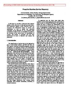
constraint solver in our architecture. As input, this component needs context information which is typically distributed in the system on different levels. In S MART S OFT we use an event based mechanism to acquire certain information from skill components. For instance, for both models it is necessary to get the battery value. Thereto the constraint solver component directly subscribes to the base component to be informed if the battery value drops below a certain threshold. More advanced data acquisition mechanisms (e.g., those needed to collect information to deduce the waiting time in front of a coffee machine) can be implemented based on a data aggregation approach like in [7]. Finally, some context information is related to the current environment model of the robot, that is stored and updated in the knowledge base of the sequencer (see top right in fig. 3). As the sequencer is always the master in our system it has to provide the relevant information to the constraint solver. For example the context variable ctx maxAllowedVelocity in list. 2 is stored in the knowledge base, because it relates to the current physical limits of the robot, the current situation, etc. The next question relates to the triggering of the adaptation mechanism. In our system we separate the triggering (execution) of the constraint solver from its model implementation. This enables the VML modeller to focus on adaptation without having to care about the execution environment. There are two possible situations where the constraint solver is triggered to calculate new values for certain variation points. In the first situation the sequencer queries the constraint solver – providing current context information in the query request – for a decision to e.g., expand the current node in its task-net (see fig. 3 (c)). In this case the sequencer triggers the calculation in the constraint solver and waits for the (query) result. In the second situation a variation point (e.g., the speakerVolume in listing 3) is sporadically updated on demand each time the constraint solver receives an event about changes in relevant context variables. Again, using the event mechanism here considerably reduces communication and calculation overhead in the system. The speakerVolume variation point can be directly parametrized in the speech output component, because it typically has no effect on the sequencer. As mentioned above, other variation points like the currently suggested speed reduction must be additionally propagated to the sequencer in order to guarantee a consistent world model in the knowledge base. Figure 4 illustrates the behavior of our robot Kate according to the VML model in listing 2. Thereby, our robot Kate navigates in our home environment and decides, for each order on demand, which coffee machine to use. For this purpose, Kate balances between conflicting optimization strategies like minimizing resource consumption while keeping high the task efficiency. Figure 5 shows the evolution of the variation point maximum allowed velocity by balancing performance and energyConsumption according to the current battery level. While the battery level is higher than 30% the selected maximum velocity remains at 600 mm/s, since
500
400
300
200
100
0
10
20
30
40
50 60 BATTERY LEVEL (%)
70
80
90
100
Fig. 5. Evolution of maximum allowed velocity according to the current battery level. Results after running the VML Model in listing 3.
performance has priority over energyConsumption. However, if the battery falls below 30%, energyConsumption becomes increasingly important, therefore the selected maximum velocity decreases exponentially until reaching the minimum of 100 mm/s. V. R ELATED W ORK A. Variability in Robotics In the last decade, the robotics community has spent a lot of efforts to improve the robotics software development process in order to cope with its inherent and growing complexity and to improve its reusability, interoperability and maintainability. Many of these efforts have adopted Software Engineering best practices like those promoted by CBSE and MDE. As a result, a new set of robotics frameworks and architecture models, aimed to improve robotics software design, have been developed, like RT-Component [8], ROS [9], S MART S OFT [2], etc. Although all these approaches are already valuable steps towards building impressive systems, we believe, that improving only the development process at design-time in isolation is insufficient, and it is rather necessary to take run-time aspects like situation- and resource-awareness into account from the very beginning. One step to solve this problem is done by introducing mechanisms to model robot tasks independently of the reactive components, e.g., addressed by SMACH [1] and S MART TCL [3], [10]. The latter approach additionally allows to easily model dynamic task trees, that
are rearranged on demand according to current situation and other parameters like resource consumption or adaptation suggestions (see sec. III). Thus, one of the results in this paper is to explicate properties which are necessary to be expressed at design-time by a developer and which can be later processed on the robot at run-time. In a robotic system, variability can be identified on different levels. State-of-the-art systems focus mostly on functional variability like in [11] (based on feature models for components). By contrast, our approach is not limited to design-time variability. Instead, we introduce a DSL tailored to express variation points at design-time and their binding according to non-functional properties at run-time. DiaSpec [12] is a recently introduced Java based design language to model robotic systems on the skill layer. In addition thereto, our approach includes the sequencing layer and is more focused on variability modeling. The software community introduced the term architecturebased adaptation in a series of papers like [13] and [14] for robotic systems based on CBSE. In there, components are replaced or migrated at run-time (e.g., due to a failure or resource insufficiency) by similar components with differently implemented services. From the robotics perspective we highly support this progress. However, in contrast, the focus in our work is more on the challenge to balance between reduction of complexity at design-time and at the same time introducing models to express variability for non-functional properties which can be efficiently exploited at run-time. Thereby, we use sophisticated real-world scenarios from service-robotics to demonstrate the applicability of our approaches in robotic systems of realistic complexity. B. Expressing run-time variability in Software Engineering Numerous research works in software engineering have investigated how to model the adaptation logic [15]. Therefore, we can find a wide range of approaches that address, among others, different representations and formalisms, different levels of abstraction, different application domains, and different techniques to capture and express adaptation. Regarding approaches using different representation for expressing adaptation, in the area of software architecture, we can find Architectural Description Languages (ADL) [16] based on graphs, process algebras, and other formalisms to describe desired component configurations and specify how configurations may be changed at run-time in terms of addition and removal of components. In contrast, in the area of Dynamic Software Product Lines [17], [18], the system variability is modelled using variation points defined with a number of alternatives and constraints among them. Concerning the level of abstraction, while [17] provides designers with a high level modeling language to specify the global adaptation of the system using fuzzy logic and qualified variables (e.g., the QoS properties used to decide adaptation are expressed as enumerators defined with values like HIGH, MEDIUM or LOW), [19] allows a wide range of data types and utility functions to specify QoS properties in the components of
the system. Moreover, although most of the approaches are independent of the application domain, some are focused, e.g., on the dynamic adaptation of Graphical User Interfaces using model transformations [20], or in the use of feature diagrams to describe the functional variability of Smart Houses [18]. Finally, a number of techniques have been proposed in the literature to capture and express adaptation logic. First, most existing approaches are based on using ECA (event-condition-action) rules [20], [18], [21]. In these approaches the context and the configurations are related by a set of rules, which express how the changes of the system context should affect the running configuration of the application. ECA rules are clear and easy to write but fully specifying an adaptive system using ECA rules often requires defining a large set of rules [17]. In addition, it is not easy to check whether the full set of rules is consistent or not at design-time and it might be the case that some rules conflict with others, in particular when some changes in the context might trigger several rules. Another common way to express the adaptation logic is to define goals that the system should reach [19]. The designer establishes QoS properties and specifies the impact on them depending on the selected configuration, e.g., through utility functions. At run-time, the system should find the best configuration i.e., the one that optimizes the properties considering the current context. Goals allow to specify the adaptation logic at a higher level of abstraction than ECA rules. However, multi-dimensional optimization algorithms are usually resource and/or timeconsuming. Some approaches, like the one presented in [17], adopt a combined approach based on the use of both ruleand optimization-based mechanisms, to try exploiting their respective advantages while limiting their drawbacks. Our approach is close to the one presented in [17] but, in contrast, we do not rely on fuzzy logic to capture and describe how systems should adapt. Conversely, we offer a more precise and less limited way to describe variability, e.g., using mathematical expressions that incorporate any number of real variables. This provides designers with a more natural way for describing the variability of their systems, in particular in some application domains like in robotics. Our proposal is also close to the one presented in [19], although it relies on component-based system adaptation while ours is independent of the system organization (variation points can be components, algorithms, parameters, etc.). Therefore, the proposed modeling language can describe variability at different levels of abstraction. Although we focus on the robotic domain, all the concepts included in our approach are application independent like [17], [19] or [21]. Finally, as in [17], we have considered ECA rules and optimization of goals, but with some improvements like unit specification and normalization. VI. C ONCLUSIONS AND F UTURE W ORK In this paper we showed how to express variability in a robotic system for non-functional properties (like safety or task efficiency), using a first version of a new DSL called VML. This language enables designers to focus on
modeling the adaptation strategies without having to foresee and explicitly deal with all the potential situations that may arise in real-world and open-ended environments. The variability, purposefully left open by the designers in the VML models, is then fixed by the robot at run-time according to its current tasks and context (separation of roles and concerns). Furthermore, we underpinned the applicability of our approach by integrating it into our overall robotic architecture and by implementing it in a sophisticated real-world scenario on our service robot Kate. Thereto the VML models were translated into a constraint modeling language (MiniZinc), which is executed in a constraint solver interacting with the sequencing layer on the robot at run-time. Considering that a VML model represents a constrained optimization problem, the question arises why VML is used instead of a modeling language for constraint programming. This discussion resembles the traditional dispute between Domain-Specific Languages (DSLs) and General-Purpose Languages (GPLs). VML has the well-known advantages of DSLs (e.g., allowing solutions to be expressed at the level of abstraction of the problem domain considerably simplifying the work of the designers) and disadvantages (e.g., cost of designing, implementing and maintaining a new language) [22]. However, we highlight that the proposed language is of value because: (i) it enables designers to clearly express an important issue, i.e., the run-time variability for optimizing the execution quality of the system; (ii) it delimits the concepts and their semantics which facilitates the validation of the models; (iii) it abstracts some details such as the normalization of the formulas; and (iv) it can be extended adding new concepts and capabilities not supported by the expressiveness of the constraint modeling languages. As a conclusion, we were able to combine efforts from the different communities (SE, MDE and Robotics) in order to apply state-of-the art approaches for variability management on a robot operating in a home-like environment. For the future, we plan to extend VML with some additional syntax constructs and to improve the supporting tools, in particular the VML model editor, to provide designers with some advanced model validation and simulation facilities. VII. ACKNOWLEDGMENTS This collaboration is jointly funded by the German Academic Exchange Service (DAAD; Project ID: 54365646; Project leader: Prof. Schlegel; http://www.zafh-servicerobotik.de) and the General Directorate of International Projects of the Spanish Ministry of Economy and Competitiveness (MINECO; Project leader: Dr. Vicente-Chicote; Project ID: PRI-AIBDE-2011-1094). Juan F. Ingl´es-Romero thanks Fundaci´on S´eneca-CARM for a research grant (Exp. 15561/FPI/10). The authors also want to thank Matthias Lutz for his extraordinary support in integrating the examples on the service robot Kate.
R EFERENCES [1] J. Boren and S. Cousins, “The SMACH High-Level Executive,” IEEE Robotics Automation Magazine, vol. 17, no. 4, pp. 18 –20, Dec. 2010. [2] C. Schlegel, A. Steck, D. Brugali, and A. Knoll, “Design abstraction and processes in robotics: From code-driven to model-driven engineering,” in Simulation, Modeling, and Programming for Autonomous Robots, N. Ando, S. Balakirsky, T. Hemker, M. Reggiani, and O. Stryk, Eds. Springer Berlin / Heidelberg, 2010, vol. 6472, pp. 324–335.
[3] A. Steck and C. Schlegel, “Managing execution variants in task coordination by exploiting design-time models at run-time,” in IEEE/RSJ International Conference on Intelligent Robots and Systems (IROS), San Francisco, California, USA, Sept. 2011, pp. 2064 –2069. [4] N. Nethercote, P. J. Stuckey, R. Becket, S. Brand, G. J. Duck, and G. Tack, “MiniZinc: Towards a standard CP modelling language,” in Proc. of 13th International Conference on Principles and Practice of Constraint Programming. Springer, 2007, pp. 529–543. [5] R. C. Gronback, Eclipse Modeling Project: A Domain-Specific Language (DSL) Toolkit. Upper Saddle River, NJ: Addison-Wesley, 2009. [6] C. Schlegel, “Fast local obstacle avoidance under kinematic and dynamic constraints for a mobile robot,” in IEEE/RSJ International Conference on Intelligent Robots and Systems (IROS), Victoria, Canada, Oct. 1998. [7] A. Lotz, A. Steck, and C. Schlegel, “Runtime Monitoring of Robotics Software Components: Increasing Robustness of Service Robotic Systems,” in 15th International Conference on Advanced Robotics (ICAR), Tallinn, Estonia, June 2011. [8] N. Ando, T. Suehiro, K. Kitagaki, T. Kotoku, and W.-K. Yoon, “Rtcomponent object model in rt-middleware distributed component middleware for rt (robot technology),” in IEEE International Symposium on Computational Intelligence in Robotics and Automation (CIRA ’05), June 2005, pp. 457 –462. [9] M. Quigley, B. Gerkey, K. Conley, J. Faust, T. Foote, J. Leibs, E. Berger, R. Wheeler, and A. Ng, “ROS: an open-source Robot Operating System,” ICRA Workshop on Open Source Software, 2009. [10] A. Steck, A. Lotz, and C. Schlegel, “Model-driven engineering and run-time model-usage in service robotics,” in Proceedings of the 10th ACM International Conference on Generative Programming and Component Engineering (GPCE), Portland, Oregon, USA, Oct. 2011. [11] L. Gherardi and D. Brugali, “An eclipse-based feature models toolchain,” in 6th Workshop of the Italian Eclipse Community (EclipseIT 2011), Milano, Italy, June 2011. [12] D. Cassou, S. Stinckwich, and P. Koch, “Using the diaspec design language and compiler to develop robotics systems,” DSLRob, 2011. [13] J. C. Georgas and R. N. Taylor, “Policy-based self-adaptive architectures: a feasibility study in the robotics domain,” in Proceedings of the 2008 international workshop on Software engineering for adaptive and self-managing systems, ser. SEAMS, Leipzig, Germany, May 2008. [14] G. Edwards, J. Garcia, H. Tajalli, D. Popescu, N. Medvidovic, G. Sukhatme, and B. Petrus, “Architecture-driven self-adaptation and self-management in robotics systems,” in International Workshop on Software Engineering for Adaptive and Self-Managing Systems (SEAMS), Vancouver, BC, Canada, May 2009, pp. 142–151. [15] M. Salehie and L. Tahvildari, “Self-adaptive software: Landscape and research challenges,” ACM Transactions on Autonomous and Adaptive Systems, vol. 4, no. 2, pp. 14:1–14:42, May 2009. [16] J. S. Bradbury, J. R. Cordy, J. Dingel, and M. Wermelinger, “A survey of self-management in dynamic software architecture specifications,” in Proceedings of the 1st ACM Workshop on Self-managed systems (SIGSOFT), Newport Beach, California, Oct. 2004. [17] F. Fleurey and A. Solberg, “A domain specific modeling language supporting specification, simulation and execution of dynamic adaptive systems,” in Proceedings of the 12th International Conference on Model Driven Engineering Languages and Systems (MODELS), Denver, CO, USA, Oct. 2009, pp. 606–621. [18] C. Cetina, P. Giner, J. Fons, and V. Pelechano, “Using feature models for developing self-configuring smart homes,” in Proceedings of the Fifth International Conference on Autonomic and Autonomous Systems (ICAS), Valencia, Spain, Apr. 2009, pp. 179–188. [19] S. Hallsteinsen, E. Stav, A. Solberg, and J. Floch, “Using product line techniques to build adaptive systems,” in 10th International Conference on Software Product Line Conference (SPLC), Baltimore, Maryland, USA, Aug. 2006. [20] J. Criado, D. Rodrguez, L. Iribarne, N. Padilla, and C. Vicente-Chicote, “Composing Model Transformations at Runtime: an Approach for Adapting Component-Based User Interfaces,” in 7th Int’l Conf. on Software Paradigm Trends (ICSOFT), Rome (Italy), July 2012. [21] M. Hussein, J. Han, and A. Colman, “An approach to model-based development of context-aware adaptive systems,” in IEEE 35th Annual Computer Software and Applications Conference (COMPSAC), Munich, Germany, July 2011, pp. 205 –214. [22] M. Mernik, J. Heering, and A. M. Sloane, “When and how to develop domain-specific languages,” in ACM Computing Surveys (CSUR), vol. 37, no. 4, Dec. 2005, pp. 316–344.