May 25, 2005 - At design-time a model of the managed system is created. .... hosting the services and the XML configurations describing the low-level ...
Id: udo-indin05.doc 2005-05-25 17:02:48Z krumm
Automated Runtime Management of Embedded Service Systems Based on Design-Time Modeling and Model Transformation Stefan Illner, Andre Pohl and Heiko Krumm
Ingo Lück, Darius Manka and Thomas Sparenberg
FB Informatik, Universität Dortmund 44221 Dortmund, Germany e-mail: {stefan.illner, andre.pohl, heiko.krumm}@udo.edu
Materna Information & Communications 44141 Dortmund, Germany e-mail: {ilueck, dmanka, tsparenb}@materna.de
Abstract — The management of distributed and embedded service systems is a complex task as the services are exposed to changing environments which have to be reflected by the services’ configurations. These configurations are commonly based on abstract management policies. Embedded devices usually lack the resources to perform the necessary computations to derive an actual configuration from an abstract policy. Thus we developed a two phase management approach that splits up the management process into a design-time and a runtime task. At design-time a model of the managed system is created. This model is augmented by high-level, environmentaware management policies that are automatically refined to low-level service configurations using graph-transformation techniques. This phase is based on the concepts of model-based management and on parts of the Generalized Role Based Access Control model to handle the modeling of the environmentaware policies. The runtime phase covers the enforcement of the environment-aware management policies by a set of management services responsible for the setting of suitable service configurations. Index Terms — model-based management, automatic & adaptive management, embedded service systems
I. INTRODUCTION The automotive, industrial, home, and telecommunication domains perceive an increasing demand for embedded real-time applications which rely on cooperating networked devices. A plethora of devices is arising covering small and specialized devices with restricted computing power as well as well-equipped servers and workstations. Stationary and mobile devices cooperate in dynamically varying associations and utilize a wide variety of supporting services. Mobility, changing tasks, as well as fluctuating supportive service costs and availabilities demand that the frequently needed adaptations of application configurations are accomplished by automated application management functions. The work presented in this paper is part of the ITEA SIRENA [1] project, which has the goal to develop a universal service infrastructure for real-time, networked and embedded devices, which can be utilized in the industrial, home, telecommunication and automotive domain. Our work focuses on the automated adaptation and reconfiguration of services in reaction to changes in the environment. As embedded systems are addressed, the time spent for necessary configuration changes on the devices should be low, so no expensive computations can be done to accomplish this.
Our approach to solve this problem is to divide the adaptation process in two parts. At design time, a model of the managed system is generated and configurations for the services are created. At runtime, configuration changes confine to selecting and activating a suitable configuration. The enforcement of management policies is done by a separate management process at system runtime. The design time task, the creation of appropriate environment related service configurations, is supported by a graphical modeling tool which allows the automated derivation of low-level configurations from high-level policies. The outline of the paper is as follows. First, we introduce the concept of model-based management. The elements which are used in modeling are explained in more detail in section III. The automated generation of policy elements by means of graph transformation techniques is subject of section IV. The details of how the overall policy is enforced at runtime are given in section V. II. MODEL BASED MANAGEMENT The model-based management approach utilizes an object-oriented model of the managed system to ease the creation and modeling of complex management policies. The graph-based modeling of a system is supported by a graphical modeling tool. Common policy-based management approaches [2] apply low level policies to describe management demands. Systems created using the model-based approach ([3], [4]) use much more abstract high-level policies to describe the desired behavior, from which concrete service configurations are automatically created. Basically a model is build up of some common and application domain specific model nodes like Service or Device and edges connecting these nodes. Each connection between two nodes expresses a specific dependency or relationship between these nodes. In common the model is divided into different abstraction layers ranging from a very abstract enterprise view, including the high-level policies to be enforced, to low-level system elements like specific hosts, devices, and network protocol stacks. This approach was successfully applied for the creation of firewall [4], VPN [5] and Kerberos V configurations.
1
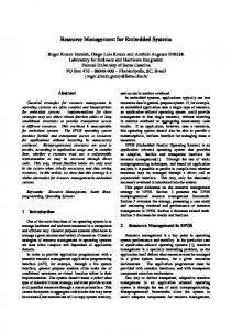
Fig. 1: Overall model structure
Model Structure The OSI FCAPS framework defines five different areas of management: Fault-, Configuration-, Accounting-, Performance-, and Security-Management. Previously the model-based management approach was mainly applied for the area of Security-Management. In the scope of the SIRENA project the other areas of management move into the focus. Moreover the creation of environment aware policies and the tighter connection to the area of service oriented architectures require the re-organization of the main model structure. This new model structure is outlined in Fig. 1. The model contains three abstraction layers, namely the “Roles & Goals” layer which contains the most abstract enterprise view, the “Services & Configurations” layer which deals with the services and abstract configuration relations between the services and last the less abstract “Devices & Files” layer containing the hardware devices, which are hosting the services and the XML configurations describing the low-level management policies in form of service configuration-descriptions. The vertical adjustment divides the model into the System, Control, Policy, and the new Environment sections. The System section contains all model elements which represent parts of the managed system e.g. application services like a file- or mail-server, including the hosting hardware and devices. The Control section contains nothing on the upper layer, as the policy enforcing components are not visible above the “Services & Configurations” layer. The lower two abstraction layers contain the required policy enforcement services such as the Management Infrastructure Services and devices which host these services. Management goals are modeled using specific policy objects. These are arranged in the Policy section of the model and are refined in the lower layers. The most right column contains the objects required to model the environmental awareness of given management policies. III. MANAGEMENT M ODEL ELEMENTS Management models are created for a specific application domain, where the components are well known, as well as the possible relations (connections) between them. These elements and the information about their connectivity are subsumed in a so called meta-model. For every node type,
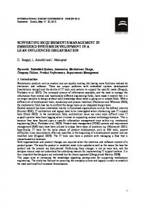
Fig. 2: System, Control Services and Management Goals
the meta-model contains information to which other node connections are allowed, and with which cardinality. With this information, the correctness of the syntax of the model can be ensured during the model creation process, by checking the constraints each time a new edge is inserted. Moreover each node may contain additional properties which conform to the properties of the represented real world object. In Fig. 2, one can see a snapshot of a simplified example model, showing the System, Policy and a compressed Control section. In the following the basic elements are introduced by means of this example. An Attribute Set element is used to group attributes of services. These groups are used by Management Goals to model specific requirements. In Fig. 2 the element named Normal Monitoring represents such an Attribute Set. It is connected to a single Service Attribute and one Service element. The former connection models that only the “Open Files” attribute, which contains the number of concurrently opened files, is part of the set. The latter connection states, that all attributes, namely the “Max Size” and the “Store Policy” attributes of this service are part of the Attribute Set. Management Goal elements are used to express specific targets of a management policy. The types of Management Goals are centered around the FCAPS areas of common management. Thus these elements may address goals regarding e.g. the fault, performance or security management areas. In the depicted example two goals are defined: the Monitoring goal defines a specific monitoring policy and the Load Management goal defines some mandatory configuration tasks in case that the File Service is about to exceed its storage space capacities. The Load Management goal is connected to a so called Actual Configuration Chain which contains the actual reconfiguration information. When dealing with reconfiguration of services by setting specific service attributes to new values there have to be some elements that are able to express such new value settings. Moreover in a reconfiguration phase the managed service may have to be restarted to activate the new con-
2
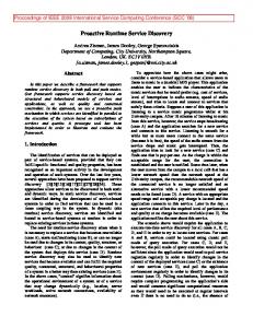
Fig. 3: Control Services, Management Goals, Profiles and derived Configuration elements
figuration settings, so the service’s life cycle management is also in charge. The model element which deals with these issues is named an Actual Configuration Chain (cf. Fig. 2, right side). This element is built up of two other model elements, an Actual Value and a Lifecycle Management Command, which are connected by directed edges to enable the modeling of precedence of configuration settings. The Actual Value element itself is connected to the Service Attribute which should be set to the actual value. The Life Cycle Management Command element is connected to the service for which it should be invoked. In the example the Actual Configuration Chain contains reconfiguration tasks for the File- and Mail Service. The Mail Service’s attribute “Max Size” for the definition of the maximum size of an accepted incoming E-mail is set to the value of 500 kilobytes. After that the value of the “Store Policy” attribute is set to “cache” which means that the received E-mail should be cached locally and should not be saved using the existing File Service. After setting these two attributes a “Restart” Life Cycle Management Command is issued to activate the new configuration. Finally the File Service is put into a Read-Only mode by setting the attribute “Read Only” to “true”. Without the possibility of modeling configuration precedence the reconfiguration may have led to errors in the Mail Service as it might have tried to write to a read-only file system if the File Service would have been reconfigured already. Another model element is the Service element which represents a real world (SIRENA) service. It is characterized by its name and the attributes and operations it provides. In the example there are two services, a File Service and a Mail Service which both have two defined attributes that may be used for monitoring and reconfiguration issues. For readability reasons the service operations are omitted. Dependencies between services are modeled using directed edges. In the example above the Mail Service depends on the File Service as this is used to store the maildata. A Device is a model representation of a physical re-
source, hosting a service. In the example there are two devices, which host the File- and Mail-Services and an additional device that hosts the services of the Runtime Management Infrastructure. The communication links between devices are modeled using the Link element. A Link is a representative for any arbitrary network connection. In Fig. 3 you can see the right side of the model, also including parts of the policy and control section. The model described so far includes no information regarding the environmental state of the modeled system. This state information is now added by the introduction of Profiles. A Profile defines a specific environmental state, e.g. Working Hours or a specific fault state like Power Fault. The environmental state itself is defined using a logical expression over the activation state of so called Environment Roles. The notion of an Environment Role is adopted from the Generalized Role Based Access Control (GRBAC) model [6], an extension of the well known Role Based Access Control model [7]. In original GRBAC the environmental information was used to compute environment related access control decisions. We apply this scheme to model the environmental awareness of management policies. An Environment Role is defined by a logical expression e.g. a role named Weekend is defined like (Sat ∨ Sun). At runtime this expression is evaluated by a special Environment Role Activation Service (cf. section V). If the expression evaluates to true the role is considered to be active. Supplied with a set of different types of Environment Roles one can easily model special system states by combining these roles using logical operators (e.g. ∧, ∨ or ¬). The elements introduced to this point have to be modeled by hand; the last two elements described herein are created automatically by the modeling tool based on the information supplied by the model. The details of this derivation process are outlined in the next section. The first item that is generated automatically is the Configuration Set. This element contains less abstract information about the configurations to be enforced in certain situations and about the affected services including managed as well as management services. From the information gathered by the automatic derivation of the Configuration Set elements, from the information about the devices by which the services of the managed domain are hosted, and from the underlying network infrastructure specific XML Configuration File elements are created. These elements are directly related to real XML service configuration-descriptions which can be deployed on the Runtime Management Infrastructure. Besides using the above outlined approach for the modeling of common management policies we also apply it for modeling security policies as we already presented in [8] and [9]. IV. MODEL TRANSFORMATION After modeling the system and the abstract policy elements, the concrete configurations for the management ser-
3
Fig. 4: Application of a rule to a model
vices are generated automatically. There are two different ways to conduct this automatic generation. Either, a meta-model contains transformation methods which describe the relevant graph structures to look for and the alteration function which should be applied to the graph in case that such a structure is found. The disadvantage of this approach is that these methods are hard-coded into the meta-model and a user may not simply extend or alter the functionality of the given methods. The other approach is the graph transformation approach [10] which we have chosen for our modeling tool. The idea of this is as follows: As stated above, the model is described by a graph. Therefore it is possible to define a graph transformation system consisting of single transformation rules which alter the graph in a specified way. One such rule consists of a left-hand side L and a right-hand side R, and on detection of a L in the model, this occurrence is replaced with an instance of R. L and R are graphs also, consisting of elements of the same meta-model as the model graph does. The rule elements can be specified using the tool in the same way the model is specified. So this approach fits very well in the concept of model-based management and users are given the ability to easily extend the transformation systems provided by the meta-model. After having modeled both sides of a rule, some nodes in L are identified with nodes in R, while others are not. The same applies to the edges in L and R. The algorithm to apply a rule r to a model graph M is roughly outlined by the following sequence: 1) Find an occurrence of L in M 2) Remove all components in M which occur in L, but do not have an identity component in R 3) Insert all components into M which occur in R, but do not have an identity component in L The application of a rule r transforms the graph G to a Graph G', denoted by G ⇒ G ' . This is called a direct derivation, and G' is directly derived from G. For a better control over the application of a rule, every rule can be augmented with two additional components. A condition allows to specify certain constraints which must
be met by the detected sub graph L’ in order to match the defined pattern in the search. These constraints can refer to all attribute values of elements in L’. An effect function is a function which is applied to the inserted graph elements, and describes how the attribute values of the inserted elements are computed from the attributes of the elements of L’. The meta-model classes are designed in an objectoriented manner. If inheritance is used in the meta-model, by using either base classes or derived classes in a rule, this rule can be made more general or more specific, as needed. The first step also introduces non-determinism into the transformation process, because a left-hand pattern may match multiple times in the given model graph. Therefore the resulting graph may depend on the order in which the occurrences are found. The automated, repeated application of a rule holds the risk of infinite recursion. Just imagine the case where L consists of one node nL, and in R this node has an identity node nR, plus one more node mR. After the application of the rule, the node still remains in the model, and so this rules remains applicable. To circumvent this recursion, we use inhibiting graph components. An inhibiting component can only be part of a left hand graph L. Considering the use of inhibiting graph components, Step 1 of the transformation algorithm becomes: 1') Find an occurrence of the non-inhibiting elements of L in G and make sure that the inhibiting elements of L do not appear in G the same way In the example above, to prevent recursion, one would introduce an identity node mL for mR in L and give it the inhibiting state. After the first direct derivation, 1') will not find any more valid occurrences of L, and terminates. Applying a rule r to a Graph G several times will result in a sequence G ⇒ G1 ⇒ L ⇒ Gn . The result of several rule applications is called derivation, and Gn is derived from G. Usually, there will not be a single rule r, but a set P of rules r1 ,K , rn , where each rule serves a specific purpose. The set P is called a graph transformation system. Systems can lead to another kind of non-determinism: There may be several rules r for which Lr is identified in G, with all associated conditions fulfilled. The resulting graph G' depends on the rule chosen for transformation. If the order of precedence does matter, rules can be assigned a priority. For the example model given in figures 2 and 3, the application of a simple rule is depicted in Fig. 4. The left-hand side of the rule describes the situation that a Configuration Set exists, covering a specific attribute of a specific service, but no XML Configuration File exists which carries the configuration information for this service. The absence of this file is expressed by inserting this file with its connections into the left-hand side of the rule, but then setting these elements inhibiting, which is visually expressed by the dashed lines in Fig. 4a. In such a case, we know that there must be an XML configuration file inserted into the model, which is expressed by the right-hand side of the rule. The newly introduced elements appear with a bold border.
4
In our management model, the following two rules are the most important ones from the transformation system: • Every Management Goal must have exactly one associated Configuration Set. • For each service which can be reached via one of the paths ‘Configuration Set – Goal – Attribute Set – Attribute – Service’ or ‘Configuration Set – Goal – Configuration Value Chain – Attribute – Service’, a Configuration Set must be associated to XML Configurations. After the automated generation of the attributes, the user can intervene and alter some values, if the necessity should arise. The graph transformation also has another valuable benefit for model checking. It is possible to specify certain graph patterns that are allowed for the left-hand side of a rule. For each pattern it is specified whether such a pattern is mandatory or forbidden. If a mandatory pattern is given, but no matching sub-graph is found in the model, the model is invalid. A model is also invalid, if any of the forbidden patterns is detected in the model graph. This allows the detection of semantic errors, which cannot be caught by the static analysis of the connection restrictions defined in the meta-model. V. RUNTIME POLICY ENFORCEMENT The policies which are created by the modeling tool are deployed onto a runtime enforcement infrastructure (cf. Fig. 5). This infrastructure contains the required services to enable the automatic and adaptive management of (embedded) service systems. The infrastructure is build up upon six services, each responsible for a special area of service management. The Fault Management Service in conjunction with the Poll- and Event-Monitor services is responsible for the monitoring of service faults and fault-events. Changes in the values of monitored service parameters and received fault events are forwarded to the Environment-Role Activation Service which uses these parameter values and events to compute the set of active environment roles. The parameters required for a computation of a role activation state are part of the role-definition which is done at design-time. Whenever a computation leads to a change in the set of active environment-roles, these changes are notified to the Automatic Adaptation/Dynamic Reconfiguration (AADR) Service. This service is responsible for the automatic adaptation to environmental situations. To accomplish this task the service looks at the set of currently active environmentroles and matches all profiles that are active with this set. If a change in the set of active profile occurs the corresponding service configurations have to be enforced. The AADR Service determines the related configuration sets and instructs the Deployment Management Service to forward the configuration changes to the Service Control Management Services which are responsible for the involved services’ control. The Service Control Management Services deploy the new configurations and may use the Service Life-Cycle Management Service to activate the new configuration by
Fig. 5: Runtime service infrastructure
restarting the involved services if necessary. VI. RELATED WORK Chisel [11] proposes a context-aware, policy-driven framework for adaptation of services. In this approach, the services will be adapted to use different behaviors, driven by a human-readable declarative adaptation policy script. Furthermore, the chisel framework allows to make mobileaware dynamic changes to the behavior of various middleware-services, and it provides the addition of new unanticipated behaviors at run-time, without changing the middleware or the application using it. Similarly, Lymberopoulos et al. [12] investigate dynamic adaptation of policies in response to changes within the managed environment. Here, policy adaptation includes both dynamically changing policy parameters and reconfiguring the policy objects. The proposed framework is primarily used to provide dynamic management of services in Differentiated Services (DiffServ) networks. VII. OUTLOOK Currently we are implementing the described metamodel for specific SIRENA demonstrators from the home, automotive and industrial domains to demonstrate the applicability of our approach. To ease the creation of further models, basic model elements have been developed which are used as a basis for the implementation of the domain specific models. The modeling of management policies is supported by our management tool which allows the graphical modeling based on arbitrary meta-models. This tool is subject to ongoing development addressing the integration of supporting modeling features like visualization techniques and the so called Semantic Zooming that ease the handling of very large models. The presented graph transformation algorithm is part of our graphical modeling tool. This algorithm currently allows the matching of graphically modeled graph patterns,
5
including the refinement of a matching by accessing and using low level graph-element properties for left- and righthand patterns. The integration of graph grammars which include the specification of complex regular expressions may be an interesting extension to the existing algorithm and to currently used modeling principles. The services that are responsible for the runtime enforcement of the modeled management policies have been specified and are currently implemented. VIII. CONCLUDING REMARKS The approach presented in this paper applies a two-phase management approach split into the design-time task of modeling, analysis and automatic refinement of environment-aware management policies and the runtime enforcement of these policies. The creation of models relies on so called meta-models that deal with the particularities of the addressed management domain. Here we presented a basic model that may be used as a basis for the creation of domain specific meta-models and includes all required base functionality to model the environment-aware management policies. Moreover we presented a graph-transformation based approach for the automatic refinement of modeled policies. The distinction between design-time and runtime tasks leverages the full power of model-based management on the one hand, while still ensuring that application of this method also provides adaptive management for small, embedded devices which do not offer enough computing power to. The work described herein was funded by the German Federal Ministry of Education and Research (BMBF) within the ITEA-SIRENA project (01ISC09G).
IX. REFERENCES [1]
SIRENA: Service Infrastructure for Real time Embedded Networked Applications, Project in the European Framework ITEA, see URL: http://www.sirena-itea.org (2003-2005). [2] M. Sloman, “Policy Driven Management for Distributed Systems”, Journal of Network and Systems Management, Vol. 2, No. 4, 1994. [3] P. Herrmann and H. Krumm, “Object-Oriented Security Analysis and Modeling”, in Proceedings of the 9th Int. Conference on Telecommunication Systems, pages 21-32, ATSMA, IFIP, 2001. [4] I. Lück, C. Schäfer, and H. Krumm, “Model-based Tool-Assistance for Packet-Filter Design”, in: M. Sloman, E. Lupu, J. Lobo (Eds.), Policy 2001, LNCS 1995, pp. 120-136, Springer-Verlag, 2001. [5] I. Lück, S. Vögel, and H. Krumm, “Model-based configuration of VPNs”, in R. Stadtler, M. Ulema (eds.): Proc. 8th IEEE/IFIP Symposium NOMS 2002, IEEE, pages 589-602, 2002. [6] M. J. Moyer and M. Ahamad, “Generalized Role-Based Access Control”, in: IEEE Proceedings of the 21st International Conference on Distributed Systems, Mesa, April 2001. [7] D. Ferraiolo and R. Kuhn, “Role Based Access Control”, in: Proceedings of the 15th National Computer Science Conference, 1992. [8] Stefan Illner, Andre Pohl, and Heiko Krumm, “Security Service Adaptation for Embedded Service Systems in Changing Environments”, in Proc. of the 2nd Int. Conf. on Industrial Informatics (INDIN’04), 2004, 457-462. [9] Stefan Illner, Heiko Krumm, Andre Pohl, Ingo Lück, Darius Manka, and Thomas Sparenberg, “Policy Controlled Automated Management of Distributed and Embedded Service Systems”, in Proc. of the IASTED Int. Conf. on Parallel and Distributed Computing and Networks (PDCN), 2005, 710-715. [10] M. Andries et. al., “Graph Transformation for Specification and Programming”, Science of Computer Programming, Vol. 34, 1999. [11] J. Keeney and V. Cahill, “Chisel: A Policy-Driven, Context-Aware, Dynamic Adaptation Framework”, Fourth IEEE International Workshop on Policies for Distributed Systems and Networks (POLICY 2003), Lake Como, Italy, 2003. [12] L. Lymberopoulos, E. Lupu and M. Sloman, “An Adaptive PolicyBased Framework for Network Services Management”, Journal of Network and Systems Management, 11(27), 2003.
6