Decentralized Active Gate Control for Current Balancing of Parallel
Recommend Documents
methods for a high power (600 kVA) parallel connected ... the proposed method is also confirmed by experimental .... Figure 1: Circuit of direct-drive permanent-magnet synchronous generator (PMSG) wind turbine system .... Resistor of LCL.
Sustainable Distributed Generation and Renewable Energy Group. 1 Department of Automatic Control Systems & Computer Engineering. 2 Department of ...
Decentralized Control for Parallel Operation of Distributed Generation ... Comte d'Urgell 187. ... controller for islanding parallel inverters in an ac-distributed.
the cost sustained to reach its destination by a proper flow assignment. Practically speaking, a single packet of the flow could be approximately considered as an ...
Jan 5, 2000 - switching state sequences known for a single system and are comparatively evaluated ... alized at the Vienna University of Technology. In order.
Apr 4, 2016 - Decentralized voltage control of clustered active distribution network by means of energy storage systems. M. Bahramipanahâ, R. Cherkaoui, ...
Apr 4, 2016 - and control, of Distributed Energy Storage Systems (DESSs). In this respect ...... rent time t converged and the active/reactive DESSs power set.
Computational Mechanics Codes. P.K. Jimack ... School of Computer Studies ... during the parallel, adaptive solution of various computational mechanics prob- ...... there is a trade-o between the quality of the nal partition and the amount of.
The control objective is for each vehicle to maintain a constant velocity and ... straight line such that individual vehicles move at a constant desired velocity Vd ...
Dec 15, 2010 - Similarly the AWGN ni(t) with one sided PSD N0 can be written as ni(t) = nc(t) + ...... Webpage:ȱwww.eusipco2011.org. Proposals for special ...
machinery, and aircraft gas turbine engines. Vibration caused by mass ... control force to the rotor, and active balancing techniques adjust the mass distribution ...
AC-DC Interconnected Power System Through HVDC Link. Using PSO ... bEEE Deparment,KLN College of Engineering,Madurai-630611,Tamilnadu,India ...
manufacturing process, which is part of the thermal control ... predetermined test sequence [21]. ..... physical transmission costs and the protocol overhead. The.
Jul 5, 2017 - the MoS2/graphene interface and MoS2 channel conductivity leading to spin dephasing in ..... electrons in monolayer MoS2 and WS2. Nat.
Sep 3, 2013 - Search. Take our author survey for a chance to win a â¬300 / $300 .... Not logged in Google [Search Crawler] (3000811494) 66.249.66.139.
as thermal-aware task scheduling to minimize hardware DTM. (dynamic thermal management techniques such as frequency and voltage scaling) [23].
Cavity formation behind a backward- facing step ... Due to the structure of cavities, the assumption that the .... P. Batten, N. Clarke, C. Lambert, and D.M. Causon.
The octree is generated automatically and handles any type of 3-D geometry and domain connectivity. The method is evaluated in terms of execution time as.
branch-and-bound algorithm as well as different load balancing strate- gies. The results are very ... ysis using a Geographic Information System (GIS) and net-.
Three-Phase Shunt Active Power Filters. Quoc-Nam Trinh and ... justable speed drives, electric arc welders, and switching power supplies causes large amounts ...
sometimes during discharge, by connecting external loads ... recover. In fact, deep discharge may cause the cell to short- circuit, an event from which it will ... Driver. C h a rg e r. Figure 2. Example of targeted equalization. .... hard to be adde
Loss Balancing SVPWM for Active NPC Converters. Xin Jing1, Jiangbiao He2, Nabeel A. O. Demerdash2. 1Global Vehicle Engineering. Global Electrification ...
This paper focuses on the three-stage active gate drive technique [9] and shows how this technique can be extended to include short circuit protection in IGBTs.
log n;O ?m n using r rounds of communication, w.h.p.. BMS97] extends the above results to two directions. Berenbrink, Meyer ..... their parent node in the tree.
Decentralized Active Gate Control for Current Balancing of Parallel
modules can be connected in parallel or in series to provide the requested current or ... the system, as well as tolerances and delay times in the gate driving circuits, ... or the internal gate resistors RG,int as well as the internal capacitances CGe ... Alternatively, the currents can also be balanced by controlling the switching ...
Decentralized Active Gate Control for Current Balancing of Parallel Connected IGBT Modules
LOBSIGER Yanick
Decentralized Active Gate Control for Current Balancing of Parallel Connected IGBT Modules Y. Lobsiger, D. Bortis and J. W. Kolar Power Electronic Systems Laboratory, ETH Zurich Physikstrasse 3, 8092 Zurich Switzerland Phone: +41 44 632 47 94 Fax: +41 44 632 12 12 Email: [email protected] URL: http://www.pes.ee.ethz.ch
Keywords IGBT , Parallel operation , Load sharing control , Current sensor
Abstract In modern power converters operating at currents of few kA and voltages of several kV, Insulated Gate Bipolar Transistor (IGBT) modules are typically used. The increased power demand of modern inverters and rectifiers results in higher currents and voltages. Currents up to tens of kA and voltages up to tens of kV are required, which exceed the ratings of IGBT semiconductors currently available. Multiple IGBT modules can be connected in parallel or in series to provide the requested current or voltage rating. Depending on the interconnection of the switches, parameter variations in the semiconductors and in the system, as well as tolerances and delay times in the gate driving circuits, an unbalanced current or voltage distribution may occur. Therefore, the IGBT modules are generally derated, which results in an increased number of devices and volume being required. In this paper, a modular concept of a decentralized active gate control for current balancing of parallel connected IGBT modules is presented. It operates distributed to the gate drive units (GDU), the hardware and software configurations are independent of the system design and no restrictions on the number of parallel connected IGBT modules exist.
1
Introduction
The increased power demand of modern inverters and rectifiers operating at fixed system voltages of few kV results in higher currents. Values up to tens of kA are required, which exceed the ratings of IGBT semiconductors currently available. Multiple IGBT modules can be connected in parallel to provide the requested current rating. In doing so, several factors may cause dynamic and static unbalanced currents of the parallel connected IGBT modules and can evoke unwanted system failures. Substantially, these are differences in the interconnection of the switches to the busbar and heat sink, parameter variations of the semiconductors, as well as tolerances and delay times in the gate driving circuits. In Fig. 1, a schematic overview of these quantities is shown, which are explained in the following. Differences in the busbar connections lead to unequal current paths of the switches and thus to varied connection inductances Lconn and resistors Rconn [1–3]. An asymmetric system geometry leads to different thermal resistances Rth of the heat sink. Internal tolerances of IGBT and diode modules, i.e. differences in the Gate-emitter threshold voltages vGe,th and Collector-Emitter saturation voltages vCE,sat , the diode forward voltages vf , the IGBTs transconductances gm , the bonding inductances LC , LE , Le and LG,int or the internal gate resistors RG,int as well as the internal capacitances CGe and CGC , influence their switching and on-state behavior [3–6]. In addition, some of these parameters, e.g. gm , vCE,sat and vf , are temperature-dependent, which in combination with the different thermal resistances further affect the current balancing [7]. The switching and on-state behavior of an IGBT is controlled with the Gate Drive Unit (GDU), whereas the delay times tdelay and the gate currents iG , e.g. defined by the GDU’s supply
EPE 2011 - Birmingham
ISBN: 9789075815153
P.1
Decentralized Active Gate Control for Current Balancing of Parallel Connected IGBT Modules
LOBSIGER Yanick
Isolation Barrier
v+ RG,on
tdelay
C
LC G
LG
LG,int
CGC RG,int iG CGe
RG,off
gs
e
v– Gate Drive Units
BB1 Rconn,C Lconn,C
PL
gm vCE,sat
vf
TC
Rth
TA
E
Rconn,E Lconn,E
BB2
vGe,th
Le
LE
IGBTs
Interconnections
Fig. 1: Overview of the quantities responsible for the unbalanced current distribution of parallel connected IGBT modules related to the gate drive units, the IGBTs and the interconnections. iin
iA iB
+
vin
iC
–
iA1
iA2
iA3
iAn
GDU
GDU
GDU
GDU
gsA1
gsA2
gsA3
gsAn
I/Os main control unit (PWM) and active gate control
Fig. 2: Parallel connected IGBT modules as part of a converter with individual GDUs. Each gate signal (gsAi ) is controlled by a centralized active gate control unit that measures all IGBT currents to ensure a balanced current distribution.
voltages v+ and v– , the gate resistors RG,on/off and the gate wiring inductances LG , impact the current sharing substantially [8]. For that reason, the IGBT modules are generally derated, which results in an increased number of devices and volume being required. In order to achieve an even current balancing, a symmetrical thermal layout and interconnection of the IGBT modules to the busbar should be ensured. The manufacturer commonly preselects the IGBT modules depending on the above mentioned parameters of the semiconductors [9]. For static current balancing and thermal stability IGBTs with a positive temperature coefficient should be used [10]. However, despite this costly classification, the maximal power rating of the IGBT modules must still be reduced. Another possibility is to insert additional components, such as series resistors or inductances, in the current paths [1]. The series resistors, however, result in additional losses and the inductances reduce the switching speed. Alternatively, the currents can also be balanced by controlling the switching and on-state behavior with the GDUs. In order to minimize delay times and costs a common GDU for all parallel connected IGBT modules can be used, if the IGBTs are matched [8, 11]. Individual gate resistors, common mode chokes or balancing cores must be used in such cases to reduce the influence of the different emitter voltages caused by the inductive coupling [8, 12]. An individual GDU is used for each IGBT module to avoid these coupling effects. In contrast to the common GDU, the delay time skews, the differences in the GDU’s supply voltages and in the gate resistors have to be minimized [11]. The propagation delays result mainly from galvanic isolators such as optocouplers, which typically show delay skews of 60 − 100 ns1 , and the output stage of the GDU, whose delay time can vary in the range of 5 − 15 ns2 . However, as proposed in previous papers [13–15], if an active gate control is applied, the inevitable delay times of the individual GDUs and the tolerances of RG,int/ext and vGe,th , resulting in different turn-on and turn-off times of the IGBTs [4], can be compensated. Thereby preselection and derating of the switching devices can be avoided. A schematic overview of a centralized active gate control is illustrated in Fig. 2. It can be seen that each current of the IGBT modules connected in parallel is measured by a central unit to detect the rising and falling edges of the current waveforms. Out of the measured delay times between the different IGBT modules, the centralized control unit (DSP / FPGA) adjusts the turnon and turn-off times of the PWM-unit for each GDU independently to ensure simultaneous switching and a dynamically-balanced current sharing, which generally also results in a statically-balanced current sharing for IGBTs with positive temperature coefficient. If needed, in addition to the switching time control, the GDUs supply voltage can be controlled to ensure a statically balanced current sharing. Usually the centralized gate control circuit is designed for a certain system configuration with a given number of IGBT modules connected in parallel, which makes subsequent modification unfeasible. Apart 1 Avogo 2 IXYS
HFBR-Series optical links, optocouplers as Optek OPI1268 IXD 430 Series
EPE 2011 - Birmingham
ISBN: 9789075815153
P.2
Decentralized Active Gate Control for Current Balancing of Parallel Connected IGBT Modules
Fig. 3: Parallel connected IGBT modules as part of a converter with individual GDUs containing DAGC. Each GDU measures the current of its IGBT and gets a reference signal (current edge and/or amplitude value) from a neighbor GDU. Therewith, it controls the switching times to ensure a balanced current distribution.
from the costly isolated current sensors and the bidirectional cabling, in addition, the number of I/Ochannels of the control unit or the maximum available calculation capacity is limited and probably can not meet the needed requirements. In this paper, a modular concept of a decentralized active gate control (DAGC) [16] consisting of independent and equal GDUs for current balancing of parallel connected IGBT modules is presented, whereby the hardware and software configurations are independent of the system design and no restrictions on the number of IGBT modules connected in parallel exist. In contrast to the centralized control circuit, each GDU measures and controls the current of its IGBT module individually. In consequence, the control for the current balancing is distributed to all GDUs and no supervising control circuit is needed. However, a communication between the GDUs is naturally needed. The main control unit is only responsible for the control of the converter, i.e. the generation of the switching signals, and works independently of the parallel connected IGBT modules. In Fig. 3 the block diagram of the DAGC is shown. In section 2, the DAGC is presented and the operating principle is explained in detail. One key component of its implementation is the current measurement including edge detection that is then investigated in section 3. The communication between GDUs, another essential integral part of the DAGC, is described in section 4. Finally, the performance of the DAGC is experimentally verified in section 5 by measurements with the developed hardware.
2 2.1
Decentralized Active Gate Control Operating principle
The DAGC [16] consists of equivalent and independent isolated GDUs, as shown in Fig. 3, where each GDU drives one IGBT. In addition to the gate drive output stage, the GDU contains mainly the same features as the centralized active gate control [13–15], i.e. a current measurement circuit and an independent digital control unit, e.g. FPGA, to control the turn-on and turn-off times as well as the switching behavior of the IGBT. The control to balance the currents of the parallel connected IGBT modules is therefore distributed to all GDUs and no supervising control circuit - as used in [13–15] or Fig. 2 - is needed. The main control unit operates independently of the parallel connected IGBT modules and the number or I/O-channels to the GDUs is reduced to just one single output signal common for all parallel connected GDUs and IGBT modules as depicted in Fig. 3. In order to control the turn-on and turn-off times of the IGBT, which in general are different for each switch, the GDUj has to measure the switching times, which could be calculated out of the time difference between the incoming PWM gate signal gsA and the current edge of iAj measured by the current sensor and an edge detection comparator. If the isolator’s delay skews of the PWM gate signal are negligible, as it is the case for isolators based on electrical transformers [17], each GDU can control the turn-on and turn-off time independently to a predefined value without the need of communication. The challenge of these transformer-based signal isolators is the high voltage isolation, that is why optical isolators or links are typically applied. The propagation delay skew for optical isolators is, as already mentioned, in the range of 60 − 100 ns neglecting aging effects. In such cases, it is insufficient to control the turn-on and turn-off times to a constant value. The control unit needs a reference signal containing information about the current imbalance between the driven and a second IGBT, e.g. the effective delay time between the two current edges or the amplitude difference after the turn-on switching transients, to adjust the switching times for balancing the currents.
Fig. 4: Simulated turn-on delay times with DAGC using the a) master-slave and b) daisy chain control structure for 4 parallel connected IGBT modules based on individual sampling-jitter of the PWM gate signal input and of the current edge detection assuming digital control units operating at the frequency of fs = 100 MHz.
Each GDU can directly provide the occurrence of its IGBT’s current edge to another GDU, for example galvanically isolated with a signal transformer, where the control unit of the GDU receiving this signal is able to calculate a reference signal out of the effective delay time between the received and the own current edge signal. In this case, the propagation delay skew of this digital signal has to be minimized. Instead of transmitting the current edges, it is also possible to transmit the current amplitude, which is measured and sampled with an ADC directly after the turn-on switching transients, as a digital value to another GDU via a serial data channel. The receiving GDU calculates the reference signal as the amplitude difference between this received digital value and the one of the own measurement. Alternatively, each GDU could also directly measure the currents of the own and another IGBT with two current sensors to derive the needed reference signal without the need of communication. As a reference either one IGBT current for all remaining GDUs (master-slave) or the IGBT current of the neighbor on the, e.g., left hand side (daisy chain) can be used. In the next subsections, these two control structures are analyzed and compared.
2.2
Master-slave control structure
In the master-slave control structure one GDU is selected as master and it provides to all other GDUs (slaves) the information needed for their reference signal calculation. Fast control dynamics and small temporary total switching time differences for all GDUs can be achieved with this topology because of the common reference for all slaves. As the minimum temporal resolution is given by the operating frequency fs of the digital control units, the slave GDUs can be synchronized on average to the master GDUs independently of each other within an interval of Ts = 1/fs . Due to the individual clocks and sampling-jitter of the PWM gate signal and e.g. the current edge detection, a temporary total turn-on/off time difference for an arbitrary value of IGBT modules will typically get larger than Ts but smaller than 4 · Ts . Due to stability aspects, it is proposed to change the controlled delay time in steps of the sampling time Ts per switching action, as the compensation of the entire measured delay time can lead to overcompensation and thus to ringing.
2.3
Daisy chain control structure
Instead of a common master for all slave GDUs, in the daisy chain control structure each GDU uses one, e.g. the left, neighbor as a reference (cf. Fig. 3). The most left GDU, finally, acts again as main master. Due to the digital control units operating at the discrete sampling frequency fs , the minimum control accuracy of the reference signal is again limited on average to Ts = 1/fs but the total temporary switching time differences for an arbitrary value of parallel connected IGBT modules is not explicitly limited. In order to prevent unbalanced current sharing due to the sum of individual temporal resolutions Ts , the control procedure for the daisy chain structure must be modified for the case that the reference signal is based on the current edge delays. In a similar manner to maximum power point tracking algorithms, even if no delay time is measured, the switching times always have to be adjusted to find the optimum turn-on and turn-off times. As a dynamic tracking has to be implemented for the daisy chain control structure in this case, a change in time of one GDU also results in a change of time for all GDUs with lower priority. Therefore, compared to the master-slave control structure, this results in slower control dynamics and larger temporary total switching time differences.
2.4
Comparison of master-slave and daisy chain control structure
A simulation model considering individual clocks and independent sampling-jitter of the PWM gate signal input and the current edge detection of four GDUs was created for the master-slave and for the daisy chain control structure. If the control units on the GDUs detect the current edges in the same sampling
EPE 2011 - Birmingham
ISBN: 9789075815153
P.4
iC [A]
Decentralized Active Gate Control for Current Balancing of Parallel Connected IGBT Modules
LOBSIGER Yanick
400 200
edge detection
vr [V]
0
vr iC a)
b)
c)
20 0 −20 1 0 0
0.1
0.2
0.3
0.4
time [µs]
0.5
0.6
0.7
0.8
Fig. 5: a) Conductor carrying the current iC enclosed by a PCB-Rogowski coil providing the voltage vr . b) IGBT module (AG-62 mm package) and implemented PCB-Rogowski coil. c) Measured waveforms of the collector current iC , the voltage vr and the resulting logic output signal of the edge detection comparator.
interval, the delay time is not adjusted for the master-slave but arbitrary for the daisy chain control structure, otherwise the time of the delay stage was adjusted in all cases by one step of Ts . In Fig. 4 the simulated turn-on times of all four IGBTs are depicted in dependency of the switching action. As already expected, with respect to the achievable accuracy, the master-slave control structure results in faster control dynamics than the daisy chain structure, has a non-minimum phase character and smaller temporary switching time differences as shown in Fig. 4. However, the daisy chain control structure offers the advantage of shorter, symmetrical and more natural communication paths between the GDUs. Therefore, the hardware realization for the daisy chain control structure is more feasible.
3
Current measurement
Independent of the mentioned possibilities to communicate the information, needed to derive the reference signal, from one GDU to another, or the implemented control structure (master-slave or daisy chain), each IGBT current or, as will be shown, at least its edges have to be measured to generate the reference signal. In general, the current edge detection is made with a high speed comparator, which compares the measured IGBT current with a certain threshold value [15], that can be set to an arbitrary value, but has to be below the measured peak current and identical for all GDUs. The output power of a converter and also the IGBT current amplitudes can vary in a wide range, i.e. from zero to the nominal value. Therefore, depending on the actual current level, the threshold value of the high speed comparator should always be adjusted to ˆiC /2, which is less reliable and more complex to realize than a fixed threshold value. The current slope for converters within a power range of several 100 kW to MW is typically in the range of few kA/µs [3, 5, 18], whereas the slope is mostly independent of the switched current value [19]. Therefore, in order to detect the current edges with a fixed threshold value, the current edges respectively the current derivatives diC /dt can be used instead of the real IGBT current iC . However, depending on whether the IGBT is turned-on or off, the measured diC /dt can be either positive or negative. Thus, for the detection of the rising and falling current edges two independent high speed comparators have to be used. As the current slopes during turn-on and turn-off are in general different, two different threshold values can be used. Since a current measurement has to be implemented at least once on every GDU, a simple and cheap but anyhow accurate solution is needed. Two promising approaches are described in the following paragraphs.
3.1
Rogowski coil
The Rogowski coil is basically a coreless coil that encloses the conductor, whose current has to be measured. Due to the magnetic coupling M between the Rogowski coil and the enclosed conductor, similar to a transformer with a single primary turn, a variation of the current iC results in a variation of the magnetic field, whereby based on Faraday’s law a voltage vr is induced in the coil [15] as per (1): vr (t) = M ·
diC (t) dt
(1)
The induced voltage vr is proportional to the derivative of the current, whereas the mutual inductance M between the Rogowski coil and the conductor depends on the geometry and the number of turns
EPE 2011 - Birmingham
ISBN: 9789075815153
P.5
iC [A]
Decentralized Active Gate Control for Current Balancing of Parallel Connected IGBT Modules
C IGBT
vEe [V] iC
iG
LE a)
E
iG [A]
e Le
RG = 2.3 Ω RG = 5.5 Ω RG = 11 Ω
200 0
LC
LG,int RG,int
G
400
LOBSIGER Yanick
b)
20 0 −20 −40
influence of gate-current
4 2 0
0
0.2
0.4
0.6
0.8
time [µs]
1
1.2
1.4
1.6
Fig. 6: a) IGBT’s internal bonding inductances and gate resistor. b) Measured waveforms of the collector current iC , the voltage between power-emitter ’E’ and auxiliary-emitter ’e’ terminals vEe and the gate current iG during the turn-on switching transients for different external gate resistors RG,on .
of the coil. In general, the Rogowski coil can be wound on a flexible or on a rigid bobbin. In order to construct a reproducible and flat measurement setup for each IGBT module, a PCB-Rogowski coil was implemented as depicted in Fig. 5 a) and b). The Rogowski coil can be designed for the given specifications and can easily be reproduced with the same signal behavior due to the tight tolerances during the PCB manufacturing process. As a GDU has to be connected to an IGBT as close as possible, the PCB-Rogowski coil could be combined with the GDU’s PCB to minimize the overall size. In Fig. 5 b) the designed PCB-Rogowski coil and the associated IGBT module (Infineon FF450R12KE4) are depicted. The Rogowski coil consists of 80 turns, its mutual inductance was measured to M = 7 nH and the upper bandwidth is approximately fu ≈ 70 MHz. In Fig. 5 c), measured waveforms of the IGBT current iC and the output voltage of the Rogowski coil vr are depicted. This voltage is directly used for the current edge detection by comparing it to a positive and negative reference value (dashed lines) with a comparator. During the turn-on transients a second detection signal may result after commutating the current from the diode (cf. Fig. 5 c)). As only the first positive comparator signal for turn-on and the first negative one for turn-off are considered after a gate signal transition, this additional pulse does not affect the control. In addition, the voltage vr can be actively integrated with an integrator circuit [20] in parallel to the current edge detection to measure the IGBT current during the switching transients. This signal can then be sampled with an A/D-converter after the switching transients to provide an amplitude information that could also be used to derive a reference signal needed for the DAGC.
3.2
Emitter inductance
The internal connections of an IGBT module, i.e. bonding wires and screwed terminals, cause parasitic inductances as shown in Fig. 6 a). Although these parasitics lead to a degradation of the switching behavior and therefore are unwanted, they can be used for current measurement if the emitter terminal is split into a power-emitter ’E’ to connect the power circuit and an auxiliary-emitter ’e’ to connect the GDU. Based on the relation between current and voltage of an inductor, the resulting voltage vEe between the power- and the auxiliary-emitter terminals is given by the inductances LE , Le and the derivatives of the gate and collector currents according to (2):
vEe = −LE ·
diC diG + Le · dt dt
(2)
Based on the used IGBT’s datasheet (Infineon FF450R12KE4) the inductance values LE and LC are each in the range of 10 nH, similar to the mutual inductance value of the designed Rogowski coil. The total emitter-inductance LE +Le was measured to 50 nH, which results in an auxiliary-emitter-inductance of 40 nH. Therefore, neglecting the gate resistors and the external series inductance of the gate driver circuit and assuming a gate inductance LG,int = Le and a GDU supply voltage of ±15 V, in the worst case a voltage of ±15 V respectively a gate current slope of ±15 V/40 nH = ±375 A/µs can be measured between the emitter terminals ’E’ and ’e’ at most, when the GDU is turned-on or off. The measured voltage induced by the gate current thus shows, even in the worst case consideration where all mentioned external parasitics are neglected, a smaller amplitude than the voltage induced by the collector current. However, as the two induced voltages in (2) have a different polarity and the gate of the IGBT has to be partially charged or discharged before the IGBT starts switching, the two induced voltages appear at different times and can easily be separated, e.g. by blanking out the induced negative voltage caused by
EPE 2011 - Birmingham
ISBN: 9789075815153
P.6
Decentralized Active Gate Control for Current Balancing of Parallel Connected IGBT Modules
LOBSIGER Yanick
the gate current during the turn-on respectively the induced positive voltage caused by the gate current during the turn-off switching transients as shown in Fig. 6 b). Except for polarity, amplitude and the short voltage spike due to the gate current, the measured emitter voltage vEe equals the voltage vr induced in the Rogowski coil. In spite of this signal distortion, the emitter voltage vEe has the major advantage, that for the current edge detection no additional sensing hardware, e.g. a Rogowski coil, is needed. However, in comparison to the Rogowski coil, the voltage vEe is clamped to the auxiliary-emitter ’e’ and is not floating like vr leading to more complex current measurement and edge detection circuits.
3.3
Overcurrent protection
As for both presented current measurement methods the current derivative diC /dt is measured, the IGBT current during the switching transients or for short pulses (some 10 µs [15]) can be measured with an additional active integrator circuit integrating the current derivative [20]. This simple and low cost measurement circuit can be applied to protect the IGBT from overcurrent during the switching transients. Due to high-pass characteristic and non-idealities in the integration circuit, the current of longer pulses and also DC-components cannot be measured correctly by this method. The protection of the IGBT after the switching transients thus can be achieved by simple desaturation detection [21], where the saturation voltage vCE,sat of the IGBT is monitored. This protection method can only be activated a few µs after the switching transients, when the gate is fully charged. The combination of these two protection functions leads to a simple solution to protect the IGBT current during switching transients as well as during on-state. As the value of iC is available at the integrators output on the GDU during the turn-on transients, the use of a complex multi-level desaturation detection to identify an overcurrent already during the ends of the transients, as proposed by [22], can be avoided. In addition, by monitoring the real current value during the switching transients, an exact current trip value can be ensured. In case of an overcurrent detection on the GDU, the own IGBT can be soft turned-off. To reduce delays for the turn-off of the parallel connected IGBTs, the protection signal can be transmitted to all further parallel connected GDUs, as well as to the main control unit to ensure a safe turn-off operation of the whole system. A single electrical protection bus on the non-isolated side of all GDUs connected in parallel and the main control unit can be applied to avoid multiple signal paths thereby.
4
Communication
The measured current edges or current amplitudes have to be transmitted between the GDUs. In this section, the general requirements of the communication channels are identified and possible implementations are presented. In general, the power terminals of parallel connected IGBT modules are joined to a low inductive busbar, as shown in Fig. 1, with a common emitter potential and collector potential respectively. The GDUs, however, are connected to the IGBT’s auxiliary-emitter ’e’, whose potential ve can vary individually for each GDU, depending on the switching behavior, i.e. the gate and collector current time derivatives, in accordance with (2). To transfer the edge or amplitude information from one GDU to another, a galvanic signal isolation has to be applied. As the voltage between the power- and auxiliary-emitter vEe = vE − ve is usually in the range of some tens of volts and the voltage between two GDUs is always less than 2 · vEe , which is typically well below 100 V, the isolation requirements concerning electric strength and common-mode immunity are low. Depending on the type of transmitted signal - current edge or sampled current amplitude - different types of isolators have to be applied as described in the following.
4.1
Current edge signal
For the transmission of a current edge signal, a galvanic isolation with a isolation voltage of at least 100 V and a minimum amount of propagation delay and delay skew is needed. A ferrite core signal transformer with a high magnetic coupling thus can be used [17]. Compared to opto- or magnetocouplers, the propagation delay of such signal transformers, defined by the parasitics, can be neglected. Assuming a comparator output signal with a length of several 100 ns to 1 µs and a pulse voltage of 3.3 V, only a very small ferrite core signal transformer with a few number of windings is needed to avoid saturation of the core. In order to achieve perfect reproducibility and to minimize costs, a tiny PCB-transformer with 4 high magnetic coupling was implemented on the GDU to isolate the current edge signal (cf. Fig. 7 - ). It consists of a ferrite E- and I-core combination (Epcos ELP 14 Series N87) with a core cross-section of AC ≈ 14 mm2 and 3 turns around the core’s center leg for the primary and secondary windings in different PCB-layers. The delay time of this implemented signal transformer was measured to td ≈ 1 ns.
EPE 2011 - Birmingham
ISBN: 9789075815153
P.7
Decentralized Active Gate Control for Current Balancing of Parallel Connected IGBT Modules
1
2
1
2
3
4
8
3
5
6
7
1 2 3 4 5 6 7 8
LOBSIGER Yanick
Power and gate signal connectors (in/out) Optical links for current value transmission (in/out) Electrical links for current edge transmission (in/out) Electrical signal isolation transformers FPGA (digital control unit) Current edge detection Current measurement Gate drive output stage
Fig. 7: Developed GDU containing the DAGC functionality.
LP CP
i1 GDU DAGC gate signal
edge value
i2 GDU DAGC
edge value
i3 GDU DAGC
edge value
i4 GDU DAGC
edge value
i5 GDU DAGC
a)
b)
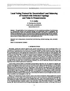
Fig. 8: a) Schematic of the test setup hardware and the block diagram of the particular GDUs, the current measurements and the communication channels. b) Top front view of the test setup hardware (without pulse inductor). Top: five interconnected GDUs, middle: isolated busbar, bottom front: 5 parallel connected IGBT modules with PCB-Rogowski coils, bottom back: DC link capacitors.
However, to compensate this delay time, an identical transformer could also be inserted between the own edge detection comparator and the control unit of a GDU.
4.2
Current amplitude signal
To transmit a sampled current amplitude value, e.g. with an 8-bit resolution, a digital communication channel between GDUs must be implemented. An asynchronous serial bus is the easiest way to implement such a communication as therewith only one connection is needed. In contrast to the current edge communication, the transmission of the current amplitude is not as time-critical, since the digital signal has to be transmitted only within one switching period (typ. around 100 µs for 10 kHz switching frequency) resulting in a rather low minimum data rate. The galvanic isolation requirements of 100 V allow to use magnetocouplers, optical links or even optocouplers. This kind of communication can therefore be implemented easily due to the low requirements concerning propagation delay and isolation voltage.
5 5.1
Experimental results Hardware setup
An isolated GDU was developed, as shown in Fig. 7, that contains the DAGC functionality: a digital control unit (FPGA), current measurement circuits with edge detection by either a Rogowski coil or the IGBT’s emitter voltage difference and communication interfaces to transmit current edges and sampled current amplitudes between GDUs both in a daisy chain control structure. To verify the proposed DAGC, a test setup consisting of a film capacitor DC link CP (up to 1 kV, 1.6 mF), 5 parallel connected Infineon FF450R12KE4 IGBT half-bridge modules (1.2 kV, 450 A) driven by the developed GDUs, an air-core pulse inductor LP (53 µH) and a low inductive busbar interconnecting all components was built. Its schematic is shown in in Fig. 8 a) and the realized hardware corresponding is depicted in Fig. 8 b). With this setup, multiple pulse tests for up to 5 parallel connected IGBT modules can be performed to measure and analyze the current sharing during turn-on and turn-off switching transients. To measure the currents of all the IGBTs, Rogowski coils, as illustrated in Fig. 5 b), are implemented in the hardware setup.
EPE 2011 - Birmingham
ISBN: 9789075815153
P.8
Decentralized Active Gate Control for Current Balancing of Parallel Connected IGBT Modules
LOBSIGER Yanick
IGBT current iC [A]
a) without DAGC 600 400 200 0
IGBT current iC [A]
b) with DAGC
1
1.5
600 400 200
2
0 0
1
2
3
4
5 6 time [µs]
7
8
9
10
8
8.5
9
Fig. 9: Measured IGBT currents a) without and b) with current amplitude DAGC (fs = 100 MHz) based on the actively integrated emitter voltage difference vEe . The current waveforms have been generated by means of measuring the implemented PCB-Rogowski coil’s voltages (cf. Fig. 5) and integrating them digitally on a PC. The gate signal delays of all 4 IGBTs have been adjusted to tdelay(1,2,3,4) = 100, 0, 20, 50 ns in both cases.
5.2
Measurements
The current distribution of 4 parallel connected IGBT modules was measured for hard turn-on and turnoff switching transients in a multi pulse test to demonstrate the performance of the DAGC. The gate signal delays of all 4 IGBTs have been adjusted to constantly tdelay(1,2,3,4) = 100, 0, 20, 50 ns. A sequence of 20 pulses was performed after which the current sharing has been measured. Without DAGC, the constant gate signal delays are not compensated, thus an unbalanced current distribution, as shown in Fig. 9 a), results. With DAGC (fs = 100 MHz) and amplitude control based on the actively integrated emitter voltage difference vEe implemented on all GDUs, the delays of the gate signals are compensated by the control units. As a consequence, the current distribution is transiently and statically almost completely balanced for all 4 IGBT modules as depicted in Fig. 9 b). If the DAGC is implemented with the edge instead of the amplitude control, also based on the emitter voltage difference vEe , a similar current distribution is achieved. It has to be mentioned, that due to the individual clocks of the control units and the sampling jitter of the PWM gate signal inputs, the DAGC is an ongoing control action where the delay times for all IGBTs may vary individually around the optimal average delays, what results in temporary slightly less balanced currents. This consequence could be minimized by increasing the FPGA’s clock frequency fs .
6
Conclusion
In this paper, the decentralized active gate control, a modular concept to balance the currents of parallel connected IGBT modules, is presented. The distributed control units on the GDUs adjust the switching times to achieve a dynamic current balancing by means of the implemented measurement and communication capability. Thanks to the modular concept, adding or removing IGBTs to and from the parallel connection without giving up the DAGC is very simple as no changes in the GDU’s hardware and software have to be executed. For the required current measurement functionalities two simple, cheap and accurate implementations are shown, whereupon in one solution the IGBT itself is used as current sensor and no additional sensing element is needed. Realization possibilities for the two different types of communication (edge or amplitude) have been investigated. To experimentally verify the performance of the proposed control, GDUs with implemented DAGC, current measurement and communication channels have been developed. It has been shown that the DAGC is able to compensate the initially existent delay times for the parallel connected IGBTs enabling a balanced current distribution. In addition to the DAGC, the digital control unit on the GDU can be applied for advanced driving methods of the IGBT. Adjusting diC /dt or dvCE /dt by a controllable output stage and improved protection functions can be handled simultaneously by the digital control unit.
EPE 2011 - Birmingham
ISBN: 9789075815153
P.9
Decentralized Active Gate Control for Current Balancing of Parallel Connected IGBT Modules
LOBSIGER Yanick
References [1] B. Abdi, A. H. Ranjbar, K. Malekian, J. Milimonfared and G. B. Gharehpetian, “Problems associated with parallel performance of high current semiconductor switches and their remedy,” Proc. of the Int. Symp. on Power Electronics, Electrical Drives, Automation and Motion (SPEEDAM), pp. 1379– 1383, 2008. [2] J. J. Nelson, G. Venkataramanan and B. C. Beihoff, “Investigation of parallel operation of IGBTs,” Proc. of the 37th IEEE Industry Applications Society Annual Meeting (IAS), vol. 4, pp. 2585–2591, 2002. [3] M. Paakkinen and D. Cottet, “Simulation of the non-idealities in current sharing in parallel IGBT subsystem,” Proc. of the 23rd Annual IEEE Applied Power Electronics Conf. and Exposition (APEC), pp. 211–215, 2008. [4] R. Alvarez, K. Fink and S. Bernet, “Simulation and experimental investigation of parallel connected IGBTs,” Proc. of the IEEE Int. Conf. on Industrial Technology (ICIT), pp. 824–831, 2010. [5] H. Miyazaki, H. Fukumoto, S. Sugiyama, M. Tachikawa and N. Azusawa, “Neutral-point-clamped inverter with parallel driving of IGBTs for industrial applications,” IEEE Transactions on Industry Applications, vol. 36, no. 1, pp. 146–151, 2000. [6] U. Scheuermann, “Paralleling of chips - from the classical ’worst case’ consideration to a statistical approach,” Proc. of the Power Conversion Intelligent Motion Conf. (PCIM Europe), 2005. [7] L. M. Selgi, G. Sorrentino, L. Fragapane and M. Melito, “Preliminary experimental evaluation on PT-IGBT in parallel connection,” Proc. of the 12th European Conf. on Power Electronics and Applications (EPE), 2007. [8] U. Schlapbach, “Dynamic paralleling problems in IGBT module contstruction and application,” Proc. of the 6th Int. Conf. on Integrated Power Electronic Systems (CIPS), 2010. [9] Fuji IGBT module application manual, www.fujisemiconductor.com, 2004. [10] W. Huiqing, L. Jun, Z. Xuhui and W. Xuhui, “Design of high power electronic building block based on parallel of IGBTs for electric vehicle,” Proc. of the 13th Power Electronics and Motion Control Conf. (EPE-PEMC), pp. 1518–1522, 2008. [11] J. Thalheim, O. Garcia and S. Pawel, “Fast gate drivers simplify parallel operation of IGBTs,” Proc. of the Power Conversion Intelligent Motion Conf. (PCIM Europe), pp. 540–545, 2009. [12] K. Sasagawa, Y. Abe and K. Matsuse, “Voltage-balancing method for IGBTs connected in series,” IEEE Transactions on Industry Applications, vol. 40, no. 4, pp. 1025–1030, Jul. 2004. [13] P. Hofer, N. Karrer and C. Gerster, “Paralleling intelligent IGBT power modules with active gatecontrolled current balancing,” Proc. of the Annual IEEE Power Electronics Specialists Conf. (PESC), vol. 2, pp. 1312–1316, 1996. [14] P. Hofer-Noser and N. Karrer, “Monitoring of paralleled IGBT/diode modules,” IEEE Transactions on Power Electronics, vol. 14, no. 3, pp. 438–444, May 1999. [15] D. Bortis, J. Biela and J. W. Kolar, “Active gate control for current balancing of parallel-connected IGBT modules in solid-state modulators,” IEEE Transactions on Plasma Science, vol. 36, no. 5, pp. 2632–2637, Oct. 2008. [16] Y. Lobsiger, D. Bortis, J. W. Kolar and M. Laitinen, “Gate driver unit for electrical switching device,” EU Patent EP10 188 454.2, Oct. 22, 2010. [17] S. Pawel and J. Thalheim, “1700v planar transformers for high power gate drives,” Proc. of the Power Conversion Intelligent Motion Conf. (PCIM Europe), pp. 753–758, 2009. [18] L. Chen and F. Z. Peng, “Closed-loop gate drive for high power IGBTs,” Proc. of the 24th Annual IEEE Applied Power Electronics Conf. and Exposition (APEC), pp. 1331–1337, 2009. [19] P. J. Grbovic, “An IGBT gate driver for feed-forward control of turn-on losses and reverse recovery current,” IEEE Transactions on Power Electronics, vol. 23, no. 2, pp. 643–652, Mar. 2008. [20] C. R. Hewson, W. F. Ray and J. Metcalfe, “Optimising high frequency integrator operation of rogowski current transducers,” Proc. of the 12th European Conf. on Power Electronics and Applications (EPE), 2007. [21] R. E. Locher, “Short circuit proof IGBTs simplify overcurrent protection,” Proc. of the 26th IEEE Industry Applications Society Annual Meeting (IAS), pp. 1497–1500, 1991. [22] R. Hemmer, “Intelligent IGBT drivers with exceptional driving and protection features,” Proc. of the 13th European Conf. on Power Electronics and Applications (EPE), 2009.