Decision Support System for Hot Spot Detection Esther SALAMÍa,1, Sol PEDRE b, Patricia BORENZSTEJNb, Cristina BARRADOa, Andres STOLIAR b and Enric PASTORb a Technical University of Catalonia b Buenos Aires University Abstract. Forest fires are an important problem for many countries. Prevention, surveillance and extinguishing tasks are costly and sometimes risky. This paper focuses on the surveillance of the fire embers once the fire is extinguished. This is a post-fire task which requires an important amount of terrestrial resources, especially if the weather conditions may provoke the re-ignition of the fire. We propose the use of an Unmanned Aerial System to support fire fighters’ decisions. Our proposal is to develop an intelligent system which can make or suggest tactical decisions to firemen on hot-spot surveillance. The Unmanned Aerial System consists of a small unmanned aircraft, a ground control station and several personal devices for the firemen on ground. All system elements are wirelessly connected. On board data acquisition and fast processing, together with an intelligent transmission and interpretation are the targets of the system. Keywords. Unmanned Aerial System, Real-Time, Image Processing, Fire Fighting
Introduction Forest fires are an important problem for many countries. The economic lost is the most visible impact in the short term. The ecological damage and the impact on the wild life diversity and on climate change are the most important lost in the long term [1]. In some dramatic cases, we should add the lost of human lives. Prevention tasks are the first way to fight against forest fire. Although all important prevention efforts done at many levels, forest fire cannot be completely avoided in some extreme climatic circumstances. Fire extinguish tasks are the second resource for fire fighting. Previous experiences on the use of UAV in fire fighting mission have been done, especially in the monitoring of currently burning fires [2][3][4]. This paper does not target to use UAS in these tasks (detection or watering) because the current aerial means in charge of them do not want interferences of another aerial mean with autonomous behavior. A third forest fire fighting task is also needed for fire embers surveillance once the fire is extinguished. At this time, an important amount of terrestrial resources is still devoted to post-fire tasks. Ground crew has to stay watering the smoking spots and many times this is done blindly. In this scenario, we propose the use of UAS to introduce intelligence to the fire fighting tasks. 1
Corresponding Author: Esther Salamí, Computer Architecture Department, UPC; EPSC, C/Esteve Terradas 7, C4-004, 08860 Castelldefels (Barcelona), Spain; E-mail:
[email protected]
The rest of this document is organized as follows: The proposed system is presented in Section 1. Section 2 describes the framing models. Details of the real time image processing are given in Section 3. Section 4 shows the data fusion algorithm. Finally, main conclusions are summarized in the last Section of the document.
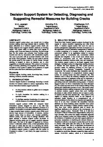
1. The UAS Based Intelligent System The Unmanned Aerial System (UAS) is an intelligent system composed of the following parts (see Figure 1): The Unmanned Aerial Vehicle (UAV), the Ground Control Station (GCS), the Communication Channels (CC) and the Squad Information Terminals (SIT). UAV is the airframe and all the devices on-board it that compose the payload; GCS is a mobile device (i.e. laptop) which is used to control the UAS flight and mission; CC are the radio connections and their related electronics and antennas; SIT are very light devices used to inform the ground crew of the current fire state.
Figure 1. System components
The UAV should flight at low altitude (from 300 to 500 m) in a range of 2 hours. The command&control requires a real time CC to have direct control of the UAV flight from the ground in case of emergency. But this is not the case for the communications related to mission. As in previous work [5], images are processed on board for an intelligent interpretation. In this paper, we propose to improve the firemen decision making with the immediate communication of hot spots to the ground teams. 1.1.UAV Architecture The payload on board the UAS is composed by two video cameras, a High Resolution (HR) camera and an Infra Red (IR) thermal one. Note that hyper-spectral cameras or scanners are not needed because the altitude is low enough to obtain good images with
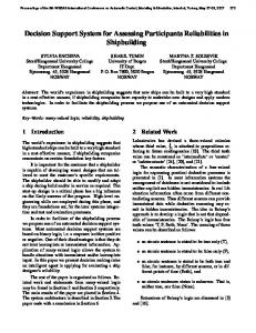
COTS cameras [6]. We do not consider including a gimbaled payload because it would make the system too much expensive. The aircraft has inertial and positioning sensors incorporated inside the Auto Pilot (AP). Additionally, the AP has a Radio Frequency (RF) modem which creates a CC between the UAV and the GCS. The range of the radio link is 100 Km. Finally, a Wi-Fi Ethernet connector is used as CC between the UAV and the near by SIT of the ground teams. The Wi-Fi channel is also used as a backup CC for connecting the UAV and the GCS. Figure 1 shows the sensors of the UAV and their connections to the on board avionics. Our architecture is network centric with one or more Line Replaceable Units (LRU) to execute other avionic functions. For this specific problem, the proposal incorporates a Field Programmable Gate Array (FPGA) to execute the IR image processing in real time. 1.2. Flight Plan Definition The flight of the UAV may need the repetition of flight patterns. It also may need modifications in case the burned area or the environmental conditions change. Thus a flexible and intelligent flight plan is needed to accomplish with the mission requirements. We define flight plan formalism as a set of stages directly related to the mission evolution. Figure 2 shows the Flight Plan stages: take-off, departure, en route, mission, arrival, approach and landing. The most relevant stage in this document is the mission stage, where the surveillance of the area to look for hot spots is done.
Figure 2. Flight Plan for fire surveillance
A Flight Plan consists of a list of RNAV based legs. We require two types of scans in a hot spot mission: an area scan and a point scan. An area scan leg is a flight pattern used to cover a whole area. This is used to locate hot spots if no previous information is given. The point scan leg is a repetitive eight turn over a fix point if the aircraft is fixed wing or a hold if the aircraft is a helicopter. It is used for a more detailed study of a possible hot spot in order to confirm or discard it. We also define parametric legs. They have dynamic behavior and allow adapting the flight to the mission evolution. 1.3 Hot Spot Mission The mission is implemented as a set of software services that orchestrate the whole operation of the UAS. This operation is greatly dependent on the flight plan evolution and payload activation and deactivation is linked to the given UAV position. The
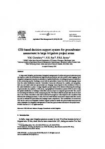
Mission Operator may introduce at any time of the mission the updates of the parametric values of a scan and the UAS will adapt the flight to the new coordinates automatically. Furthermore, the avionic services on board might also decide new parameters for the scan legs, for example if a hot spot is found. The hot spot mission defines an initial scan area leg (like in Figure 2) with a flight altitude of 500 m. Thermal images are processed in real time to detect the hot areas. When the image processing algorithm of the FPGA detects a possible hot spot, the Mission Operator and the closest ground crew SIT will receive a notification with the fused image. The visual images, which contain the surroundings of the fire and can help experts to discard false positives, are annotated with the detected hot spots. In case of doubt the Mission Operator can start a scan point leg, with an altitude of 300 m, for a more precise image. Figure 3 shows the process and the results for a given input. IR frame
DETECTION
Hot Spot data
Visual frame
Fused image
FUSION
Figure 3. Software architecture for image fusion
2. Framing Systems Model Because of price and performance trade-offs, we chose the FLIR A320 camera, a radiometric thermal camera working in the wavelength range from 7.5 to 13.0 µm and in the thermal range from 0 to 350ºC. It provides 320 x 240 pixel images of 32 bit floating point absolute temperature values. The visual camera is the Lumenera Le11059c 11 Megapixel network camera with Tamron A09 zoom lens. The relevant characteristics of these cameras are summarized in Table 1. Table 1. Specifications of the cameras
ThermoVision A320 Spectral range: Temperature. range: Field of view: Focal length: F-number: Resolution: Frame rate:
7.5 to 13 µm 0 to 350ºC (±2ºC) 25.0º x 18.8º 18 mm 1.3 320 x 240 pixel 9 fps
Lumenera Le11059c + Tamron A09 Field of view: 75º-32º (diagonal) Focal length: 28-75 mm F-number: 1-2.8 Resolution: 4000 x 2656 pixel Frame rate: 3 fps
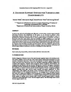
In our system, the thermal and the visual cameras are tied together in an upright position, as shown in Figure 4.. We consider a simple projection model with the coordinate system centered in the focus lens. The focus distance (in our case the flight altitude) titude) is large enough to assume that both cameras are are positioned at the same point, thus the center of the thermal and visual pictures coincide; but as each camera has its own Field Of View iew (FOV), (FOV the captured areas are different in size. For the A320, when w flying at an AGL of 300 m one thermal picture covers an area of 133 x 100 m2, which represents a precision of 0.4 0. m per pixel. As the thermal camera has lower resolution, one pixel in the thermal image will match several pixels in the visual one. Y
αv αt
αty: Y-axis FOV of the thermal camera αvy: Y-axis FOV of the visual camera Ht: height captured by the thermal camera Hv: height captured by the visual camera
Z H H Figure 4. Cameras model (Y axis view)
3. Real Time Algorithm The real time part of the algorithm processes video from the IR Camera and detects hot spots. The architecture (Figure 5) consists of ann analog to digital converter for the cameras analogical output, an FPGA that performs the hot spot detection, and an Ethernet driver that transmits the resulting output in an UDP UDP frame with the detected hot spot data: (a) the time stamp when the image was captured, (b) the rectangle containing the hot spot, and (c) the coordinates of the hot spot center of mass.
Figure 5. IR board architecture
The FPGA algorithm consists of five code modules and three input/output configuration modules. The first code module generates the RAW stream by extracting the temperature pixels from the digitalized video. The following module classifies each pixel as a hot spot depending on its IR radiation. A third module, the segmentation module, is the core of the detection algorithm. It groups the pixels belonging to the same hot spot. In image processing, segmentation is the process that divides an image in homogeneous regions. Its complexity lies in grouping the pixels in hot spots as the image is being captured. The developed algorithm (Listing 1) performs the segmentation of the image using only the current pixel and the previous line of pixels. Listing 1. Segmentation algorithm input: pixel(m,n) and previous line of pixels L receive pixel(m,n) if (pixel(m,n) does not belong to a hot spot) mark in the line L that pixel(m,n) does not belong to a hot spot. if (pixel(m,n) belongs to a hot spot) if (pixel(m-1,n) and pixel(m,n-1) do not belong to hot spots) create a new hot spot for pixel(m,n) mark pixel(m,n) in the line L as belonging to the new hot spot if (pixel(m-1,n) belongs to hot_spot_x and pixel(m,n-1) does not belong to any hot spot) or (pixel(m-1,n) does not belong to any hot spot and pixel(m,n-1) belongs to hot_spot_x) or (pixel(m-1,n) and pixel(m,n-1) belong to hot_spot_x)) add pixel(m,n) to hot_spot_x in the memory mark pixel(m,n) in line L as belonging to hot_spot_x if (pixel(m-1,n) belongs to hot_spot_x and pixel(m,n-1) belongs to hot_spot_y) add hot_spot_y data to hot_spot_x in the memory add pixel(m,n) to hot_spot_x in the memory mark pixel(m,n) in line L as belonging to hot_spot_x for each pixel in line L if (pixel belongs to hot_spot_y) mark pixel as belonging to hot_spot_x
The 4th module is a shared memory double buffer. It is organized as a vector of records, with one record for each hot spot. Each record stores the coordinates of the rectangle containing the hot spot and the necessary data to calculate the hot spots center of mass. The segmentation module recalculates this data every time a new pixel is added to a hot spot or when two hot spots, say hot_spot_x and hot_spot_y, are unified. When pixel(m, n) is added to line L, pixel(m, n-1) is discarded. In this way, the line always contains the same number of pixels. The last code module implemented in the FPGA generates UDP packages with the data in the shared memory. The memory module has been designed to have a double buffer such that the UDP module can execute in parallel with the segmentation. The partial results of the current image are stored in one buffer, while the final results of the previous image are stored in the other one. Finally, the data configuration modules are for the input digitalizing parameters, for the output Ethernet driver (IP address and port number) and for the threshold values of the classifier module.
4. Data Fusion Algorithm Visual processing is the most time consuming part of the algorithm due to the high resolution of the image and to the JPEG coding and decoding process. Nevertheless,
the proposed fusion of the two pictures takes less than 1.2 seconds to execute in a conventional computer, including the image file access. This time is acceptable for this part of the application, as thermal and visual fusion will be provided only for critical frames on which a hot spot is detected. The fusion of the thermal and visual images is the result of two steps: First, mapping of the thermal and visual pixel coordinates, and second, acting on the visual pixel value. Being pt[mt,nt] a pixel on the thermal image, there is a matrix of pixels pvkl[mvk, nvl] that correspond to the same physical area in the visual image: p [m , n ] L v11 v1 v1 pt [mt , nt ] ↔ M O p m n [ , ] vK 1 vK v1 L
pv1L [mv1 , nvL ] M pvKL [mvK , nvL ]
(1)
The relation between those thermal and visual pixel coordinates can be computed as the composition of scaling and translation functions: mv1 = mt − Ttm ⋅ S m + Tvm nv1 = nt − Ttn ⋅ S n + Tvn
( ) ( ) mv = (mt + 1 − Ttm )⋅ S m + Tvm − 1 nv = (nt + 1 − Ttn )⋅ S n + Tvn − 1
(2)
K
L
The translation and scale factors depend only on the angle of view and the resolution of the cameras, and can be inferred from Figure 4 applying simple geometry: Ttm =
Sm =
Mt M ; Tvm = v ; 2 2 Mv Mt
⋅
tan(α ty / 2) tan(α vy / 2)
;
Ttn =
N Nt ; Tvn = v 2 2
N tan(α tx / 2) Sn = v ⋅ N t tan(α vx / 2)
(3)
Where M: image width in pixels W: captured width in meters αx: X-axis angle of view
N: image height in pixels H: captured height in meters αy: Y-axis angle of view
Subscript t is used for the thermal camera parameters and subscript v for the visual ones. Usually both cameras have square pixels, and Sm and Sn are the same value. The thermal coordinates of the rectangle and the center of mass provided by the FPGA are translated into visual coordinates using Eqs. (2). The rectangle coordinates are used to draw a black rectangle, by just zeroing the three color channels of the related visual pixels. The visual pixels corresponding to the center of mass, together with their neighbors in a radius of 8 visual pixels, are emphasized in red as follows: The red channel is enhanced (pv(r) = 127+0.5 · pv(r)), the green component is removed (pv(g) = 0), and the blue channel is softened (pv(b) = 0.5 · pv(b)). An example of a resulting image is given in Figure 3.
5. Conclusions In this document we present an aerial intelligent system designed to aid in the Catalonia local fires fighting. The mission objective is to provide the locations of the hot spots of a post-fire, using one UAS equipped with IR and visual cameras. The selection of this mission was done because: a) the closed air space limits the safety considerations, b) the current alternative solution has a high cost, c) the user learning process is fast, and d) the complexity of the solution can progressively be incremented. The intelligent UAS is composed by a UAV, a GCS and several personal SIT. The UAS will evaluate an area and automatically inform to the closest ground firemen about the hot spots. The system is oriented to tactical response and it is supervised at any time by the operator in command. This is a new approach for the hot spot mission that takes advantage of an on board FPGA which executes a real time hot spot detection algorithm. Since not all geographical scenarios are equivalent, countries with large unpopulated areas may require more emphasis on fire detection. On large countries like Australia, it may be interesting to work on fire perimeter detection. Crop monitoring, search and rescue, or any other missions may require more attention to ATM integration. Large endurance airframes are also of interest for future civil missions, once we can provide a successful story.
Acknowledgments This work has been partially funded by AGAUR under contract 2007ITT-0014 and by Ministry of Education of Spain under contract TIN2007-63927.
References [1] X. Ubeda et al, Effects of prescribed fire on soil quality in Mediterranean grassland (Prades Mountains, north-east Spain), International Journal of Wildland Fire, International Association of Wildland Fire, 2005. [2] Ágoston Réstas. “Research and development of the aerial reconnaissance and extinguishing of forest fires”. PhD dissertation at the National Defence University, Budapest, Hungary, Oct 2008. [3] WRAP team, WRAP project, http.//geo.arc.nasa.gov/sge/WRAP/ [4] T.H. Cox, I. Somers, D.J. Fratello, Earth Observation and the Role of UAVs: A Capability Assessment. Version 1.1, NASA Report www.nasa.gov/centers/dryden/research/civuav, 2006. [5] Enric Pastor, Cristina Barrado, Pablo Royo, Juan Lopez, Eduard Santamaria, Xavier Prats, and Josep M Batlle, Red-Eye: A Helicopter-Based Architecture for Tactical Wildfire Monitoring Strategies. AIAA Aerospace Conference, Big Sky, MT, 2009. [6] S.E. Dunagan et al, A Multi-Sensor Imaging Payload for Mission-Adaptive Remote Sensing Applications, AIAA Infotech@Aerospace, Arlington, VI, 2005.