We present a formal technique for safe distribution of workflow pro- ... guage such as Business Process Model and Notation (BPMN) [36] in which the control ...... International Symposium on Fundamentals of Software Engineering (FSEN), ...
Declarative Modelling and Safe Distribution of Healthcare Workflows Thomas Hildebrandt1 , Raghava Rao Mukkamala1 , and Tijs Slaats1,2 ? 1 IT University of Copenhagen Rued Langgaardsvej 7, 2300 Copenhagen, Denmark {hilde, rao, tslaats}@itu.dk, http://www.itu.dk 2 Exformatics A/S, 2100 Copenhagen, Denmark
Abstract. We present a formal technique for safe distribution of workflow processes described declaratively as Nested Condition Response (NCR) Graphs and apply the technique to a distributed healthcare workflow. Concretely, we provide a method to synthesize from an NCR Graph and any distribution of its events a set of local process graphs communicating by shared events, such that the distributed execution of the local processes is equivalent to executing the original process. The technique is based on our recent similar work on safe distribution of Dynamic Condition Response (DCR) Graphs applied to cross-organizational case management. The contributions of this paper is to adapt the technique to allow for nested processes and milestones and to apply it to a healthcare workflow identified in a previous field study at danish hospitals.
1
Introduction
The overall goal of the interdisciplinary Trustworthy Pervasive Healthcare Services (TrustCare) project [17] is to develop a foundation for trustworthy it-supported healthcare workflows. Healthcare workflows involve coordination of a heterogeneous set of professionals, patients, organizations and sectors, and must be able to adapt to inevitable changes of treatment processes and organization of the work [23, 41]. This challenges traditional workflow management systems using an imperative process modeling language such as Business Process Model and Notation (BPMN) [36] in which the control flow is modeled explicitly. Typically a flow diagram will only cover the normal flow and a few possible exceptionally flows, leading to rigid and inflexible, over-specified workflows. Declarative process languages, allowing any flow that fulfill the specified constraints, have been suggested by a number of researchers as being more appropriate for representing workflow processes requiring a high degree of flexibility [9–11,34,44]. The TrustCare project combines research in pervasive user-interfaces [2, 3] with research in formal logic and domain specific process languages, taking as starting point [32] the declarative workflow process language developed and used by Resultmaker, the industrial partner of the project. ?
Authors listed alphabetically. This research is supported by the Danish Research Agency through the Trustworthy Pervasive Healthcare Services project (grant #2106-07-0019, www.trustcare.eu) and the Computer Supported Mobile Adaptive Business Processes project (grant #274-06-0415, www.cosmobiz.dk).
2
Hildebrandt, Mukkamala, Slaats
The present paper focus on and extends our work on formal process languages, in particular the development of a basic formal declarative workflow language called Dynamic Condition Response Graphs (DCR Graphs) introduced in [18] and extended to allow nested (i.e. hierarchical) process definitions in [19, 20]. Most recently [21] we have shown how, given a (non-nested) DCR Graph describing a global, collaborative process and any distribution of the activities, to derive a set of local DCR Graphs corresponding to the activity distribution and achieving the same global behavior by synchronously communicating the relevant events between the local processes. The main new contribution of the present paper is to adapt the distribution technique to nested processes as introduced in [20] and demonstrate its use on a small oncology healthcare workflow previously identified during a field study at danish hospitals [26] and described loc. cit. using an early formalization of the Resultmaker workflow process language. We also provide a new formalization of the oncology example and a new presentation of the formal semantics of the model that highlights the declarative nature. To make the exposition more accessible we restrict the formal model to the primitives needed for the example and leave out the primitives of DCR Graphs for dynamically changing the set of included activities in the workflow, leading to the simpler model of Nested Condition Response (NCR) Graphs. However, by combining the results of the present paper with the ones in [21] they generalize to the full model of Nested DCR Graphs. The intention of the oncology healthcare workflow is to illustrate two important kinds of flexibility appearing in healthcare workflows: 1) The need for reconsidering a previous activity if its validity at a later stage is questioned by a co-worker and 2) The need for distribution of collaborative tasks and ability to tailor this distribution to local conditions (e.g. the size and organization of work within a hospital). As pointed out by a reviewer of our work, these needs are not specific to the healthcare domain. Indeed, the same needs have been identified during field studies of case management processes [19]. We regard it as an advantage of the example that it is generally relevant for knowledge work processes and not only healthcare workflows. The use of a workflow extracted from a field study carried out at a hospital allowed us to present our work more easily to nurses and physicians and has confirmed that the issues of flexibility are real concerns. It is important to stress, as also pointed out by reviewers of the paper, that the example workflow does not show how the techniques deal with a complex and complete healthcare workflow. This would require a much larger field study and extensions to the model in order to deal with e.g. time, data and constraint violations (i.e. soft constraints [4]). When the TrustCare project is finished early 2012 we hope to have developed these extensions to the DCR Graph language as well as having developed a prototype integration of the language with the pervasive user interface technology developed in the other track of the project [2, 3]. This, as well as further feedback on our work when presented at FHIES 2011 [22] would provide the basis for a larger field study and demonstration project applying the techniques to a much more complete healthcare workflow. The rest of the paper is structured as follows. In Sec. 1.1 ending the introduction we briefly discuss related work. We present the oncology workflow example in Sec. 2 as a Nested Condition Response (NCR) Graph, describing the semantics informally. In
Declarative Modelling and Safe Distribution of Healthcare Workflows
3
Sec. 3 we give the formal definition of NCR Graphs and their semantics. We then in Sec. 4 formalize the distribution technique and in Sec. ?? exemplify it on the oncology workflow. Finally we conclude in Sec. 5. 1.1
Related Work
There are many researchers [1, 25, 27, 40, 42, 43, 47] who have explicitly focussed on the problem of verifying the correctness of cross-organizational workflows described as variants of Petri nets. Also, many researchers have studied how to model global behavior as a set of conversations among participating services [5, 6, 15, 37, 49, 50]. A technique to partition a composite web service using program analysis was studied in [35] and using a similar approach, [24] explored decomposition of a business process modeled in BPEL, primarily focussing on P2P interactions . Using a formal approach based on I/O automata representing the services, the authors in [29] have studied the problem of synthesizing a decentralized choreography strategy, that will have optimal overhead of service composition in terms of costs associated with each interaction. The derivation of descriptions of local components from a global model has also been researched for the imperative choreography language WS-CDL in the work on structured communication-centred programming for web services by Carbone, Honda and Yoshida [7]. To put it briefly, the work formalizes the core of WS-CDL as the global process calculus and defines a formal theory of end-point projections projecting the global process calculus to abstract descriptions of the behavior of each of the local ”end-points” given as pi-calculus processes typed with session types. A methodology for deriving process descriptions from a business contract formalized in a formal contract language was studied in [28], while [39] proposes an approach to extract a distributed process model from collaborative business process. In [13, 14], the authors have proposed a technique for the flexible decentralization of a process specification with necessary synchronization between the processing entities using dependency tables. In [8, 16, 33] foundational work has been made on synthesizing distributed transition systems from global specification for the models of synchronous product and asynchronous automata [51]. In [33] Mukund categorized structural and behavioral characterizations of the synthesis problem for synchronous and loosely cooperating communication systems based on three different notions of equivalence: state space, language and bisimulation equivalence. Further Castellani et. al. [8] characterized when an an arbitrary transition system is isomorphic to its product transition systems with a specified distribution of actions and they have shown that for finite state specifications, a finite state distributed implementation can be synthesized. Complexity results for distributed synthesis problems for the three notions of equivalences were studied in [16]. The formalisms discussed above are all confined to imperative modeling languages such as Petri nets, workflow/open nets and automata based languages. To the best of our knowledge, there exists very few works on distributed cross-organizational workflows which consider declarative modeling languages and none where both the global and local processes are given declaratively using the same formalism. The latter allows us to further split a local model if needed. In [12], Fahland has studied synthesizing declarative workflows expressed in DecSerFlow [46] by translating to Petri nets. Only
4
Hildebrandt, Mukkamala, Slaats
a predefined set of DecSerFlow constraints are used in the mapping to the Petri nets patterns, so this approach has a limitation with regards to the extensibility of the DecSerFlow language. On the other hand, in [30] Montali has studied the composition of ConDec [45] models with respect to conformance with a given choreography, based on the compatibility of the local ConDec models. But his study was limited to only composition of local models, whereas the problem of splitting a global model in local models has not been studied.
2
Distributed Declarative Healthcare Workflows by Example
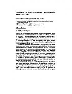
In Fig. 1 below we show the graphical representation of the Nested Condition Response Graph formalizing the oncology workflow studied in [26]. In this section we informally describe the formalism and the distribution technique formalized in the rest of the paper using the example workflow. For details of the field study and the workflow we refer the reader to [26].
Fig. 1. Oncology Workflow as an NCR Graph
The boxes denote activities (also referred to as events in the following sections) and the arrows denote relations between activities constraining their execution. Administer medicine is a nested activity having sub activities give medicine and trust. Give
Declarative Modelling and Safe Distribution of Healthcare Workflows
5
medicine is an atomic activity, i.e. it has no sub activities. Trust is again a nested activity having sub activities sign nurse 1 and sign nurse 2. Finaly, medicine preparation is a nested activity having seven sub activities dealing with the preparation of medicine. A run of the workflow consists of a (possibly infinite) sequence of executions of atomic activities. (A nested activity is considered executed when all its sub activities are executed). An activity can be executed any number of times during a run, as long as the constraints for executing it are satisfied, in which case we say the activity is enabled. The constraints are expressed as relations between activities represented as arrows in the figure above. The example uses three core relations: The condition relation, the response relation and the milestone relation. The condition relation is represented by an arrow from an activity A to another activity B with a bullet at the arrow head. It denotes that the previous execution of activity A is a condition for executing activity B. E.g. the activity patient data (consulting the medical record) must have been executed at least once before the activity prescribe medicine can be executed. The response relation is represented by an arrow from an activity A to another activity B with a bullet at its source. It denotes that activity B must be executed (at some point) after any execution of activity B (as a response). E.g. the activity give medicine must be executed (at some point) after (any execution of) the activity prescribe medicine. We say that a workflow is in a completed state if all such response constraints have been fulfilled. However, note that a workflow may be continued from a completed state and change to a non-completed state if an activity is executed that requires a response. Also note that the response constraint may cause some infinite runs to never pass through a complete state if the executed activities keep triggering new responses. In the following section we make precise when such infinite runs can be regarded as a complete execution. The third and final core relation used in the example is the milestone relation, an arrow from an activity A to another activity B with a diamond at the arrow head. It denotes that the activity B can not be executed if activity A has not been executed since it has been required as a response. I.e. activity A is a milestone that must be reached (i.e. be completed) for the activity B to be executed. The milestone relation was introduced in [20] jointly with the ability to nest activities. A relation to and/or from a nested activity simply unfolds to relations between all sub activities. A milestone relation from a nested activity to another activity A then in particular means that the entire nested activity must be in a completed state before activity A can be executed. E.g. medicine preparation is a milestone for the activity administer medicine, which means that none of the sub activities of administer medicine can be carried out if any one of the sub activities of medicine preparation has not been executed since it was required as a response. Two activities can be related by any combination of core constraints. In the graphical notation we have employed some shorthands, e.g. indicating the combination of a condition and a response relation by and arrow with a bullet in both ends. As already mentioned in the introduction, NCR Graphs as informally described above is a sub language of Nested DCR Graphs. DCR Graphs allow two more core relations for respectively dynamic exclusion and dynamic inclusion of activities. Since
6
Hildebrandt, Mukkamala, Slaats
these relations are not used in the example we decided to leave them out from the definitions in the present paper, which allows us to simplify the exposition and hopefully make it more accessible. The run-time state of an NCR Graph can be formally represented as a pair (Ex, Re) of sets of atomic activities (referred to as the marking of the graph). The set Ex is the set of atomic activities that have been executed at least once during the run. The set Re is the set of atomic activities that are required to be executed at least one more time in the future as the result of a response constraint (i.e. they are pending responses). The set Ex thus may be regarded as a set of completed activities and the set Re as the set of activities on the to-do list. However, note that an activity may be completed once and still be on the to-do list, which simply means that it must be executed (completed) again. This makes it very simple to model the situation where an activity needs to be (re)considered as a response to the execution of an activity. In the oncology example this is e.g. the case for the response relation between the don’t trust prescription(N) activity (representing that a nurse reports that he doesn’t trust the prescription) and the sign doctor activity. The effect is that the doctor is asked to reconsider her signature on the prescription. In doing that she may or may not decide to change the prescription, i.e. execute prescribe medicine again. We indicate the marking graphically by adding a check mark to every atomic activity that has been executed (i.e. is included in the set Ex of the marking) and an exclamation mark to every atomic activity which is required to be executed at least once more in the future (i.e. is included in the set Re). In Fig. 1 we have shown an example marking where protocol assignment, patient data and prescribe medicine have been executed. This has caused sign doctor and give medicine to be required as responses, i.e the two activities are included in the set Re of the marking (on the to-do list). As described above, an activity can be executed if it is enabled. Sign doctor is enabled for execution in the example marking, since its only condition (prescribe medicine) has been executed and it has no milestones. Give medicine on the other hand is not enabled since it has the (nested) activity trust as condition, which means that all sub activities of trust (sign nurse 1 and sign nurse 2) must be executed before give medicine is enabled. Also, both give medicine and trust are sub activities of administer medicine which further has sign doctor as condition and milestone, and medicine preparation as milestone. The condition relation from sign doctor means that the prescription must be signed before the medicine can be administered. The milestone relations means that the medicine can not be given as long as sign doctor or any of the sub activities of medicine preparation is on the to-do list (i.e. in the set Re of pending responses). Every activity should not be available to any user of the workflow system. For this reason the commercial implementation of the workflow management system provided by Resultmaker employs a role based access control, assigning to every atomic activity a finite set of roles and assigning to every role a set of access rights controlling if the activity is invisible or visible to users fulfilling the role. If an activity is visible it is specified wether the role are allowed to execute the activity or not. Users are either statically (e.g. by login) or dynamically assigned to roles (e.g. by email invitation).
Declarative Modelling and Safe Distribution of Healthcare Workflows
7
In the formalization presented in this paper, the assigned roles are given as part of the name of the activity. In the graphical representation we have shown the roles within small ”ears” on the boxes. In the example workflow we have the following different roles: Doctor (D), Controlling Pharmacist (CP), Pharmacist Assistant (PA) and Nurse (N). Hereto comes roles N1 and N2 which must dynamically be assigned to two different authorized persons (nurses or doctors). This is at present the only way to implement the constraint stating that two different authorized persons must sign the product prepared by the pharmacists before the medicine is administered to the patient. Future work will address less ad hoc ways to handle these kind of constraints between activities referring to the identify of users. The commercial implementation is based on a centralized workflow manager controlling the execution of the entire, global workflow. However, workflows often span different units or departments within the organization, e.g. the pharmacy and the patient areas, or even cross boundaries of different organizations (e.g. different hospitals). In some situations it may be very relevant to execute the local parts of the workflow on a local (e.g. mobile) device without permanent access to a network, e.g. during preparation of the medicine in the pharmacy. Also, different organizations may want to keep control of their own parts of the workflow and not delegate the management to a central service. This motivates the ability to split the workflow in separate components, each only referring to the activities relevant for the local unit and being manageable independently of the other components. The technique for distributing DCR Graphs introduced in [21] and extended in the present paper is a first step towards supporting this kind of splitting of workflow definitions. Given any division of activities on local units (assigning every activity to at least one unit) it describes how to derive a set of graphs, one for each unit, describing the local part of the workflow. Such a local process, referred to as a projection is again a DCR Graph. It includes the activities assigned to the unit but also the relevant external activities executed within other units for which an event must be send to the local process when they are executed. An example of a projection relative to the activities assigned the doctor role (D) is given in Fig. 2(a) in Sec. 4. The diagram shows that the projection also includes the two external activities (indicated as double line boxes) don’t trust prescription (N) and don’t trust prescription (CP). These two activities, representing respectively a nurse and a controlling pharmacist reporting that the prescription is not trusted, are the only external activities that may influence the workflow of the doctor by requiring sign doctor as a response. Similarly, Fig. 2(b),2(c), and 2(d) shows projections corresponding to the nurse, controlling pharmacist, and pharmacist assistant roles. However, if for instance the roles of the controlling pharmacist and the pharmacist assistant are always assigned to the same persons one may instead choose to keep all these activities together in a unit. This can be obtained by simply projecting on all activities assigned either the CP or the PA role.
3
Nested Condition Response Graphs
Dynamic Condition Response (DCR) Graphs [18] is both a generalization of labelled event structures [48] and the Process Matrix workflow model developed by Result-
8
Hildebrandt, Mukkamala, Slaats
maker, our industrial partner in the TrustCare research project. DCR Graphs was extended in [20] to Nested DCR Graphs, supporting sub graphs and a new milestone relation, motivated by a case study of cross-organizational case management [19]. As described above we consider in the present paper a restricted nested model in which the set of available activities is static, which we will refer to as Nested Condition Response (NCR) Graphs. We employ the following notations. Notation: For a set A we write P(A) for the power set of A. For a binary relation →⊆ A × A and a subset ξ ⊆ A of A we write → ξ and ξ → for the set {a ∈ A | (∃a0 ∈ ξ | a → a0 )} and the set {a ∈ A | (∃a0 ∈ ξ | a0 → a)} respectively. Also, we write →−1 for the inverse relation. Finally, for a natural number k we write [k] for the set {1, 2, . . . , k}. We then formally define (Nested) Condition Response Graph as follows. Definition 1. A Condition Response Graph G is a tuple (E, M, →•, •→, →�, L, l), where (i) (ii) (iii) (iv) (v) (vi) (vii)
E is the set of events (or activities) M = (Ex, Re) ∈ M(G) is the marking where M(G) =def P(E) × P(E) , →•⊆ E × E is the condition relation •→⊆ E × E is the response relation →�⊆ E × E is the milestone relation L is the set of labels l : E → P(L) is a labeling function mapping events to sets of labels.
A Nested Condition Response Graph (NCR Graph) G is a tuple (E, B, M, →•, •→, →� , L, l), where (i) (E, B, M, →•, •→, →�, L, l) is a Condition Response Graph and (ii) B : E * E is a partial function mapping an event to its super-event (if defined), and (iii) M ∈ P(atoms(E)) × P(atoms(E)), where atoms(E) = E\{e ∈ E | ∃e0 ∈ E. B (e0 ) = e} is the set of atomic events. We write e B e0 if e0 = Bk (e) for 0 < k, referred to as the nesting relation. We already introduced the graphical notation for NCR Graphs by example in the previous section. The tuple corresponding to the NCR Graph in Fig. 1 is (partly) defined as (E, B, M, →•, •→, →�, L, l) where – E = {protocol assignment, patient data, prescribe medicine, sign doctor,. . .}, – B(e) = administer medicine, if e ∈{give medicine, trust} and B(e) = trust, if e ∈{sign nurse 1, sign nurse 2} and B(e) = medicine preparation, if e ∈{accept prescription, don’t trust prescription, make preparation, ....} and undefined otherwise, – M = (∅, ∅), – →•= {(patient data, prescribe medicine), (protocol assignment, prescribe medicine), ...}, – •→= {(prescribe medicine, sign doctor), (sign doctor, accept prescription), ...}, – →�= {(protocol assignment, prescribe medicine), (sign doctor, medicine preparation), ...}, – L = {(patient data, D), (patient data, N), (sign doctor, D), ...}
Declarative Modelling and Safe Distribution of Healthcare Workflows
9
– l(patient data) = {(patient data, D), (patient data, N)}, l(sign doctor) = {(sign doctor, D)}, ... and l(medicine preparation) = ∅, l(administer medicine) = ∅, ... Note that the labels of events consist of the name of the event and a role which defines who can execute that event. In our implementation every event can be assigned any number of roles and every user of the system can have multiple roles. A user can then execute an event if she has at least one role that is assigned to the event. To define the execution semantics for Nested Condition Response Graphs we first define how to flatten a nested graph to the simpler Condition Response Graph. Essentially, all relations to and/or from nested events are extended to sub events, and then only the atomic events are preserved. We parametrize the flattening by a function lf : P(L)∗ → P(L0 ) defining the labels of atomic events as a function of the sequence of labels labeling the chain of super events starting by the event itself: e B e1 . . . ek 6 B. Since only the atomic events in the oncology example workflow have labels we can choose as flattening function on labels the function that returns the label set of the atomic event: lf (A0 .A1 . . . Ak ) = A0 . Below we will often leave out the flattening function when it is not important in the context. Definition 2. For an NCR Graph G = (E, B, M, →•, •→, →�, L, l), set of labels L0 and a flattening function for labels lf : P(L)∗ → P(L0 ) define the underlying flat Condition Response Graph as G[lf = (atoms(E), M, →•[ , •→[ , →�[ , L0 , l[ ) where rel[ = DrelE for some relation rel ∈ {→•, •→, →�} and l[ (e0 ) = lf (A0 .A1 .A2 . . . Ak ) if e0 B e1 B e2 . . . B ek 6 B and l(ei ) = Ai , for 0 ≤ i ≤ k. It is easy to see from the definition that the underlying Condition Response Graph has at most as many events as the nested graph and that the size of the relations may increase by an order of n2 where n is the number of atomic events. Below we give a new presentation of the semantics of Condition Response Graphs stressing its declarative nature. First we formalize in Def. 3 that an event e of a (flat) Condition Response Graph is enabled when all the events that are conditions for it are in the set of executed events (i.e. (→• e) ⊆ Ex) and none of the events that are milestones for it are in the set of pending response events (i.e. →� e⊆ E\Re). Definition 3. For a Condition Response Graph G = (E, M, →•, •→, →�, L, l), and M = (Ex, Re) we define that an event e ∈ E is enabled, written G ` e, if →• e⊆ Ex and →� e⊆ E\Re. Def. 4 below then defines the change of the marking when an enabled event is executed: First the event is added to the set of executed events and removed from the set of pending responses. Then all events that are a response to the event are added to the set of pending responses. Note that if an event is a response to itself, it will remain in the set of pending responses after execution.
10
Hildebrandt, Mukkamala, Slaats
Definition 4. For a Condition Response Graph G = (E, M, →•, •→, →�, L, l), where M = (Ex, Re) and an enabled event G ` e , the result of executing e is the Condition Response Graph G = (E, M0�, →•, •→, →�, L, l), where M0 = (Ex, Re) ⊕G e =def Ex ∪ {e}, (Re \ {e}) ∪ e •→ We now define the semantics for Nested Condition Response Graphs by using the corresponding flat graph. Definition 5. For a Nested Condition Response Graph G = (E, B, M, →•, •→, →� , L, l), where M = (Ex, Re) we define that e ∈ atoms(E) is enabled, written G ` e, if G[ ` e. Similarly, the result of executing G ` e is defined as: (Ex, Re) ⊕G[ e. As an example, the marking M will be ({patient data, protocol assignment}, ∅) in a run starting from the initial marking (∅, ∅) and then executing patient data and protocol assignment (in any order). According to Def. 3 we have with this marking that G ` prescribe medicine, , i.e. the event prescribe medicine is enabled, because →• prescribe medicine = {patient data, protocol assignment} and →� prescribe medicine = {protocol assignment} ⊆ E\∅. After executing prescribe medicine, according to Def. 4, the new marking M 0 = M ⊕G prescribe medicine = ({patient data, protocol assignment, prescribe medicine}, {sign doctor, give medicine}). That is, prescribe medicine is added to the set of executed events, and sign doctor and give medicine are added to the set of pending responses, because prescribe medicine •→= {sign doctor, give medicine}. From the semantics defined above we can construct a labelled transition system with acceptance conditions for finite and infinite computations. If the Condition Response Graph is finite the transition system is also finite and can be used for model checking Condition Response Graphs (e.g. via a mapping to B¨uchi-automata) as described in [19, 31]. We will also refer to this transition system when describing the projection and distribution technique in the following section. However, note that the semantics of the distributed graphs can be given declaratively similarly to the one given in the present section. Definition 6. For a Condition Response Graph G = (E, M, →•, •→, →�, L, l), we define the corresponding labelled transition system T S(G) to be the tuple (M(G), M, EL(G), →), where EL(G) = E × L is the set of labels of the transition system, M is the initial marking, and →⊆ M(G) × EL(G) × M(G) is the transition relation defined by (e,a)
M −−−→ M ⊕G e if G ` e and a ∈ lG (e). We define a run a0 , a1 , . . . of the transition system to be a sequence of labels of a (ei ,ai )
sequence of transitions Mi −−−−→ Mi+1 starting from the initial marking. We define a run to be accepting (or completed) if for the underlying sequence of transitions it holds that ∀i ≥ 0, e ∈ Rei .∃j ≥ i.(e = ej ). In words, a run is accepting/completed if every required response event happens at some later stage. Finally, we extend the transition (e,a)
relation to a relation between graphs by (E, M, →•, •→, →�, L, l) −−−→ (E, M ⊕G (e,a)
e, →•, •→, →�, L, l) if M −−−→ M ⊕G e.
Declarative Modelling and Safe Distribution of Healthcare Workflows
4
11
Projections and Distributed Execution
In this section we define in Sec. 4.1 the notion of projection of an NCR Graphs, restricting the graph to a subset of the events, and in Sec. 4.2 we define the technique for distributing an NCR Graph as a set of local NCR Graphs obtained as projections and communicating by notifications of event executions. 4.1
Projections
An NCR Graph G is projected with respect to a projection parameter δ = (δE , δL ), where δE ⊆ E is a subset of the events of G satisfying that B(δE ) ⊆ E, i.e. the subset is closed under the super event relation, and δL ⊆ L is a subset of the labels. The intuition is that the graph is restricted to only those events and relations that are relevant for the execution of events in δE and the labeling is restricted to the set δL . The technical difficulty is to infer the events and relations not in δE , referred to as external events below, that should be included in the projection because they influence the execution of the workflow restricted to the events in δE . Fig. 2 shows examples of projections of the oncology workflow with respect to different roles. For instance, Fig. 2(a) shows the projection with respect to the projection parameter (δE , δL ) where δE ={protocol assignment, patient data, prescribe medicine, sign doctor} and δL ={(protocol assignment, D), (patient data, D), (prescribe medicine, D), (sign doctor, D)}. The two events don’t trust prescription (N) and don’t trust prescription (CP) shown with double line borders are external events included in the projected graph even though they don’t appear in the projection parameter. It is interesting to note that the doctor only needs to be aware of these two activities carried out by other participants. In comparison, the projection over the roles for nurses (N and N1) contains all the events since they may influence (because of the milestone relations) the execution of the events with roles N and N1. In other words, the doctors can carry out workflows highly independent of the other activities while the nurses are dependent on any event carried out by the other roles. The formal definition of projection for NCR Graphs is given in 7 below. It is an adaptation of a the projection introduced in [21] for DCR Graphs extended to support nesting and milestones, but simplified by not allowing dynamic inclusion and exclusion. Definition 7. If G = (E, B, M, →•, •→, →�, L, l) then G|δ = (E|δ , B|δ , M|δ , →•|δ , •→|δ , →�|δ , δL , l|δ ) is the projection of G with respect to δ ⊆ E where: [ (i) E|δ =→ δE , for →= c, and C = {id, →•[ , •→[ , →�[ , •→[ →�[ } c∈C
(ii) B|δ (e) = B(e), if e ∈ E|δ ( l(e) ∩ δL if e ∈ δE (iii) l|δ (e) = ∅ if e ∈ E|δ \δE (iv) M|δ = (Ex|δ , Re|δ ) where: (a) Ex|δ = Ex ∩ E|δ (b) Re|δ = Re ∩ (δE ∪ →�[ δE )
12
Hildebrandt, Mukkamala, Slaats
(a) Projection over D
(c) Projection over CP
(b) Projection over N and N1
(d) Projection over PA
Fig. 2. Oncology workflow projected with respect to different roles
(v) →•|δ =→• ∩((→•[ δE ) × δE ) (vi) •→|δ =•→ ∩((•→[ →�[ δE ) × (→�[ δE )) ∪ ((•→[ δE ) × δE )) (vii) →�|δ =→� ∩((→�[ δE ) × δE ) (i) defines the set of events in the projection as all events that has a relation pointing to an event in the set δE , where the relation is either the identity relation (i.e. it is an event in δE ), one of the core relations (flattened) or the relation •→[ →�[ which includes all events that triggers as a response some event that is a milestone to an event in δE . Events in E|δ \δE are referred to as external events and will be included in the projection without labels, as can be seen from the definition of the labeling function in (iii). As we will formalize below, events without labels can not be executed by a user locally. However, when composed in a network containing other processes that can execute these events, their execution will be communicated to the process.
Declarative Modelling and Safe Distribution of Healthcare Workflows
13
(iv) defines the projection of the marking: The executed events are simply restricted to the events in E|δ . The responses are restricted to events in δE and events that have a milestone relation to an event in δE because these are the only responses that will affect the local execution of the projected graph. Note that these events will by definition be events in E|δ but may be external events. Finally, (v), (vi) and (vii) state which relations should be included in the projection. For the events in δE all incoming relations should be included. Additionally response relations to events that are a milestone for an event in δE are included as well. To define networks of communicating NCR Graphs and their semantics we use the following extension of an NCR Graph adding a new label to every event. Definition 8. For an NCR Graph G = (E, B, M, →•, •→, →�, L, l) define Gε = (E, B, M, →• , •→, →�, L ∪ {ε}, lε ), where lε = l(e) ∪ {ε} (assuming that ε 6∈ L). We are now ready to state the key correspondence between global execution of events and the local execution of events in a projection. Proposition 1. Let G = (E, B, M, →•, •→, →�, L, l) be an NCR Graph and G|δ its projection with respect to a projection parameter δ = (δE , δL ). Then (e,a)
(e,a)
1. for e ∈ δE it holds that G −−−→ G0 if and only if G|δ −−−→ G0|δ , (e,a)
2. for e 6∈ E|δ it holds that G −−−→ G0 implies G|δ = G0|δ , (e,a)
(e,ε)
3. for e ∈ E|δ it holds that G −−−→ G0 implies (G|δ )ε −−−→ (G0|δ )ε , 4.2
Distributed Execution
We are now ready to define networks of NCR Graphs and give the main technical theorem of the paper stating that a network of NCR Graphs obtained by projecting a NCR Graph G with respect to a covering vector of projection parameters has the same behavior as the original graph G. Intuitively, a vector of projection parameters is covering if every event is included in at least one projection parameter and every label that is assigned to an event occurs at least once together with that event. Definition 9. We call a vector ∆ = (δ1 , . . . , δk ) of projection parameters covering for some NCR Graph G = (E, B, M, →•, •→, →� L, l) if: [ 1. δEi = E and i∈[k]
2. (∀a ∈ L.∀e ∈ E.a ∈ l(e) ⇒ (∃i ∈ [k].e ∈ δEi ∧ a ∈ δLi ) Definition 10. We define a network of NCR Graphs N by the grammar N := G | N kN and let NE×L be the set of all networks with events in E and labels in L. We write Πi∈[n] Gi for G1 kG2 k . . . kGn . We define the set of events of a network of graphs inductively by E(G) = E and E(N1 kN2 ) = E(N1 ) ∪ E(N2 ). Similarly, we define the set of labels of a network of graphs inductively by L(G) = L and L(N1 kN2 ) = L(N1 ) ∪ L(N2 ).
14
Hildebrandt, Mukkamala, Slaats
Definition 11. The transition semantics of networks of NCR Graphs are given by the following inference rules: (e,ε)
Gε1 −−−→ Gε2
input
G1 sync input
N1
Be
N10
N1 kN2 local input
Ni
Be
Ni0
G2 N2
Be
(e,a)
N20
N10 kN20
Ni −−−→ Ni0
Be
N00 kN1
N1−i (e,a)
N0 kN1 −−−→ (e,a)
local step
Be
e∈ / E(N1−i )
N0 kN1
sync step
Be
Ni −−−→ Ni0
Be
0 N1−i
N0 kN1 −−−→
i ∈ {0, 1}
N00 kN10
e∈ / E(Ni−1 )
(e,a)
0 N1−i = N1−i , i ∈ {0, 1}
N00 kN1
0 N1−i = N1−i , i ∈ {0, 1}
For a network of NCR Graphs N we define the corresponding transition system T S(N ) by (NEL(N ) , N, EL(N ), →⊆ NEL(N ) × EL(N ) × NEL(N ) ) where EL(N ) = E(N ) × L(N ) and the transition relation →⊆ NEL(N ) × EL(N ) × NEL(N ) is defined by the inference rules above. We define a run a0 , a1 , . . . of the transition system to be a sequence of labels of a (ei ,ai )
sequence of transitions Ni −−−−→ Ni+1 starting from the initial network. We define a run for a network N = Πi∈[n] Gi to be accepting if for the underlying sequence of transitions it holds that ∀j ∈ [n], ∀i ≥ 0, e ∈ Rej,i .∃k ≥ i.(e = ek ), where Rej,i is the set of required responses in the jth NCR Graph in the network in the ith step of the run. In words, a run is accepting if every response event in a local NCR Graph in the network happens at some later state. Thm. 1 below now states the correspondence between an NCR Graph and the network of NCR Graphs obtained from a covering projection. Theorem 1. For an NCR Graph G and a covering vector of projection parameters ∆ = (δ1 , . . . , δn ) it holds that T S(G) is bisimilar to T S(G∆ ), where G∆ = Πi∈[n] G|δi . Moreover, a run is accepting in T S(G) if and only if the bisimilar run is accepting in T S(G∆ ). The generality of the distribution technique given above allows for fine tuned projections where we select only a few events for a specific role and actor, but in most cases the parameter is likely to be chosen so that the projected graph shows the full responsibilities of a specific role or actor. A set of NCR Graphs can be maintained and executed in a distributed fashion, meaning that there is a separate implementation for every graph and that the execution of shared events is communicated between them. Through the
Declarative Modelling and Safe Distribution of Healthcare Workflows
15
distributed execution of projected graphs, NCR Graph can be used as a (declarative) choreography model to the line of work (on typed imperative process models) in [7]: The original graph can be seen as the choreography, describing how the system as a whole should function, from which we project multiple end-points for individual roles or actors that can be implemented independently.
5
Conclusion and Future Work
We have presented a formal technique for safe distribution of collaborative, crossorganizational workflows modeled declaratively in the model of Nested Condition Response (NCR) Graphs. NCR Graphs is a restriction of the recently introduced declarative process model, Nested Dynamic Condition Response (Nested DCR) Graphs [18, 20]. The key difference between the present work and the related work surveyed in Sec. 1.1 is that NCR Graphs is a declarative model while most previous work has focussed on imperative models. We have argued for the use of a declarative approach for flexible workflows of knowledge workers and exemplified the techniques on a small workflow identified during a previous field study at danish hospitals [26]. The example is not supposed to demonstrate completeness of the technique but to capture two common examples of flexibility, namely the need to reconsider previous activities and the the flexibility to distribute the execution of a workflow across different units within or across organizations. The distribution technique presented is an adaptation of a method developed recently for DCR Graphs [21] to allow for nesting of events and the co-called milestone relations. This again allows us to apply the technique to the oncology workflow which we believe is an important new contribution in order to communicate the ideas better to people working within the healthcare domain. A number of interesting questions are left for future work. We have implemented a prototype tool for design, simulation and verification (model checking via the SPIN and ZING model checkers) of DCR Graphs as reported on in [19]. These tools should be extended to nested graphs and the distribution technique should be implemented. This then leads to considering what can be achieved by performing verification of local components individually. We also aim to investigate how to support dynamic changes to local components, using the underlying idea of the distribution technique to determine what should be changed in other components when a local component is changed. Finally we are working on extending the model to allow for data and time to be represented and developing a prototype implementation integrated with the work on pervasive user interfaces carried out in the other track of the TrustCare project. This would allow us to carry out a larger demonstration project jointly with a hospital evaluating both the workflow modeling and the pervasive user interfaces. Along the same lines, it would be interesting to relate our work to the approach in the OpenKnowledge and Safe & Sound projects based on the Lightweight Coordination Calculus (LCC) [38]. Acknowledgements: We are grateful to the anonymous reviewers for valuable feedback.
16
Hildebrandt, Mukkamala, Slaats
References 1. Wil M. P. van der Aalst and Mathias Weske. The p2p approach to interorganizational workflows. In Proceedings of the 13th International Conference on Advanced Information Systems Engineering, CAiSE ’01, pages 140–156, 2001. 2. Jakob E. Bardram, Jonathan Bunde-Pedersen, Afsaneh Doryab, and Steffen Sorensen. Clinical surfaces: Activity-based computing support for distributed multi-display environments inside hospitals. In INTERACT 2009: 12th IFIP TC13 Conference in Human-Computer Interaction, Uppsala, Sweden, 2009. 3. Jakob E. Bardram, Jonathan Bunde-Pedersen, and Mads Soegaard. Support for activitybased computing in a personal computing operating system. In CHI ’06: Proceedings of the SIGCHI conference on Human Factors in computing systems, pages 211–220, New York, NY, USA, 2006. ACM Press. 4. Roman Bartak. Modelling soft constraints: A survey. Neural Network World, 12:421–431, 2002. 5. Mario Bravetti and Gianluigi Zavattaro. Contract based multi-party service composition. In International Symposium on Fundamentals of Software Engineering (FSEN), volume 4767, pages 207–222. Springer, 2007. 6. Mario Bravetti and Gianluigi Zavattaro. A theory of contracts for strong service compliance. Mathematical. Structures in Comp. Sci., 19:601–638, June 2009. 7. Marco Carbone, Kohei Honda, and Nobuko Yoshida. Structured Communication-Centred Programming for Web Services. In 16th European Symposium on Programming (ESOP’07), LNCS, pages 2–17. Springer, 2007. 8. Ilaria Castellani, Madhavan Mukund, and P. Thiagarajan. Synthesizing distributed transition systems from global specifications. In Foundations of Software Technology and Theoretical Computer Science, volume 1738, pages 219–231. Springer Berlin / Heidelberg, 1999. 9. Federico Chesani, Pietro De Matteis, Paola Mello, Marco Montali, and Sergio Storari. A framework for defining and verifying clinical guidelines: A case study on cancer screening. In Floriana Esposito, Zbigniew Ras, Donato Malerba, and Giovanni Semeraro, editors, Foundations of Intelligent Systems, volume 4203 of Lecture Notes in Computer Science, pages 338–343. Springer Berlin / Heidelberg, 2006. 10. Federico Chesani, E. Lamma, P. Mello, M. Montali, S. Storari, P. Baldazzi, and M. Manfredi. Compliance Checking of Cancer-Screening Careflows: an Approach Based on Computational Logic, chapter Computer- Based Medical Guidelines and Protocols: a Primer and Current Trends. IOS Press, 2008. 11. Federico Chesani, Paola Mello, Marco Montali, and Sergio Storari. Testing careflow process execution conformance by translating a graphical language to computational logic. In Riccardo Bellazzi, Ameen Abu-Hanna, and Jim Hunter, editors, Artificial Intelligence in Medicine, volume 4594 of Lecture Notes in Computer Science, pages 479–488. Springer Berlin / Heidelberg, 2007. 12. Dirk Fahland. Towards analyzing declarative workflows. In Autonomous and Adaptive Web Services, 2007. 13. Walid Fdhila and Claude Godart. Toward synchronization between decentralized orchestrations of composite web services. In CollaborateCom’09, pages 1–10, 2009. 14. Walid Fdhila, Ustun Yildiz, and Claude Godart. A flexible approach for automatic process decentralization using dependency tables. International Conference on Web Services, 2009. 15. Xiang Fu, Tevfik Bultan, and Jianwen Su. Realizability of conversation protocols with message contents. In Proceedings of the IEEE International Conference on Web Services, ICWS ’04, pages 96–, Washington, DC, USA, 2004. IEEE Computer Society.
Declarative Modelling and Safe Distribution of Healthcare Workflows
17
16. Keijo Heljanko and Alin Stefanescu. Complexity results for checking distributed implementability. In Proceedings of the Fifth International Conference on Application of Concurrency to System Design, pages 78–87, 2005. 17. Thomas Hildebrandt. Trustworthy pervasive healthcare processes (TrustCare) research project. Webpage, 2008. http://www.trustcare.dk/. 18. Thomas Hildebrandt and Raghava Rao Mukkamala. Declarative event-based workflow as distributed dynamic condition response graphs. In Post proceedings of International Workshop on Programming Language Approaches to Concurrency and Communication-cEntric Software (PLACES 10), 2011. 19. Thomas Hildebrandt, Raghava Rao Mukkamala, and Tijs Slaats. Designing a crossorganizational case management system using dynamic condition response graphs. In Proceedings of IEEE International EDOC Conference, 2011. to appear. 20. Thomas Hildebrandt, Raghava Rao Mukkamala, and Tijs Slaats. Nested dynamic condition response graphs. In Proceedings of Fundamentals of Software Engineering (FSEN), April 2011. to appear. 21. Thomas Hildebrandt, Raghava Rao Mukkamala, and Tijs Slaats. Safe distribution of declarative processes. In 9th International Conference on Software Engineering and Formal Methods (SEFM) 2011, 2011. to appear. 22. International symposium on foundations of health information engineering and systems, August 2011. 23. Ali Rahmanzadeh John Fox, Nicky Johns. Disseminating medical knowledge: the proforma approach. Artificial intelligence in medicine, 14:157–182, September 1998. 24. R. Khalaf and F. Leymann. Role-based decomposition of business processes using BPEL. In Web Services, 2006. ICWS ’06. International Conference on, pages 770 –780, sept. 2006. 25. Ekkart Kindler, Axel Martens, and Wolfgang Reisig. Inter-operability of workflow applications: Local criteria for global soundness. In Business Process Management, Models, Techniques, and Empirical Studies, pages 235–253, London, UK, 2000. Springer-Verlag. 26. Karen Marie Lyng, Thomas Hildebrandt, and Raghava Rao Mukkamala. From paper based clinical practice guidelines to declarative workflow management. In Proceedings of 2nd International Workshop on Process-oriented information systems in healthcare (ProHealth 08), pages 36–43, Milan, Italy, 2008. BPM 2008 Workshops. 27. Axel Martens. Analyzing web service based business processes. In Fundamental Approaches to Software Engineering. Springer Berlin / Heidelberg, 2005. 28. Zoran Milosevic, Shazia Sadiq, and Maria Orlowska. Towards a methodology for deriving contract-compliant business processes. In Business Process Management, volume 4102 of Lecture Notes in Computer Science, pages 395–400. Springer Berlin / Heidelberg, 2006. 29. Saayan Mitra, Ratnesh Kumar, and Samik Basu. Optimum decentralized choreography for web services composition. In Proceedings of the 2008 IEEE International Conference on Services Computing - Volume 2, 2008. 30. Marco Montali. Specification and Verification of Declarative Open Interaction Models: A Logic-Based Approach, volume 56 of Lecture Notes in Business Information Processing. Springer, 2010. 31. Raghava Rao Mukkamala and Thomas Hildebrandt. From dynamic condition response structures to b¨uchi automata. In Proceedings of 4th IEEE International Symposium on Theoretical Aspects of Software Engineering (TASE 2010), August 2010. 32. Raghava Rao Mukkamala, Thomas Hildebrandt, and Janus Boris Tøth. The resultmaker online consultant: From declarative workflow management in practice to LTL. In Proceeding of DDBP, 2008. 33. M. Mukund. From global specifications to distributed implementations. In Synthesis and Control of Discrete Event Systems. Springer, 2002.
18
Hildebrandt, Mukkamala, Slaats
34. Nataliya Mulyar, Maja Pesic, Wil M. P. Van Der Aalst, and Mor Peleg. Declarative and procedural approaches for modelling clinical guidelines: addressing flexibility issues. In Proceedings of the 2007 international conference on Business process management, BPM’07, pages 335–346, Berlin, Heidelberg, 2008. Springer-Verlag. 35. Mangala Gowri Nanda, Satish Chandra, and Vivek Sarkar. Decentralizing execution of composite web services. SIGPLAN Not., 39:170–187, October 2004. 36. Object Management Group BPMN Technical Committee. Business Process Model and Notation, version 2.0. Webpage, january 2011. http://www.omg.org/spec/BPMN/2. 0/PDF. 37. Stefanie Rinderle, Andreas Wombacher, and Manfred Reichert. Evolution of process choreographies in dychor. In On the Move to Meaningful Internet Systems 2006: CoopIS, DOA, GADA, and ODBASE, volume 4275 of LNCS, pages 273–290. Springer, 2006. 38. David Robertson. A lightweight coordination calculus for agent systems. In In Declarative Agent Languages and Technologies, pages 183–197, 2004. 39. W. Sadiq, S. Sadiq, and K. Schulz. Model driven distribution of collaborative business processes. In Services Computing, 2006. SCC ’06. IEEE International Conference on, pages 281 –284, sept. 2006. 40. Arthur ter Hofstede, Rob van Glabbeek, and David Stork. Query nets: Interacting workflow modules that ensure global termination. In Business Process Management. Springer Berlin / Heidelberg, 2003. 41. P Terenziani, S Montani, A Bottrighi, M Torchio, G Molino, and G. Correndo. The glare approach to clinical guideline: Main features. Symposium on Computerized Guidelines and Protocols, 101:62–6, April 2004. 42. W. M. P. van der Aalst. Interorganizational workflows: An approach based on message sequence charts and petri nets. Systems Analysis - Modelling - Simulation, 34(3):335–367, 1999. 43. Wil M. P. van der Aalst, Niels Lohmann, Peter Massuthe, Christian Stahl, and Karsten Wolf. Multiparty Contracts: Agreeing and Implementing Interorganizational Processes. The Computer Journal, 53(1):90–106, January 2010. 44. Wil M. P. van der Aalst, Maja Pesic, and Helen Schonenberg. Declarative workflows: Balancing between flexibility and support. Computer Science - R&D, 23(2):99–113, 2009. 45. Wil M.P van der Aalst and Maja Pesic. A declarative approach for flexible business processes management. In Proceedings DPM 2006, LNCS. Springer Verlag, 2006. 46. Wil M.P van der Aalst and Maja Pesic. DecSerFlow: Towards a truly declarative service flow language. In M. Bravetti, M. Nunez, and Gianluigi Zavattaro, editors, Proceedings of Web Services and Formal Methods (WS-FM 2006), volume 4184 of LNCS, pages 1–23. Springer Verlag, 2006. 47. W.M.P. van der Aalst. Inheritance of interorganizational workflows: How to agree to disagree without loosing control? Information Technology and Management, 4:345–389, 2003. 48. Glynn Winskel. Event structures. In Wilfried Brauer, Wolfgang Reisig, and Grzegorz Rozenberg, editors, Advances in Petri Nets, volume 255 of Lecture Notes in Computer Science, pages 325–392. Springer, 1986. 49. Dirk Wodtke and Gerhard Weikum. A formal foundation for distributed workflow execution based on state charts. In Proceedings of the 6th International Conference on Database Theory, pages 230–246, London, UK, 1997. Springer-Verlag. 50. X. Yi and K.J Kochut. Process composition of web services with complex conversation protocols. In Design, Analysis, and Simulation of Distributed Systems Symposium at Adavanced Simulation Technology, 2004. 51. W. Zielonka. Notes on finite asynchronous automata. Informatique Thorique et Applications, 21(2):99–135, 1987.