be disturbing the system balance if it is sustainable energy, and demand may be active in ... of the roles of new (distributed) resources [5], [6]. A large number of smart grid ... In this type of aggregation, subsystem functions are understood and ...
IEEE PES/IAS CONFERENCE ON SUSTAINABLE ALTERNATIVE ENERGY, VALENCIA, 2009,
1
Decomposing Objectives and Functions in Power System Operation and Control Kai Heussen, Student-Member, IEEE and Morten Lind
Abstract—The introduction of many new energy solutions requires the adaptation of classical operation paradigms in power systems. In the standard operation paradigms, a power system is seen as some equivalent of a synchronous generator, a power line and an uncontrollable load. This paradigm is being questioned by a diverse mix of challenges posed by renewable energy sources, demand response technologies and smart grid concepts, affecting all areas of power system operation. Both, new control modes and changes in market design are required eventually. A proper redesign should starts with a coherent approach to modeling. This paper presents a mean-ends perspective to the analysis of the control structures and operation paradigms in present power systems. In a top-down approach, traditional frequency- and area-control mechanisms are formalized. It is demonstrated that future power system operation paradigms with different generation control modes and controllable demand can be modeled in a coherent way. Finally, the discussion is opened up toward a formalization of service-exchange between market participants. Index Terms—Smart Grid, Functional Modeling, Power System Control, Area Control, Distributed Resources, Controllable Demand
I. I NTRODUCTION Traditionally, the overall objective of power system operation is reliable supply of electrical energy to a passive consumer. Modern energy systems combine this objective with the goal of a sustainable and economical allocation of energy sources. Many of the concepts and technologies that have been introduced in this field imply a paradigm shift: Generation may be disturbing the system balance if it is sustainable energy, and demand may be active in restoring the balance. The new situation may be commonly accepted amongst researchers in the field and in the view of todays’ small to medium scale penetration of renewable energies. However, taken to a larger scale a new understanding of power system operation is required and possible barriers should be faced. The power system and its future challenges can be viewed from different standpoints, relating to different technology backgrounds and focus areas (e.g. electricity and grid operation, generation and balancing of large scale renewables, information technology focusing on means of communication). Virtual power plants, smart grids, microgrids or virtual utilities are all synonymous with the need for a shift toward a new operational paradigm. All authors are with the Department of Electical Engineering, Technical Univeristy of Denmark, 2800 Kgs. Lyngby, Denmark e-mail: {kh,hhn,mli}@elektro.dtu.dk The work presented in this paper is a result of the research project Coherent Energy and Environmental System Analysis (CEESA), partly financed by The Danish Council for Strategic Research.
Smart grid technologies affect all levels of system operation, and is driven by trends toward further economic deregulation, the advent of more renewable and distributed energy technologies and the additional overall sustainability goals (e.g. [1]). The emergence of these smart grid technologies emphasize the need for a deeper understanding of how these increasingly complex power systems are composed, and how they could be re-composed. In fact, advanced information technologies are becoming key for the smart grid [2]–[4], and a tighter integration between information systems and grid operation will be required. The design of this integration, however, requires knowledge about the decomposition of the control systems and an understanding of the roles of new (distributed) resources [5], [6]. A large number of smart grid concepts are based on some principle of aggregation. Two types of aggregation concepts can be found in most solutions: (1) Aggregation based on the location of resources in the grid (physical/electrical), and (2) commercial aggregation concepts directed toward a market integration. The former are aimed at improving the technical operation of the system, and research in this area is of rather technical nature. The functions aggregated here are mostly ancillary services, including frequency- and voltage- control functions. Commercial aggregation concepts (2) are striving for a profitable participation in energy markets, and research in this direction focuses on the economical and market-operation principles. In this type of aggregation, subsystem functions are understood and aggregated as tradeable resources. Aggregators typically establish a marketplace or issue price signals directly. It is in the nature of aggregation to move away from a specific implementation to a more general understanding of the roles or functions a component has in a system context. These roles need to be reconsidered from a system integration point of view, which requires a shift in perspective: Formulating the functions of the system and its subsystems, rather than the technical capabilities and structure of the components [7]– [9]. Modeling in terms of functions helps to understand and expose the complex interactions between information flows and component capabilities. The insight that a more fundamental understanding is required leads back to the analysis of overall goals, yet these general goals do nothing in defining the structure of a power system. A goal-decomposition must be based on the physical and engineering concepts that constitute an electrical energy system. Different types of models and system understanding are accordingly required at different levels of decomposition. In this paper we show how a goal-decomposition can be done by reframing power system operation into a formal means-ends perspective. The result is a model of energy flows
IEEE PES/IAS CONFERENCE ON SUSTAINABLE ALTERNATIVE ENERGY, VALENCIA, 2009,
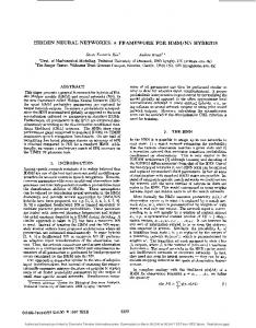
a) Fig. 1.
b) a) MFM entities and b)MFM relations
and control functions that can reveal the integration of underlying physical and engineering design concepts into a goaloriented structure. The subsequent presentation of examples for the modeling of typical functions of sustainable generation technologies illustrates that a modeling of sustainable energy systems is possible in the same framework. At first the modeling will follow a textbook description of frequency control, extending on results of an earlier paper by the authors [10]; further operational practices are modeled according to the Operation Handbook of the UCTE system1 . In a next step, the model is extended to represent the special roles of uncontrollable generation and controllable demand. The result is a top-down, multi-level decomposition of power systems in terms of control objectives and means for their achievement. In a final discussion, the role of markets in the integration of control structures constituted by independent entities is analyzed with a means-ends point of view. II. M ULTILEVEL F LOW M ODELING Multilevel Flow Modeling (MFM) is an approach to modeling goals and functions of complex industrial processes involving interactions between flows of mass, energy and information [11]–[16]. MFM has been developed to support functional modeling [17] of complex dynamic processes and combines means-end analysis with whole-part decompositions to describe the functions of the process under study and to enable modeling at different levels of abstraction. 1 Using P1: Load Frequency Control and Performance, and P2: Accounting and Scheduling, as well as the appendices A1 and A2. Available at http: //www.ucte.org/resources/publications/ophandbook/
2
In MFM, process functions are represented by elementary flow functions interconnected to form flow structures with a common flow object (energy or mass). Connections between functions within flow structures can be assigned with causal roles, indicating the assignment of an active or passive participation in the transport of the flow object. Each flow structure represents a particular goal-oriented view of the system (Figure 1a)). Objectives can be combined with elementary control functions to form control flow structures. Flow structures are interconnected in a multilevel representation through meansend relations, and control relations (Figure 1b)). MFM is founded on fundamental concepts of action [15] and each of the elementary flow and control functions can be seen as instances of more generic action types. The views represented by the flow structures, functions, objectives and their interrelations comprise together a comprehensive model of the functional organization of the system represented as a hypergraph. It should be noted that MFM is a formalized conceptual model of the system which supports qualitative reasoning about control situations [18], [19]. MFM has been used to represent a variety of complex dynamic processes including fossil and nuclear power generation [20]–[22] and several kinds of chemical processes (e.g. [23]). Application of MFM includes model based situation assessment and decision support for control room operators [24], hazop analysis [25], alarm design [26], alarm filtering [27] and planning of control actions [20], [28]. MFM is supported by knowledge based tools for model building and reasoning [16]. Application of MFM in power systems is envisioned to further intelligent agent solutions in power systems control. MFM models could support situation-awareness of agents, for example to enable reasoning about appropriate responses in fault situations [29]. It has been shown in a previous paper by the authors that the capability of representing control is essential for capturing the functional complexity of power systems [10]. Here we extend the results from the previous paper to control areas and expose some first alterations that enable to represent modern sustainable energy ressources. III. P OWER S YSTEM O BJECTIVES , VALUES AND M EANS Energy systems are a means to the end of supplying and distributing energy to all members of society. We value energy being permanently available and thus the main objective of power systems ought to be the reliable supply of electrical energy; today most would agree, that this objective should be pursued with due respect for future generations and not at all costs. We say it should be sustainable and economical. As an entry point for the later analysis it is important to clarify our understanding of values, goals/objectives and the different categories of means. A goal states the intention associated with a system2 . Values are valid without a given system context and they generally qualify goals. The attributes “reliable”, “economical” and “sustainable” further qualify the way in which the means 2 In MFM, goals and objectives are distinguished: Goals are more general, rather value-driven, whereas objectives are more formal, rather process-driven.
IEEE PES/IAS CONFERENCE ON SUSTAINABLE ALTERNATIVE ENERGY, VALENCIA, 2009,
(power system) should be organized3 . These attributes relate to values that are associated with our energy supply. These values may be generalized to (1) Security of Supply, (2) Resource Efficiency and (3) Sustainability [10]. On the one hand, a power system is a technical infrastructure, dealing mostly with a very specific form of electric energy. On the other hand, because it provides fundamental services to society, the system also reflects the values its users associate with their energy supply. Means as analyzed in the context of MFM are functional means – a function is the role of an entity in an action directed at an intentional change of a systems’s state. Generally, means are actions or things used to achieve an end. Means are therefore naturally fitted for specific types of purposes, which means that one could talk about categories of means by purpose: - electric technology means: grid, generators, active / reactive power, control, supervision, system balancing, ... - information technology means: networks, protocols, software agents, ... - control means: measurement, actuation and decisionmaking equipment. - economical means: markets, bids, money value, ... The means of electric technology come to define the structure of the electricity systems. It is typical, that the general objective and the values get into the background in the process of technology development, sometimes due to a lack of appropriate decision making tools. It can be observed that “reliability” is often evaluated and implemented directly by the technologists with a focus on the secure operation of the system power system. Economical means are used to coordinate efficient use of resources. One may add another category of means: Means of sustainability (evaluation), such as “life-cycle analysis” (LCA). However, any modeling approach that focuses on one particular type of means tends to give an incomplete view of the overall workings (interactions) of a system. An actionbased perspective reveals, that in fact all means of technology, economy and control are intertwined on virtually all levels of decomposition. We see functional modelling as a tool that can reflect and expose the complex entanglement of these means. IV. MFM M ODEL OF S TANDARD F REQUENCY C ONTROL In this section we formalize the existing operation and control paradigms of power systems. The control functions presented here are known and well described in the literature [30]–[32]. This formal understanding may lend itself to a number of uses, including the types of applications stated in Section II, such as situation awareness in disturbance situations or automatic planning of control actions for intelligent agents. The most abstract view of the multilevel flow model is shown in Figure 2. The symbols used in this diagram are 3 Other
attributes often stated include: competitiveness, CO2 -reduction, wind-integration, etc. These qualifiers are overly specific and may well reflect a lock-in to typical and existing solutions.
3
Fig. 2. Abstract view of the electrical energy system (MFM model). Here, “Generation follows demand” is logically represented by the assignment of causal roles. The passive causal role of “Generation” is enabled by frequency control.
introduced in Figure 1. The energy system is here described by an energy flow structure S1 , describing a process view, and its association with a goal g1 : Satisfy energy demand. Flow structure and goal are connected by a means-end relation: produce, which expresses that this goal is to be achieved by the system. S1 comprises three energy flow functions: An energy source called “Generation”, a transport function called “Delivery”, and an energy sink called “Demand”. These elements represent basic function types: be a source (provide), transport and be a sink (consume). The flow functions are interconnected by causal relations. A box or arrow at a transport function indicates the causal roles of a connected function. An arrow shows the “agent” role, i.e. the capability of causing a state change in the transport function; a box means (passive) partication. In Figure 2 “Generation” is a passive participant or sender, supplying energy to the transport function, whereas Demand is an agent influencing the energy flow. These causal roles imply that generation is supposed to be following the load demand. This causal role is enabled by the frequency control functions that will be analyzed below. The transport function in S1 represents the function of power-delivery at any time. The objective o1 represents the purpose of frequency control. This purpose can be formalized as follows: !
o 1 : PG = PD ,
(1)
where PD is the power consumed by the demand, and PG is the shaft power of the generators. This equation is the statement of intention that is PG shall equal PD (not the other way around). Reading from left to right, this is expressed by ! the exclamation mark (=). Power generation is brought to follow demand (o1 ) by means of frequency control. Frequency control is separated between frequency droop control (primary frequency control) and system balancing (secondary frequency control). This separation is based on a decomposition of (1): PG = −Ksys ∆fsys + Pdisp,t ,
(2)
with ∆fsys = fsys − f0 is the frequency deviation, Ksys = 1 Rsys the system droop constant and Pdisp,t is the total power dispatch by the system balancing function.
IEEE PES/IAS CONFERENCE ON SUSTAINABLE ALTERNATIVE ENERGY, VALENCIA, 2009,
4
The primary frequency controller (S2 (o1a ), o2 ) ensures that the frequency deviation matches the droop setting and power dispatch. From a system perspective, this corresponds to a proportional control input. It does so by means of adjusting the power inflow to the prime mover, PG , the shaft power input to the generators, using control according to the performance criteria specified in o2 . As a result, the frequency reflects the mismatch between demand and dispatched power. The power dispatch is to be adjusted by the system balancing S3 . B. Control Functions: Secondary Frequency Control and Inter-area balancing
Fig. 3.
Goal decomposition of frequency control.
The decomposition leads to the objectives o1a and o1b of droop control and system balancing, respectively. This decomposition of frequency control objectives is shown in Figure 3. Applying control engineering notions, here the system frequency control has been split up into separate proportional and integral controllers. A. Control Functions: Primary Frequency Control Droop control or primary frequency control is necessary for the mitigation of larger short-term deviations in the balance between load and demand. Droop control, as the frequency, is shared within the complete synchronous region of a power system. Frequency droop control is represented by the control flow structure S2 shown in Figure 4.
Fig. 4. MFM model of primary frequency control. Note the different causal role of the energy source: In this view, the energy provided to the system and the energy removed from it may mismatch, which will result in a change of the storage-level in the kinetical energy storage.
The response is coordinated by an adequate setting of the individual generator droop constants, such that a required system droop constant is achieved. The objective is to achieve the droop characteristic: !
o1a : ∆fsys =
1 · (Pdisp,t − PD ) , Ksys
System balancing is aimed at bringing the frequency back to its nominal value by means of adjusting the power dispatch. It is achieved for example by automatic generation control (AGC) on larger generators. From a system perspective, this objective corresponds to integral frequency control. Following (2), the objective o1 , i.e. matching dispatched generation with demand, is equivalent to returning the frequency to its nominal value: !
o1b : fsys = f0 ,
In larger power systems, this system balancing is more complex, as the system is structured further into control areas. A representation of control areas can be developed in MFM by a step-wise expansion of the flow structure in Figure 2. The expansion is shown in Figure 5 for three control areas. The expansion is done in four steps according to MFM transformation rules: (1) expand transport function “delivery” (series connection); (2) split energy-source “Generation” and energy-sink “Demand”, together with associated transport functions by three (parallel connection); (3) re-order into pairs of “Generation” and “Demand”, representing energy sinks and sources in the control areas; (4) expand central energy-balance: This expansion accounts for the definition of exchange across the border of control areas; the bi-directional transport function is new in MFM. The result of the expansion represents the same causal structure as in Figure 2, but already accounts for the definition of the boundaries of control areas. The purpose of control areas is to balance a mismatch between scheduled demand and supply within the area. This control objective constrains the possible flows, and thus changes the causation of the flow structure. In the abstract model (Figure 6), this is represented by a limitation of the transport function which serves as an agent causing the limitation to the scheduled exchanges for each area. Therefore, the objective of area control is to return its power exchange with other regions to the scheduled values. In the UCTE this is done by the so-called network characteristic method [32]. This method defines an area control error (ACE) for each area (ACEi ) that is to be returned to zero by the area-controller. !
(3)
(4)
o1b,Ai : 0 = ACEi = Pmeas,i − PCP,i + Kri (fsys − f0 ) , (5)
IEEE PES/IAS CONFERENCE ON SUSTAINABLE ALTERNATIVE ENERGY, VALENCIA, 2009,
5
Fig. 6. Abstract MFM model of the system balancing with control areas indicating causal relations. Boxes and arrows at transport functions indicate the causal roles of the respective connected function in the transport-action. An arrow refers to the “agent” role, causing a state change; a box means (passive) partication.
such requirements stated in the UCTE Operations Handbook [32] and must assume that these requirements are implicit knowledge. It has been shown in a formal model, how the original integral control is enhanced to a distributed control method.
Fig. 5. Expansion of energy system flow structure (S1 in Figure 2) to represent three control areas.
here the “K-factor” Kr,i is the area’s primary frequency control contribution, corrected by a “self-regulating effect” of the area (e.g. 1%). Note that the network characteristic method is used to decouple the objectives of the primary and the secondary control, which is necessary because they belong to the same “control loop”. Yet, this decoupling is only static and the two control functions should also be decoupled dynamically, such that the control functions do not disturb each other. That is, in addition to the static decoupling objectives, an additional “performance requirement” needs to be established in order to fully decouple those control functions. The MFM model in Figure 7 shows the cascaded control flow of primary and secondary (area) frequency control. The above mentioned performance requirements would be stated in o2,Ai and in o3,Ai , respecectively. The author could not find
Fig. 7. Control hierachy and flow structure of the system balancing with control areas.
IEEE PES/IAS CONFERENCE ON SUSTAINABLE ALTERNATIVE ENERGY, VALENCIA, 2009,
6
V. N EW ROLES IN P RESENT AND F UTURE S USTAINABLE E NERGY S YSTEMS The analysis above gives a compact illustration of the present control architecture of power systems. In the following we will demonstrate how MFM also can help defining the functions and aggregations of new and distributed energy resources. A. Uncontrollable Generation and Controllable Demand The models developed above are based on the background assumption that generation at large is controllable (and controlled) and that demand is uncontrolled (and uncontrollable); i.e. system imbalances in normal operation are caused by demand. This corresponds to the textbook perspective on power system control. Nevertheless, the performamnce criterion for frequency control is given by a design-disturbance, which typically determined by the N-1 criterium. So for disturbed operation, in fact the performance requirements are also guided by the size of the generators in operation. Most types of renewable electricity generation do not fit this classic picture, as their energy-output is not controlled4 . One of the central measures for the integration of renewable energy is the introduction of controllable demand. Just as controllable generation this measure increases the adjustable range of power flows. Figure 8 shows how the basic energy flow structure of Figure 2 is to be expanded for a representation of additional disturbance and controllability in a modern power system with uncontrolled renewable power generation and controllable demand units. The functional representation of controllable generation and controllable demand shows on one hand how both can be similar with regard to operation; on the other hand it shows also that this similarity only holds for one property of the function.
Fig. 8. Expansion of the abstract view to represent additionally controlled demand and uncontrolled generation. Step (1): expansion of transport function (series connection); step (2a): split both energy-source “Generation” and energy-sink “Demand”, together with associated transport functions in two; step (2b): modify the causal roles to represent uncontrolled generation and controlled demand.
B. Abstract functional representation of co-generation An interesting case that also illustrates the relevance of causal roles can be found for co-generation. A co-generation plant can in principle be run in two control modes: a) Production driven by heat demand, and b) production driven by electricity demand (e.g. when sufficient heat storage is available). Typically, it is possible to run the same plant in one mode or the other. The MFM model in Figure 9 shows the implication of these two control modes for the causal structure of this system. These representations may contain valuable information for decision support systems. The notion of control modes introduces a welcome ambuiguity to the functional models. A unit’s functional representation should always reflect its capabilities. Another example 4 Note the distinction between “controllable” and “controlled”. The functional model describes which role is assumed in a given operational timeframe. Thus, it may be the case for modern wind turbines to provide a controllable active power output range - in this case they would be aggregated under “controlled” instead of “uncontrolled” generation
Fig. 9. This view represents a functional model of a co-generation plant (e.g. Micro-CHP).
for this situation: “uncontrollable generation”, such as modern wind turbines, may well provide a limited controllability, for example for for short term balancing. In this case, the functional representation can be adapted for this particular control mode. VI. D ISCUSSION With the results presented above a new modeling approach has been demonstrated in application to power system. Functional modeling has potential in the modeling of a much
IEEE PES/IAS CONFERENCE ON SUSTAINABLE ALTERNATIVE ENERGY, VALENCIA, 2009,
7
wider range of promising application fields. In the following we discuss the possibility of applying functional modeling supåported by MFM in two specific areas of difficulty: a) economic deregulation: representation of controllable and uncontrollable generation in power markets b) decentralized generation and “aggregation” of control functions A. Decomposition of Control Functions into Market Entities and Exchanged Services In a market place people meet to exchange goods for money. One can say that a market place is established where at least one seller offers a good of his own, one or more buyers are interested in (value) that good and all share a common means of valuation (money). A deal is made when ownership of money and the good are mutually exchanged between the two market entities, typically under the condition that the goodvaluation of the buyer meets or exceeds the good-valuation of the seller. We talk about “buyer” and “seller” because of the role each individual assumes in the market place. In fact, roles are defined through the market exchange process, not through the individuals taking part in this process. Yet, the requirement that a good can be exchanged may depend on more than just the notions of ownership and money. Often a number of mutual requirements need to be fulfilled before a deal can be made. For example a market place traditionally provides support functions to ensure safety and simplicity of deals. Further properties of both seller and buyer may be required to enable the exchange of a specific commodity. This corresponds to the difficulty in defining service agreements: If the good exchanged is not naturally self defined (a piece of something, or subject to a common standard), then buyer and seller need to agree on a definition of the service being provided. “Energy” would be a relatively simple commodity, but it requires a specification of the energy carrier. If the carrier is coal, the good is nearly self-defined (a piece of something). If it is electricity though, the specifics of the system function (e.g. the lack of storage) require a strong definition of requirements: the power system as the “exchange system” requires a cooperative approach to reliability in order to establish the system function that is necessary for the energy exchange. In MFM, entities are related to the realization of a function. That is, a flow structure captures the functional composition of a system, not its realization; a flow structure or a single function may be associated with a physical entity or a virtual aggregation of many. On the other hand, any entity can have one or several functional self-representations. That is a selfrepresentation of its functions would enable a self-interested entity to identify requirements when providing and accepting external functions (services). To illustrate the idea using MFM, Figure 10 shows a simple MFM model of energy exchange between “producer”, “consumer” over an “energy system”. The three basic energy flow structures (source-transport-sink) are interconnected by a “Janus-relation”.
Fig. 10. Sketch of the correspondence between MFM flow structures and market entities. The “Janus-relation” (-J-) establishes a connection between the Producer’s sink and the Generation function, as well as between the Consumer’s source and the Demand function.
The “Janus-relation” (-J-) establishes a connection between complementary functions in different flow structures. The two functions connected by a Janus-relation represent the same functional-entity from different perspectives. For example, an energy-sink is an energy source for another perspective. The two functions share all factual properties, but functional requirements, would be tied to the respective flow structure. Thus the physical realization of the energy-sink of this producer would be identical with the the physical realization of the energy-source of the energy system and the consumer’s energy source is identical with the sink of the energy system. The formulation of requirements instead would be with respect to the respective flow structure. The parallel between the functional (energy) connection of producer, consumer and energy system on one hand, and the their roles with respect to the market operation on the other, is illustrated in Figure 10. As outlined above, there is a potential in formulating such economical relations in the same actiontheoretical framework as the technical functions treated in the remainder of this paper. The roles of the given entities in the commodity-exchange-process are indicated. B. “Functional Aggregation” As shown in Section IV-B and in Figures 5 and 8, MFM provides formal rules that guide the expansion and collapse of flow structures. An expansion of a flow function corresponds to a more detailed view of the functional structure of a system, which led to a neww control opportunity in case of the secondary frequency control. From a bottom-up perspective, an area’s energy source aggregates all generators in the respective area. Detailing and aggregation follows along with new control structures. Aggregation is natural in the representation of functions and it lends itself immediately to formalize aggregation concepts. MFM has been developed as a combination of means-ends and whole-part abstraction levels. Current work on MFM formalizes these different representation and abstraction levels into a flexible data structure. Information models that should integrate information about diverse units require a more abstract formalization of the properties of their subsystems. MFM provides a natural framework to carry and organize such information.
IEEE PES/IAS CONFERENCE ON SUSTAINABLE ALTERNATIVE ENERGY, VALENCIA, 2009,
VII. C ONCLUSION The results in this paper show a further development of MFM toward a promising modeling tool in the application to power systems in the future. Work lying ahead includes a modeling of current modern control concepts such as Microgrids and Virtual Power Plants. R EFERENCES [1] M. D. Ilic, “From hierarchical to open access electric power systems.” Proceedings of the IEEE, Special Issue on "Modeling, Identification, and Control of Large-Scale Dynamical Systems", vol. 95, no. 5, pp. 1060–1084, May 2007. [2] S. D. J. McArthur, E. M. Davidson, V. M. Catterson, A. L. Dimeas, N. D. Hatziargyriou, F. Ponci, and T. Funabashi, “Multi-agent systems for power engineering applications – part I: Concepts, approaches, and technical challenges,” Power Systems, IEEE Trans. on, vol. 22, no. 4, pp. 1743–1752, November 2007. [3] H. Akkermans, J. Schreinemakers, and K. Kok, “Microeconomic distributed control: Theory and application of multi-agent electronic markets,” CRIS, Tech. Rep., 2004. [4] D. Pudjianto, C. Ramsay, and G. Strbac, “Virtual power plant and system integration of distributed energy resources,” IET Renew. Power Gener., vol. 1, no. 1, pp. 10–16, 2007. [5] M. Braun, “Technological control capabilities of DER to provide future ancillary services,” Distr. Energy Resources, Int. Journ. of, vol. 3, pp. 191–206, 2007. [6] M. Braun and P. Strauss, “A review on aggregation approaches of controllable distributed energy units in electrical power systems,” Distr. Energy Resources, Int. Journ. of, vol. 4, no. 4, pp. 297–319, 2008. [7] M. Lind, T. Ackermann, P. Bach, H. W. Bindner, Y. Chen, R. GarciaValle, M. Gordon, K. Heussen, P. Nyeng, A. Saleem, P. E. Sørensen, M. Togeby, I. Vlachogiannis, S. You, and Z. Xu, “Ecogrid.dk phase I WP2 report - system architecture,” Energinet.dk, Tech. Rep., 2008. [8] I. Kamphuis, J. Kok, C. Warmer, and M. Hommelberg, “Architectures for novel energy infrastructures: Multi-agent based coordination patterns,” in IEEE-NGI, Rotterdam, The Netherlands. ECN, 10-12 November 2008, presented, paper available at http://www.ecn.nl/publications/. [9] O. Gehrke, “Infrastructures for power system integration and control of small distributed energy resources,” Ph.D. dissertation, Technical University of Denmark, 2009, forthcoming. [10] K. Heussen, A. Saleem, and M. Lind, “Control architecture of power systems: Modeling of purpose and function,” in Proceedings of the IEEE PES General Meeting 2009, 2009. [11] M. Lind, “The use of flow models for design of plant operating procedures,” in Proc. IWG/NPPCI Specialist meeting on procedures and systems for assisting an operator in normal and anomalous nuclear power plant operation situations, Garching, Federal Republic of Germany, December 1979. [12] ——, “The use of flow models for automated plant diagnosis,” in Human Detection and Diagnosis of System Failures, J. Rasmussen and W. B. Rouse, Eds. Plenum Press, New York, 1981. [13] ——, “Modeling goals and functions of complex industrial plant,” Applied Artificial Intelligence, vol. 8, no. 2, pp. 259–283, 1994. [14] ——, “Plant modeling for human supervisory control,” Transactions of the Institute of Measurement and Control, vol. 21, no. 4-5, pp. 171–180, 1999. [15] ——, “Modeling goals and functions of control and safety systems in MFM,” in Proceedings International Workshop on Functional Modeling of EngineeringSystems, Kyoto, Japan, January 25 2005, pp. 1–7. [16] ——, “Perspectives on multilevel flow modeling,” in Proc. 4.th International Symposium on Cognitive System Engineering Approach to Power Plant Control (CSEPC2008), Harbin, Heilongjiang China, September 8-10 2008. [17] ——, “The what, why and how of functional modelling,” in Proceedings of International Symposium on Symbiotic Nuclear Power Systems for the 21’st Century (ISSNP), Tsuruga, Japan, July 9-11 2007, pp. 174–179. [18] ——, “Status and challenges of intelligent plant control,” Annual Review of Control, vol. 20, pp. 23–41, 1996. [19] A. Saleem, T. Us, and M. Lind, “Means-end based functional modeling for intelligent control: Modeling and experiments with an industrial heat pump,” in Proc. IASTED conference on Intelligent Control Systems (ICS2007), Cambridge, Massachussets, USA, Nivember 21-23 2007.
8
[20] M. N. Larsen, “Deriving action sequences for start-up using multilevel flow models,” Ph.D. dissertation, Department of Automation, Technical University of Denmark, 1993. [21] J. Ouyang, M. Yang, H. Yoshikawa, Y. Zhou, and J. Liu, “Alarm Analysis and Supervisory Control Plan of PWR Plant,” in Proceedings of CSEPC 2004, Cognitive Systems Engineering in Process Control, Sendai, Japan, Nocember 4-5 2004, pp. 61–68. [22] J. Liu, H. Yoshikawa, and Y. Zhou, “Application of multilevel flow modeling to describe complex processes in a nuclear fuel cycle,” in Proceedings CSEPC 2004 Cognitive Systems Engineering in Process Control, Sendai, Japan, November 4-5 2004, pp. 114–120. [23] A. Gofuku and Y. Tanaka, “Application of Derivation Technique of Possible Counter Actions to an Oil Refinery Plant,” in Proc. 4’th IJCAI Workshop on Engineering Problems for Qualitative Reasoning, Stockholm, 1999, pp. 77–83. [24] J. Petersen, “Situation assessment of complex dynamic systems using MFM,” in Proceedings of 8th. IFAC/IFIP/IFPRS/IEA Symposium on Analysis, Design and Evaluation of Human-Machine Systems, Kassel, Germany, September 18-20 2001, pp. 645–650. [25] N. L. Rossing, M.Lind, N. Jensen, and S. B. Jørgensen, “A goal based methodology for hazop analysis,” in Proc. 4.th International Symposium on Cognitive System Engineering Approach to Power Plant Control (CSEPC2008), Harbin, Heilongjiang, China, September 8-10 2008. [26] T. Us, N. Jensen, M. Lind, and S. B. Jørgensen, “Fundamental principles of alarm design,” in Proc. 4.th International Symposium on Cognitive System Engineering Approach to Power Plant Control (CSEPC2008), Harbin, Heilongjiang China, September 8-10 2008. [27] J. E. Larsson, “Diagnosis based on explicit means-end models.” Artificial Intelligence, vol. 80(1), pp. 29–93, 1996. [28] A. Gofuku and Y. Tanaka, “Development of an Operator Advisory System: Finding Possible Counter Actions in Anomalous Situations,” in Proc. 5’th International Workshop on Functional Modeling of Complex Technical Systems, Paris, France, July 1-3 1997, pp. 87–97. [29] A. Saleem, K. Heussen, and M. Lind, “Agent services for situation aware control of electric power systems with distributed generation,” in Proceedings of the IEEE PES General Meeting 2009, 2009. [30] P. Kundur, Power System Stability and Control, EPRI, Ed. McGrawHill, Inc., 1994. [31] A. J. Wood and B. F. Wollenberg, Power generation, operation, and control. John Wiley & Sons, 1996. [32] UCTE Operation Handbook: P1 - Load Frequency Control and Performance, 2nd ed., "Union for the Co-ordination of Transmission of Electricity" (UCTE), 2004, available at http://www.ucte.org/resources/ publications/ophandbook/.
Kai Heussen (M’07) is currently a Ph.D. student in Automation and Electric Energy Systems at the Department of Electrical Engineering at the Technical University of Denmark. He studied control engineering in Stuttgart and Toronto and received his degree of Engineering Cybernetics from the University of Stuttgart in 2007. His research interests include control theory, distributed control architecture and the design of integrated energy sytems with very high shares of renewable energy.
Morten Lind is Professor of Automation at Department of Electrical Engineering at Technical University of Denmark and is associated Centre for Electric Technology. His research interests include automation design, supervisory control of complex industrial systems and infrastructures, and application of agent technology and knowledge based system in automation.