Decoupled control of Modular Multilevel Converters using Voltage ...
Recommend Documents
Oct 26, 2017 - (4) With pulse-width modulation (PWM): great loss of power in the ... first commercially used in the Trans Bay Cable project in San Francisco [16]. The article ...... that can be connected to each feeder depends on the submarine.
(MPC), modular multilevel converter (M2LC), voltage balancing. I. INTRODUCTION ..... The definitions of the system matrices Ai, Bi, V i, Ci, Ac,. Bc, and Cc can ...
on estimation of the stored energy in the arms by combining the converter electromotive force reference, the measured alternat- ing output current, and the ...
Feb 17, 2012 - topology when used as an acâac converter is the input and output frequency components in the control loop, resulting in a more com-.
Abstractâ Low Voltage Ride Through (LVRT) is an important grid requirement for Voltage Source Converter (VSC) based. HVDC links. This paper studies the ...
Modular Multilevel Converters - MDPI › 59f37a94a6fdcc075ec348b1 › M... › 59f37a94a6fdcc075ec348b1 › M...by F Martinez-Rodrigo · 2017 · Cited by 43 · Related articlesOct 26, 2017 — applications in high voltage direct current (HVDC) transmission alo
reverse voltage âVdc can be obtained by turning on S2 and S3 at the same time, whereas S1 and S4 ..... 12 Three-port UNIFLEX-PM system based on CHB.
Jan 17, 2014 - Introduction. Motivation for Dissertation Research. Generalized Predictive Control of Multilevel Diode-Clamped. Converters. Predictive Current ...
Multilevel power conversion was first introduced 20 years ago [1]. The general concept involves utilizing a higher number of active semiconductor switches to ...
required DC voltage level number to reduce the hardware cost. A. 17-level example was implemented with an 11-level H-bridge multilevel converter and an 8µs ...
in the AC side of the converter. Several operation modes, including asymmetric monopole, are presented and their sizing requirements are discussed.
Modular multilevel converters (MMC) are gradually becoming the technology of choice in ..... Carrier wave-form rotation for phase disposition PWM - 3 levels. 85.
Sep 17, 2014 - taneous Power Theory, Voltage Source Converter (VSC), Grid- ... A. Hably is with the Grenoble Image Parole Signal Automatique Labora-.
proof reading, and general advice during the preparation of the thesis. ... 2, p. 1028-1032. G. M. Lindgren, J. Svensson, "Control of a Voltage-source Converter Connected to the ...... Figure 10: Line to line voltage pulse using a 20 meter cable.
In this paper, the Cascaded H-Bridge (CHB) converter is compared to the Modular Multilevel Converter (M2LC) re- garding their efficiency and use of active and ...
controllability, black-start capability and islanded operation [1]. Also, unlike LCC-HVDC, it does not require voltage polarity reversal to change the direction of the ...
Converters for Industrial Medium-Voltage Drives. Dietmar Krug, Steffen ... source
converters: two- level voltage source converters (2L-VSCs; e.g., Converteam),.
5) M. Tavakoli Bina, Toosi University of Technology, Iran; ... Engineer, M.Sc., and D.Sc. degrees in electrical engineering from the University of Concepcion,.
Dec 16, 2011 - AbstractâThis paper studies the possibility of building a modu- lar multilevel converter (M2C) using silicon carbide (SiC) switches. The main ...
Sep 15, 2011 - Converters - the Power Transmission. Backbone of the Future. Noman Ahmed1, Staffan Norrga1, Hans-Peter Nee1. 1). Electrical Energy ...
HVDC systems. In recent times, in the power transmission era, for very long distances, high voltage DC. (HVDC) transmission lines based on current source ...
Feb 12, 2014 - converters, the Modular Multilevel Converter (MMC), proposed ten years ago by .... adattabile rispetto ai differenti livelli di tensione e corrente.
International Journal of Power Electronics and Drive System (IJPEDS). Vol. 4, No. 1, March 2014 pp. ... interesting area for the application of MMIs. This paper is ...
Decoupled control of Modular Multilevel Converters using Voltage ...
to high-voltage applications but Modular multilevel converter. (M2LC) is ... Zealand (email: bria001@aucklanduni.ac.nz, u.madawala@auckland.ac.nz).
Decoupled control of Modular Multilevel Converters using Voltage Correcting Modules Baljit S. Riar, and Udaya K. Madawala B. S. Riar and U. K. Madawala are with the Department of Electrical and Computer Engineering, The University of Auckland, 1052 Auckland, New Zealand (email: [email protected], [email protected]).
c 2014 IEEE
IEEE Transactions on Power Electronics, Early Access. DOI:10.1109/TPEL.2014.2313613 Personal use of this material is permitted. Permission from IEEE must be obtained for all other uses, in any current or future media, including reprinting/republishing this material for advertising or promotional purposes, creating new collective works, for resale or redistribution to servers or lists, or reuse of any copyrighted component of this work in other works. Permission to use this material must be obtained from the IEEE by sending a request to [email protected].
1
Decoupled control of Modular Multilevel Converters using Voltage Correcting Modules Baljit S. Riar, Student Member, IEEE, and Udaya K. Madawala, Senior Member, IEEE
B. S. Riar and U. K. Madawala are with the Department of Electrical and Computer Engineering, The University of Auckland, 1052 Auckland, New Zealand (email: [email protected], [email protected]).
ibT VCMbT
VCMcT
icT
Ma1
Mb1
Mc1
Srn,1 irm
Vdc
MaN
McN
R
MbN R
L
L
R L
L
L R
L R
R Ma(N+1)
Mb(N+1)
Mc(N+1)
Ma2N
Mb2N
Mc2N
VCMaB iaB
VCMbB ibB
VCMcB icB
Vrn
VCM,rm S2,rm
ib
ic
Rl
Rl
Ll
Ll
Ll
Vg,a
Vg,b
Vg,c
+ -
Srn,2
S1,rm irm
Rl
ia
C
Vc,rn
iaT VCMaT
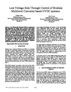
Fig. 1: Proposed topology (M2LC-VCM)
S3,rm
S4,rm
+ -
Vvcm,rm
idc
Cvcm
Modular multilevel converter (M2LC) topology, which features modularity, scalability, reduced voltage rating of the switches and redundant switching operations, has recently become popular in medium to high voltage applications [1]– [3]. A number of advantages associated with these features make M2LC suitable for a variety of applications, such as high-voltage direct current (HVDC) transmission [4], [5], motor drives [6], traction motors [7] and static synchronous compensator (STATCOM) [8]. There are, however, disadvantages associated with the topology, which include the need for both balancing capacitor voltages and controlling circulating currents, and the increased complexity of the overall control scheme [9]. Sorting algorithms, which are based on the polarity of arm current, have commonly been used to balance capacitor voltages [1]. Circulating currents are inherent to the M2LC topology and manifest from the variations in capacitor voltages and in combination with the modulation scheme [2], [10]. These currents do not affect the load current, but cause variations in capacitor voltages while increasing converter losses. Various methods, both hardware and control based, have been proposed to minimize circulating currents. In [11], each
icir,c
I. I NTRODUCTION
icir,b
Index Terms—Circulating currents, modular multilevel converter (M2LC), voltage balancing, voltage correcting module (VCM), HVDC, decoupled control.
phase-leg incorporates a filter that is tuned to block second harmonic of the circulating current. In situations where the number of modules is increased without changing the number of voltage levels, active redundancies of the modules have been used to reduce the capacitor voltage variations and circulating currents [12]. In [13], capacitor voltages have been maintained within tight bounds around the nominal value to control the circulating currents. Model predictive direct current control scheme has also been adopted to control the currents [14], [15]. In contrast, circulating currents have been minimized by employing cascaded control loops, during which the modulation index of each arm or module is modified [6], [16]–[19]. Furthermore, currents can also be minimized by adding a common-mode voltage term to the reference of the arm voltages [20], [21]. This paper presents a modular multilevel converter topology that employs voltage correcting modules (M2LC-VCM), as shown in Fig. 1, to minimize circulating currents while reducing the complexity of control. In the proposed topology, one full-bridge voltage correcting module (VCM), which has a lower voltage rating than a half-bridge module, is included in each arm of the converter to minimize circulating currents
icir,a
Abstract—Historically, cascaded H-bridge, capacitor clamped and neutral point clamped topologies have been used for medium to high-voltage applications but Modular multilevel converter (M2LC) is becoming a popular alternative. However, in comparison to other topologies, control of load current, which is inherently coupled with circulating currents, is more difficult in the M2LC topology. This paper proposes a modified M2LC topology that allows for decoupled control of circulating currents from load current. Each arm of the modified topology comprises a plurality of half-bridge modules and one full-bridge module. The full-bridge module minimizes harmonic currents within the converter without affecting the load current. A state-space model, which is generalized per arm with an N number of half-bridge modules and one full-bridge module, is presented to accurately predict the behaviour of the proposed topology. Theoretical as well as experimental results of a single-phase threelevel 800-VA prototype converter are presented with a discussion to demonstrate the viability of both the proposed mathematical model and modified topology. A comparative investigation with respect to a conventional topology reveals that the proposed topology offers superior performance.
2
[3]. The VCM can be considered as an active filter, which minimizes harmonic currents within the converter. The M2LCVCM allows for decoupled control of load and circulating currents, where the load current is controlled by the half-bridge modules and the circulating current is controlled by the fullbridge modules. A generalized state-space model is presented to accurately characterize the dynamic behaviour of the proposed M2LC-VCM topology. Theoretical results are presented in comparison to experimental results of a single-phase threelevel 800-VA prototype M2LC converter to demonstrate the accuracy of the model and validate the proposed decoupled control philosophy. Results clearly indicate that the circulating currents can significantly be reduced even when the switching frequency is equal to the fundamental frequency of the load current.
between them then the dc value of the circulating current in a phase-leg is given by: icir,r =
idc Vph iph cos(φ) = 3 Vdc
(3)
The harmonic currents are inherent to the M2LC topology and manifest from the variations in capacitor voltages in combination with the modulation scheme [10]. This relationship between the circulating current, modulation scheme, capacitor voltages and VCMs can be represented mathematically, using the equivalent circuit of the proposed topology in Fig. 2. The power-modules are represented as a controllable voltage source, Vrm , as given by (4) and (5) VrT =
II. P ROPOSED M2LC WITH VOLTAGE CORRECTING MODULES (M2LC-VCM S )
VrB =
N X
urn Vc,rn
n=1 2N X
(4)
urn Vc,rn
(5)
n=N +1
A. Configuration Fig. 1 shows the proposed M2LC-VCM topology. Each arm consists of N half-bridge modules, which are represented as Mrn , r ∈ {a, b, c}, n ∈ {1, 2, . . . 2N }, a resistor, R, that models conduction losses and an arm inductor, L. The individual half-bridge module has two switching states urn ∈ {0, 1}. State 1 corresponds to switch Srn,1 is on, connecting the capacitor in the circuit. Generally, the M2LC is driven in a manner that N half-bridge modules are connected in series across the dc-link and capacitor voltages, Vc,rn , are balanced around VNdc , which results in at least 2N + 1 line-line voltage levels. The proposed M2LC-VCM has at-least one VCM in each arm to control the circulating currents. The VCM has three switching states uvcm,rm ∈ {−1, 0, 1}, m ∈ {T, B}, which are associated with the polarity of the VCM output voltage, VCM,rm . Hereafter, the half-bridge modules and fullbridge modules are termed as power-modules and voltage correcting modules (VCMs), respectively. B. Circulating Currents
VCMs are represented as VCM,rm in the equivalent circuit and the mid-point of the dc-link voltage is used as the reference voltage. The output voltage of the converter, Vr , arm current, irm , and the voltages of the VCMs, VCM,rm , and power-modules, Vrm , can be related as follows: dirT Vdc − VrT − VCM,rT − Vr = RirT + L 2 dt Vdc dirB − VrB − VCM,rB + Vr = RirB + L 2 dt
dicir,r + 2Ricir,r = (Vdc − VrT − VrB ) − (VCM,rT + VCM,rB ) dt (8) It is clear from (8) that harmonics in the circulating currents can be controlled through the voltage that is injected by VCMs, (VCM,rT + VCM,rB ). Subtracting (6) from (7) the output voltage
2L
idc
∞
X irB irT ih,r + = icir,r + 2 2
iaT VaT
ibT VbT
icT VcT
VCM,bT
VCM,cT
(1)
h=1
Vdc/2
The circulating currents consist of a dc, icir,r , and harmonic, ih,r , current components [10]. The dc component of the current is in proportion to the power delivered or load current. For a three-phase system, the input and output power are related as follows: (2)
where, Vdc and idc are the dc-link voltage and current, respectively. φ denotes the phase angle between the phase-voltage, Vph , and phase-current, iph . If circuit parameters of all the three phase-legs are symmetrical and there is a uniform power flow
VCM,aT R
R
L
L
Vdc
Va
L R Vdc/2
Vdc idc = 3Vph iph cos(φ)
(7)
Adding (6) and (7), and using (1), the relationship between the circulating currents and various voltages in a phase-leg can be established as
The circulating current in a phase-leg is related to arm currents as follows: icir,r =
VCMs have only minor impact on the output voltage due to two reasons. Firstly, as described in the forthcoming section, the magnitude of the voltage inserted by each VCM is smaller than the voltage-step of the output voltage. Secondly, VCMs are controlled in a manner that the inserted voltages are equal in respective arms. Therefore, the voltage difference, (VCM,rB − VCM,rT )/2, in (9) is almost zero. III. M ATHEMATICAL MODEL
x = [iaT iaB ibT ibB idc Vg,α Vg,β Vc,a1 Vc,a2 . . . Vc,c2N Vvcm,aT Vvcm,aB . . . Vvcm,cB ]⊤ (10) The input vector is denoted as follows: u = [ua1 ua2 . . . uc2N uvcm,aT uvcm,aB . . . uvcm,cB ]⊤ (11) where urn ∈ {0, 1} is the switching state of a power-module and uvcm,rm ∈ {−1, 0, 1} is the switching state of a VCM. The complete system can be expressed in the standard statespace form as: dx = Ax + Bu + V (12) dt The definitions of the system matrices A, B and V are given in the Appendix.
Switching Load current pulses control $UP FXUUHQW¶V & polarity Capacitor Capacitor sorting voltages
Circulating current control
Switching pulses Arm current
Vdc
Power Modules
VCMs
VCM capacitor voltages
+
ir
Loop 2 Load
Fig. 3: Block digram of the decoupled control scheme
+
1/2 iaB
P _
+
1/2 icir,ref +
Vvcm,aT PI
_
+ +
+
VCMRef,aT
(+) if iaT • 0 (-) if iaT < 0
Vvcm,ref
Vvcm,aB _
State-space model is derived by using a M2LC-VCM topology with N power-modules and one VCM in an arm. Statevariables of the model, where the load is connected in starconfiguration, are the arm currents in phases a and b, dc-link current, grid voltages in the alpha/beta coordinate system and capacitor voltages of the power-modules and VCMs. The statevector of the model is defined as:
Loop 1
iaT
+
+ PI
+ +
VCMRef,aB
(+) if iaB • 0 (-) if iaB < 0 Fig. 4: Control of VCMs in phase-leg a
IV. D ECOUPLED CONTROL
OF THE
M2LC USING VCM S
The control scheme for driving the switches of powermodules and VCMs is split into two concurrent loops, which are labelled as loop 1 and loop 2 in Fig. 3. The first loop, loop 1, controls the load current and determines a switching pattern to balance the capacitor voltages. Control schemes, such as Stair-Case Modulation (SCM) and Optimized Pulse Patterns (OPPs) [16], [22], are appropriate for reducing the switching frequency for a given load current distortion and can also be part of this loop. The number of power-modules, which are connected in an arm, controls the load-current, whereas selection of these modules balances the capacitor voltages. The capacitor voltages are balanced by using a simple and commonly used method, the sorting algorithm [1]. With this algorithm, all the capacitor voltage measurements are sorted in either ascending or descending order of their voltage magnitudes and the capacitors are selected to be connected or bypassed. For example, for a positive arm current the capacitors with lowest voltage are selected first, and conversely, the capacitors with the highest voltage are prioritized for a negative arm current. The second loop, loop 2, controls the circulating currents by controlling the VCMs. The circulating currents, as given by (1), consist of a number of harmonics, which can be minimized by inserting an appropriate voltage in accordance with (8). The control scheme of the VCMs, as shown in Fig. 4 for phase-leg a, controls the circulating currents and maintains the capacitor voltage of each VCM at its nominal value. In each phase-leg, the circulating current is compared with a reference, icir,ref = i3dc , and then proportional (P) controller is used to generate a voltage reference of the VCM modules. This voltage reference is equally divided and added to reference of the top and bottom VCM in a phase-leg to minimize the effect of VCMs on the output voltage, (9). A proportional-integral (PI) controller is used to regulate the capacitor voltage of the VCM module at its nominal value,
4
Vvcm,ref . The output of the PI controller is multiplied with a sign function that is based on the polarity of the arm current. For a positive arm current the sign is positive and vice versa. Finally, the voltage references, VCMRef,rm , are compared against carrier waveforms to generate pulse patterns for switches S1,rm – S4,rm . The VCMs do not excessively increase the switching losses even when their switching frequency is higher than the powermodules, because of the lower voltage ratings. With the higher switching frequency, bandwidth of the circulating current control loop (loop 2) can be much larger than the load current control loop (loop 1). From the control perspective, the modified topology has two main advantages. Firstly, a simple control scheme can be used to control the load current or output voltage. Secondly, the control of the circulating current is decoupled from the load current. The load current and circulating currents are controlled by the power-modules and VCMs, respectively. Moreover, the output voltage or the number of the output voltage levels of the converter is not affected as explained before.
ibT
iaT
idc
VCMaT
VCMbT
Ma1
Mb1
Ma2
Mb2 Rl
L
Ll
il
L
Vdc L
Vab
L
Ma3
Mb3
Ma4
Mb4
VCMaB
VCMbB
iaB
ibB
(a) Circuit diagram
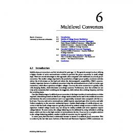
V. R ESULTS A. M2LC-VCM Prototype In order to verify the viability of the proposed topology, a single-phase three-level 800-VA prototype M2LC was constructed. The experimental setup is shown in Fig. 5 and the circuit parameters of the system are summarized in Table I. Base quantities for the p.u. system are Vb = 180 V, Ib = √ 2Irat = 6.15 A and fb = 50 Hz. The control scheme was implemented on a TMS320F28335 Digital Signal Controller (DSC). The DSC has an on-board Analog to Digital Converter (ADC), which was used to measure the arm currents and the capacitor voltages. Altera’s DE2 board was used to generate dead-time for the switching signals of modules and to safely shut down the converter in the unlikely event of a fault. IGBT, IKW20N60H3, and Mosfet, IRFP250MPBF, are used for switches in the power-modules and VCMs, respectively. The use of Mosfets also helps to decrease the effect of deadtime. Moreover, methods discussed in [23] can also be used to compensate the effect of dead-time in each switch. At start-up, a resistor was connected in series with the dcsupply to charge the capacitors and it was bypassed during normal operation of the converter. The diode, as shown in Fig. 5a, is part of the dc-supply that was used in the experiments. The diode also ensures that the dc-current is unidirectional and this feature is congruent with the six-pulse or twelve-pulse TABLE I: Parameters of a single-phase M2LC-VCM setup Parameter Output frequency Supply voltage Load current Power-module capacitance VCM capacitance Load resistance Load inductance Arm inductance Number of modules
f Vdc il C Cvcm Rl Ll L N
SI 50 Hz 280 V 4.35 A 1.72 mF 1.72 mF 40 Ω 30 mH 1.2 mH 2
p.u. 1 1.56 0.71 15.82 15.82 1.37 0.32 0.01
(b) Prototype M2LC Fig. 5: Experimental setup of the M2LC
diode rectifiers that are commonly used in power converter applications. B. Performance Evaluation using PWM Switching of PowerModules Three case studies were considered to experimentally evaluate the performance of the proposed topology and its statespace model. Case I evaluates the performance of the conventional topology, which is used to benchmark the performance of the other cases. In case I, the VCMs as shown in Fig. 5a were bypassed during the experiments. Case II evaluates the performance of the proposed topology. The mathematical model, as presented in section III, was modified to characterise the behaviour of the single-phase M2LC-VCM, as shown in Fig. 5a. Case III was formed to investigate the viability of the modified model. In all cases, pulse patterns of the power-modules were computed offline by comparing a sinusoidal reference with carrier waveforms in phase-disposition. The resulting pulsewidth modulation (PWM) based patterns were stored in a look up table and used for controlling power-modules. With all the cases, the system was operated at its rated conditions as given in Table I. The sorting algorithm, as explained in previous section, was used in all the cases to balance the capacitor voltages. The switching frequency of the power-modules in these three cases was approximately 380 Hz. The control scheme, as described in section IV, was used to control the
5
6.16
Current (A)
3.08 0
−3.08 −6.16 0
20
40 60 Time (ms) (a) Case I
80
100
0
20
40 60 Time (ms) (b) Case II
80
100
0
20
40 60 Time (ms) (c) Case III
80
100
100
0
20
40 60 Time (ms) (c) Case III
80
100
100
0
20
40 60 Time (ms) (c) Case III
80
100
Fig. 6: Arm currents in phase-leg a using PWM
6.16
Current (A)
4.62 3.08 1.54 0 0
20
40 60 Time (ms) (a) Case I
80
100
0
20
40 60 Time (ms) (b) Case II
80
Fig. 7: Dc-link current using PWM
150
Voltage (V)
145 140 135 130
0
20
40 60 Time (ms) (a) Case I
80
100
0
20
40 60 Time (ms) (b) Case II
80
Fig. 8: Capacitor voltages of power-modules in phase-leg a using PWM
VCMs and switching frequency of the VCMs was 2 kHz. Fig. 6 shows the waveforms of the arm currents in phase-leg a. In case I, the second harmonic of the arm current prevails because of a lack of circulating current control. The VCMs reduces the second harmonic of the arm current with the proposed topology, i.e. cases II and III. Relative to case I, the rms arm current is reduced by 3 % with cases II and III. Both analytical (case III) and experimental (case II) waveforms are similar and confirm the validity of the mathematical model. Fig. 7 shows the waveforms of the dc-link current to demonstrate that the ripple in the dc-link current or the harmonic circulating currents are significantly reduced with the proposed topology. In comparison to case I, magnitude of the current ripple is reduced by 65 % and 82.5 % with cases II and III, respectively. It is evident that the VCMs minimize the harmonic circulating currents within the converter.
Fig. 8 shows that capacitor voltages of the power-modules are balanced around their nominal value. The average of the capacitor voltages, which is slightly lower than Vdc /2 = 140V is due to the voltage drop across the various resistors within the converter. Nonetheless, the waveforms with these cases show a similar trend. Capacitor voltages of the VCMs, as shown in Fig. 9, are balanced around an average value of 6 V, which is about 5 % of the voltage across the power-modules. Both analytical and experimental waveforms are similar. Overall, experimental and analytical results are in good agreement both in values and trend, thus validating the accuracy of the model. The small discrepancy in the waveforms is due to a number of factors, such as the model does not consider delays associated with the ADCs and filters. Moreover, the resistive elements that were considered in the
12
6.16
9
4.62 Current (A)
Voltage (V)
6
6 3 0
3.08 1.54
0
20
40 60 Time (ms) (a) Case II
80
100
0
20
40 60 Time (ms) (b) Case III
80
0
100
0
20
40 60 80 Time (ms) (a) Conventional
Fig. 9: Capacitor voltages of VCMs in phase-leg a using PWM
100 0
20
40 60 80 Time (ms) (b) Proposed
100
Fig. 11: DC-link current using SCM
model, as constant losses, were all estimated values and also add to the slight discrepancy in the waveforms.
C. Performance Evaluation using SCM Switching of PowerModules Stair case modulation (SCM) method was used to evaluate the performance of the converter at a lower switching frequency of the power-modules. With this method, the pulse patterns that eliminate the fifth harmonic of the output voltage waveform were generated as described in [23] and used to control power-modules. The experiments were conducted using circuit parameters as listed in Table I. In addition, dclink voltage, Vdc , was reduced to 268 V so that the converter delivers the rated load current with the given patterns. The sorting algorithm was used to balance the capacitor voltages and the control scheme, as described in section IV, was used to control the VCMs. The switching frequency of the powermodules and VCMs was 50 Hz and 2 kHz, respectively. Experimental waveforms of the arm and dc-link currents using SCM are shown in Fig. 10 and Fig. 11, respectively. The rms arm current reduces by 2 % relative to the conventional topology. In comparison to the conventional topology, magnitude of the dc-link current, as shown in Fig. 11, is reduced by 58 %. These results clearly demonstrate that the circulating currents can be reduced even at a lower switching frequency of power-modules. It can be seen from Fig. 12 and Fig. 8 that the reduced switching frequency of the power-modules, however, increases the voltage variations of the capacitor voltages. 6.16
Current (A)
3.08
Voltage (V)
144 139 134 129 124
0
20
40 60 80 Time (ms) (a) Conventional
100
0
20
40 60 80 Time (ms) (b) Proposed
Fig. 12: Capacitor voltages of power-modules in phase-leg a using SCM
VI. I MPROVEMENT IN P ERFORMANCE - A LTERING PARAMETERS The state-space model, which is proven to accurately describe the behaviour of the converter, is further used to evaluate the performance of a grid connected three-phase M2LCVCM. Each arm of the three-phase converter comprises four power-modules and one VCM. The circulating currents or voltage-discrepancy in a phase-leg is a function of circuit parameters [10]. Therefore, the parameters, which result in an increased voltage discrepancy, were selected to investigate the performance of the proposed topology. The parameters of p 2/3V the system are summarized in Table II using V = ll = b √ 2449.49 V, Ib = 2Irat = 516.19 A and fb = 50 Hz as base quantities for the p.u. system. A vector control (VC) scheme with PWM, where carrier waveforms at 750 Hz were in phase disposition, was used to control the rated load current at unity power factor. The capacitor voltages were balanced by using the aforementioned sorting algorithm. The VCMs were controlled using the scheme which is described in Sec. IV and switching frequency of the VCMs was 600 Hz. In addition, the average voltage of TABLE II: Parameters of a three-phase M2LC-VCM setup
0
−3.08 −6.16 0
20
40 60 80 Time (ms) (a) Conventional
100 0
20
40 60 80 Time (ms) (b) Proposed
Fig. 10: Arm currents in phase-leg a using SCM
100
100
Parameter Output frequency Supply voltage Grid voltage Load current Power-module capacitance VCM capacitance Load inductance Arm inductance Number of modules
f Vdc Vll ir C Cvcm Ll L N
SI 50 Hz 5.2 kV 3 kV 365 A 5 mF 5 mF 5.23 mH 1.5 mH 4
p.u. 1 2.12 1.22 0.71 7.45 7.45 0.35 0.09
7
516
Current (A)
258 0
with the three-phase setup is greater than the single-phase setup. VCMs of the three-phase setup, therefore, allow for further improvements in performance. Moreover, the results also show that the improvement in performance of the threephase M2LC-VCM is greater than the single-phase M2LCVCM.
−258
VII. D ISCUSSION The circulating currents, which are driven by a small voltage 0 20 40 60 80 100 0 20 40 60 80 100 Time (ms) Time (ms) difference in a phase-leg, can be reduced by increasing the (a) Conventional (b) Proposed size of passive components such as arm inductance, resistance or capacitance of the power-module [10]. Increasing the arm Fig. 13: Dc-link current (solid line) and arm currents in phase-leg a (dashed and dotted lines) resistance, however, will reduce the efficiency of the converter. 300 Increasing the capacitance, where the voltage rating of the capacitor is equal to the step size of the output voltage, could 225 increase the monetary cost and footprint of the converter. Similarly, inductors, which are designed to operate in low 150 frequency range, are bulky and increase the footprint of the converter. As presented in the paper, the circulating currents 75 can also be reduced by the VCMs in a phase-leg. The VCM is an active filter and, unlike the passive components, can adapt 0 0 200 400 600 800 1000 0 200 400 600 800 1000 rapidly to the varying operating conditions of the converter. Frequency (Hz) Frequency (Hz) Dimensioning of the VCM modules can be performed after (a) (b) selecting the capacitance of the power-modules and the arm inFig. 14: Arm current spectrum ductance, where the latter can be selected using the guidelines, such as [24], [25]. The voltage rating of the VCM switches is the VCM capacitors was 3.85 % of the dc-link voltage. In equal to the average voltage of the VCM capacitors and the the following discussion, performance of the M2LC-VCM is voltage is primarily governed by the voltage discrepancy in a compared against the conventional M2LC topology that was phase-leg (8). This discrepancy or the average voltage, which also controlled using the VC scheme. is a function of the circuit parameters, can be determined Fig. 13 shows the waveforms of the arm currents in phase using the state-space model. Consequently, circulating currents a and the dc-link current with the conventional and proposed can only be suppressed if the average voltage of the VCM topology. The rms arm current reduces by more than 16 % capacitor is sufficient to minimize the voltage discrepancy. relative to the conventional topology. The average dc-link Because the arm current flows through the VCM switches, current is unaffected in both the cases, however the ripple current rating of the VCM switches is same as that of the of the dc-link current is slightly reduced with the proposed power-modules. Moreover, variation in the VCM capacitor topology. voltages is a function of VCM capacitance and arm currents. The arm current spectrum is shown in Fig. 14. As expected, The capacitance, which yields an appropriate voltage variation, the second harmonic of the arm and, thus the circulating can also be determined using the model. current, is significantly reduced with the proposed topology. The switching frequency of the VCM depends on the As can be seen from Fig. 14, the fundamental and dc com- frequency of the harmonic currents to be minimized. Typically, ponents of the arm current are not changed which means that frequencies of the most dominant harmonics are 100 Hz the VCMs do not affect the load or the dc-link current. The (second harmonic) and 200 Hz (fourth harmonic). Therefore, control scheme, as presented in section IV, uses a proportional the switching frequency for which VCMs yield an appropriate regulator for controlling the circulating currents. It is evident performance can also be selected using the model. At present, from Fig. 14 that the proportional regulator is unable to 1.5 suppress all the harmonic currents. However, this inherent limitation of the proportional regulator can be overcome by 1.4 using proportional-resonant regulator or by the proportionalintegral scheme as described in [3]. 1.3 Fig. 15 shows the waveforms of the capacitor voltages that are balanced around their nominal value. With the proposed 1.2 topology, the variation in the capacitor voltages is approximately 9 % of the average value, which is one-half of the 1.1 0 20 40 60 80 100 0 20 40 60 80 100 variation with the conventional topology. Time (ms) Time (ms) In general, the rms arm current is a function of the load (a) Conventional (b) Proposed current and circuit parameters [10]. With the choice of circuit Fig. 15: Power-module capacitor voltages in phase-leg a parameters, the ratio of the rms arm current and load current Voltage (kV)
Current (A)
−516
8
no effort has been made to optimize the performance of the converter and the chosen frequency of 2 kHz is not an optimal selection. VIII. C ONCLUSIONS A modular multilevel converter with voltage correcting modules, M2LC-VCM, has been proposed to decouple and simplify the control of the load and circulating currents. The circulating currents are controlled by a full-bridge module which is included in each arm of the converter. A mathematical model has been formulated and used for investigating the performance of the proposed topology. Validity of the proposed concept has been verified both analytically and experimentally using a single-phase three-level 800-VA prototype M2LC-VCM. The experimental results have shown that the M2LC-VCM achieves an appropriate control of the circulating currents even at a lower switching frequency of the half-bridge modules. A PPENDIX The matrices and vectors of the state-space model (12) are given as follows:
1 diag(iaT I N , iaB I N , ibT I N , ibB I N , icT I N , icB I N ) C (24) 1 diag(iaT , iaB , ibT , ibB , icT , icB ) (25) G4 = Cvcm
and 0y is a zero vector of length y. The parameters used in the above equations are the inductance and resistance of both the load and arm, Ll , L, Rl and R, respectively. Moreover, diag(...) is a square diagonal matrix with entries inside the brackets at its main diagonal [ ]. ACKNOWLEDGMENT The authors are grateful to Dr. D. J. Thrimawithana, M. J. Neath and J. Scoltock of The University of Auckland for their advice with the experiment setup and implementation, and financial support of The University of Auckland Doctoral Scholarship. R EFERENCES [1] A. Lesnicar and R. Marquardt, “An innovative modular multilevel converter topology suitable for a wide power range,” in Proc. Power Tech. Conf., 2003, vol. 3, pp. 6 [2] S. Rohner, S. Bernet, M. Hiller and R. Sommer, “Modelling, simulation and analysis of a Modular Multilevel Converter for medium voltage applications,” in Proc. IEEE Int. Conf. Ind. Technol., 2010, pp. 775–782 [3] B. S. Riar, and U. K. Madawala, “A novel Modular Multi-level Converter topology with Voltage Correcting Modules (M2LC-VCMs),” in Proc. IEEE Int. Conf. Ind. Technol., 2013, pp. 451–456 [4] M. M. C. Merlin, T. C. Green, P. D. Mitcheson, D. R. Trainer, R. Critchley, W. Crookes and F. Hassan, “The Alternate Arm Converter: A New Hybrid Multilevel Converter With DC-Fault Blocking Capability,” IEEE Trans. Power Delivery, vol. 29, no. 1, pp. 310-317, Feb. 2014. [5] R. Feldman, M. Tomasini, E. Amankwah, J. C. Clare, P. W. Wheeler, D. R. Trainer, and R. S. Whitehouse, “A Hybrid Modular Multilevel Voltage Source Converter for HVDC Power Transmission,” IEEE Trans. on Ind. Applicat., vol. 49, no. 4, pp. 1577-1588, Jul. 2013. [6] M. Hagiwara, I. Hasegawa and H. Akagi, “Start-Up and Low-Speed Operation of an Electric Motor Driven by a Modular Multilevel Cascade Inverter,” IEEE Trans. on Ind. Applicat., vol. 49, no. 4, pp. 1556–1565, Jul. 2013.
9
[7] M. Winkelnkemper, A. Korn, and P. Steimer, “A modular direct converter for transformerless rail interties,” in Proc. IEEE Int. Symp. on Ind. Electron., 2008, pp. 174–179 [8] M. Hagiwara and H. Akagi, “ Negative-Sequence Reactive-Power Control by a PWM STATCOM Based on a Modular Multilevel Cascade Converter (MMCC-SDBC),” IEEE Trans. on Ind. Applicat., vol. 48, no. 2, pp. 720–729, Mar. 2012. [9] J. Wang, R. Burgos and D. Boroyevich, “A survey on the modular multilevel converters - Modeling, modulation and controls,” in Proc. IEEE Energy Conversion Congress and Exposition, 2013, pp. 3984– 3991 [10] K. Ilves, A. Antonopoulos, S. Norrga, and H-P. Nee, “Steady-State Analysis of Interaction Between Harmonic Components of Arm and Line Quantities of Modular Multilevel Converters,” IEEE Trans. Power Electron., vol. 27, no. 1, pp. 57–68, Jan. 2012. [11] K. Ilves, S. Norrga, L. Harnefors and H-P. Nee, “Analysis of arm current harmonics in modular multilevel converters with main-circuit filters,” in Proc. IEEE, Mar. 2012, pp. 1–6. [12] G. Konstantinou, J. Pou, S. Ceballos, V.G. Agelidis, “Active Redundant Submodule Configuration in Modular Multilevel Converters,” IEEE Trans. Power Delivery, vol. 28, no. 4, pp. 2333–2341, Oct. 2013. [13] B. S. Riar, U. K. Madawala and D. Thrimawithana, “Analysis and control of a three-phase Modular Multi-level Converter based on Inductive Power Transfer technology (M2LC-IPT),” in Proc. IEEE Int. Conf. Ind. Technol., 2013, pp. 475–480 [14] B. S. Riar, T. Geyer and U. K. Madawala, “Model Predictive Direct Current Control of Modular Multilevel Converters: Modelling, Analysis and Experimental Evaluation,” in Proc. IEEE Trans. Power Electron., to be published. [15] M. A. Perez, J. Rodriguez, E. J. Fuentes, and F. Kammerer, “Predictive control of AC-AC modular multilevel converters,” IEEE Trans. Ind. Electron., vol. 59, no. 7, pp. 2832-2839, Jul. 2012. [16] K. Ilves, A. Antonopoulos, L. Harnefors, S. Norrga and H-P. Nee, “Circulating current control in modular multilevel converters with fundamental switching frequency,” in Proc. IEEE, Jun. 2012, pp. 249–256. [17] R. Darus, J. Pou, G. Konstantinou, S. Ceballos, V.G. Agelidis, “Circulating current control and evaluation of carrier dispositions in modular multilevel converters,” in Proc. IEEE ECCE Asia Downunder (ECCE Asia), 2013, pp. 332–338. [18] Y. Zhou, D. Jiang, J. Guo, P. Hu and Y. Liang, “Analysis and Control of Modular Multilevel Converters Under Unbalanced Conditions,” IEEE Trans. Power Delivery, vol. 28, no. 4, pp. 1986–1995, Oct. 2013. [19] Z. Li, P. Wang, Z. Chu, H. Zhu, Y. Luo and Y. Li, “An Inner Current Suppressing Method for Modular Multilevel Converters,” IEEE Trans. Power Electron., vol. 28, no. 11, pp. 4873-4879, Nov. 2013. [20] L. Angquist, A. Antonopoulos, D. Siemaszko, K. Ilves, M. Vasiladiotis and H-P. Nee,“Open-Loop Control of Modular Multilevel Converters Using Estimation of Stored Energy,” IEEE Trans. on Ind. Applicat., vol. 47, no. 6, pp. 2516–2524, Nov. 2011. [21] A. Antonopoulos, L. Angquist and H-P. Nee,“On dynamics and voltage control of the Modular Multilevel Converter,” Proc. 13th European Conference on Power Electronics and Applications, 2009, pp. 1-10. [22] G. Konstantinou, M. Ciobotaru and V. Agelidis, “Selective harmonic elimination pulse-width modulation of modular multilevel converters,” IET Power Electron., vol. 6, no. 1, pp. 96-107, Jan. 2013. [23] D. G. Holmes and T. A. Lipo, Pulse width modulation for power converters: principles and practice. Piscataway, NJ: IEEE Press, 2003. [24] J. Kolb, F. Kammerer, and M. Braun, “Dimensioning and design of a Modular Multilevel Converter for drive applications,” in Proc. 15th International Power Electronics and Motion Control Conference (EPE/PEMC), 2012, pp. LS1a-1.1-1-LS1a-1.1-8. [25] M. Zygmanowski, B. Grzesik and R. Nalepa, “Capacitance and inductance selection of the modular multilevel converter,” in Proc. IEEE, Sep. 2013, pp. 1-10.
Baljit S. Riar (S’10) graduated with the BE (Hons) degree in electrical and electronic engineering from The University of Auckland, New Zealand, in 2011. He is currently working toward the Ph.D. degree in electrical and electronic engineering at the same university. His research interests are in the areas of power electronics, model predictive control and inductive power transfer.
Udaya K. Madawala (M’95–SM’06) graduated with B. Sc. (Electrical Engineering)(Hons) from The University of Moratuwa, Sri Lanka in 1987 and received his PhD (Power Electronics) from The University of Auckland, New Zealand in 1993. After working in industry, he joined the Department of Electrical and Computer Engineering at The University of Auckland as a Research Fellow in 1997. At present, he is an Associate Professor, and his research interests are in the fields of power electronics, inductive power transfer and renewable energy. As an active IEEE volunteer, Dr. Madawala serves as an Associate Editor for IEEE Transactions on Industrial Electronics and IEEE Transactions on Power Electronics. He is a member of the Power Electronics Technical Committee of Industrial Electronics Society and the Sustainable Energy Systems Committee of IEEE Power Electronics Society.