energies Review
Modular Multilevel Converters: Control and Applications Fernando Martinez-Rodrigo 1, * ID , Dionisio Ramirez 2 , Alexis B. Rey-Boue 3 , Santiago de Pablo 4 and Luis Carlos Herrero-de Lucas 1 1 2 3 4
*
Department of Electronics Technology, University of Valladolid, 47014 Valladolid, Spain;
[email protected] Department of Automation, Electrical and Electronic Engineering and Industrial Computing, Technical University of Madrid (UPM), 28006 Madrid, Spain;
[email protected] Department of Electronics, Computers Technology and Projects, Universidad Politecnica de Cartagena, 30202 Cartagena, Murcia, Spain;
[email protected] Department of Electronics Technology, University of Valladolid, 47011 Valladolid, Spain;
[email protected] Correspondence:
[email protected]; Tel.: +34-983-423-921
Received: 24 September 2017; Accepted: 23 October 2017; Published: 26 October 2017
Abstract: This review article is mainly oriented to the control and applications of modular multilevel converters (MMC). The main topologies of the switching modules are presented, for normal operation and for the elimination of DC faults. Methods to keep the capacitor voltage balanced are included. The voltage and current modulators, that are the most internal loops of control, are detailed. Voltage control and current control schemes are included which regulate DC link voltage and reactive power. The cases of unbalanced and distorted networks are analyzed, and schemes are proposed so that MMC contribute to improve the quality of the grid in these situations. The main applications in high voltage direct current (HVDC) transmission along with other medium voltage (MV) and low voltage (LV) applications are included. Finally, the application to offshore wind farms is specifically analyzed. Keywords: capacitor voltage balancing; current controlled converter; D-STATCOM; harmonics; HVDC; modular multilevel converter (MMC); sinusoidal pulse-width modulation (PWM); space-vector modulation (SVM); switching modules (SM) topologies; unbalanced compensation
1. Introduction High voltage direct current (HVDC) transmission was historically performed using the thyristor-controlled Line Commutated Converter (LCC) [1]. However, it has several limitations: it uses semiconductors that cannot be switched off autonomously, external voltage must supply reactive power to produce semiconductor switching, it only operates with a delay power factor and it cannot be used in isolated systems [2]. Later, the Voltage Source Converter (VSC) [3], made with insulated gate bipolar transistors (IGBT), was used. This has several advantages over LCC: it uses semiconductors that can be switched on and off autonomously, the converter can supply reactive power, it can operate with a delay and advance power factor and it can be used in isolated systems [2]. When the two level VSC topology is used, it presents several problems: (1) (2) (3) (4)
Very high di/dt of the arms of the converter and the semiconductors. Great stress and over-voltages in the semiconductors. Emission of electromagnetic radiation and difficulties in the construction of the converter. With pulse-width modulation (PWM): great loss of power in the semiconductors and use of voluminous and expensive passive filters.
Energies 2017, 10, 1709; doi:10.3390/en10111709
www.mdpi.com/journal/energies
Energies 2017, 10, 1709
2 of 25
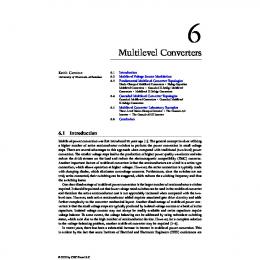
(4) With pulse-width modulation (PWM): great loss of power in the semiconductors and use of voluminous and expensive passive filters. (5) As2017, capacity Energies 10, 1709is concentrated, DC short-circuits are very difficult to limit. 2 of 26 To improve these aspects, multi-level VSC has been used [4]. However, it has severe limitations such As as capacity insufficient industrial scalability and limited number of voltage (5) is concentrated, DC short-circuits are very difficult to limit.levels [5]. The modular multilevel converter (MCC) (Figure 1), presented for the first time by Lesnicar and R. Marquardt [6], To improve these aspects, multi-level VSC has been used [4]. However, it has severe limitations improves these problems notably [7]: such as insufficient industrial scalability and limited number of voltage levels [5]. The modular (1) The arm current(MCC) flows continuously, avoiding VSC switching. multilevel converter (Figure 1), presented forthe thehigh firstdi/dt timeof bythe Lesnicar and R. Marquardt [6], (2) There is a great reduction of power losses and filtering needs. improves these problems notably [7]: (3) The capacity is distributed among the modules of each arm. (1) The arm current flows continuously, avoiding the high di/dt of the VSC switching. (4) The complexity does not increase substantially with the number of levels employed. (2) There is a currents great reduction of power losses and filtering (5) The fault in the DC side are smaller, makingneeds. them more suitable for multi-terminal (3) HVDC The capacity is distributed among the modules of each arm. grids. (4) The complexity does not increase substantially with the number of levels employed. Although publications on MMC have been made in very different orientations, this article is (5) The fault currents in the DC side are smaller, making them more suitable for multi-terminal oriented towards control and applications, so some important aspects such as reduction of HVDC grids. circulating currents [8–11] or modeling of the converter is not included [12–15].
Figure 1. Modular multilevel converter. Figure 1. Modular multilevel converter.
Since the MMC is a multi-level converter, the voltage harmonics generated are smaller than in a Although publications on MMC been in verycomponents different orientations, thiswhich articlecan is two-level converter, thus reducing thehave values ofmade the reactive of the filter, oriented towards control and applications, so some important aspects such as reduction of circulating even be eliminated in some cases. When a large number of modules is used, the switching frequency currents [8–11] or modelingand of the not included [12–15]. of the modules is reduced the converter converter is switching losses are minimized [16]. Since the MMC is a multi-level converter, the voltage harmonics generated are smaller than in a two-level converter, thus reducing the values of the reactive components of the filter, which can even be eliminated in some cases. When a large number of modules is used, the switching frequency of the modules is reduced and the converter switching losses are minimized [16].
Energies 2017, 10, 1709
3 of 26
Energies 2017, 10, 1709
3 of 25
When thedistance distance is long (greater than 400–700 50–60 km transmission at sea) DC When the is long (greater than 400–700 km on km land,on andland, 50–60and km at sea) DC transmission is cheaper than AC transmission. DC transmission cables, but is cheaper than AC transmission. DC transmission needs fewer needs cables,fewer but requires therequires presencethe of presence of electronic converters. Another limitation of AC transmission is the reactive energy that electronic converters. Another limitation of AC transmission is the reactive energy that consumes the consumes inductance of the line, distance which for long distance transmission becomes a fundamental inductancethe of the line, which for long transmission becomes a fundamental factor. MMC was factor. MMC was first usedCable in theproject Trans in Bay Cable project[16]. in San Francisco [16]. first commercially usedcommercially in the Trans Bay San Francisco The as follows. The article article has has been been organized organized as follows. Section Section 22 is is devoted devoted to to the the topologies topologies of of the the switching switching modules. Section 33 isisdedicated dedicatedtotothe thefundamental fundamentalequations equations relating voltages currents of modules. Section relating thethe voltages andand currents of the the DC side, AC side, switching modules, arm inductances, and circulating currents. Section 4 is DC side, AC side, switching modules, arm inductances, and circulating currents. Section 4 is devoted devoted to the balancing of the capacitors of the switching modules. Section 5 includes voltage and to the balancing of the capacitors of the switching modules. Section 5 includes voltage and current current modulators. 6 deals the connection of the converter to balanced, unbalanced or modulators. Section 6Section deals with thewith connection of the converter to balanced, unbalanced or distorted distorted grids. Section 7 includes high voltage (HV), medium voltage (MV), and low voltage (LV) grids. Section 7 includes high voltage (HV), medium voltage (MV), and low voltage (LV) applications. applications. Finally, Sectionto8 the is devoted to thein use of MMC in offshore Finally, Section 8 is devoted use of MMC offshore wind farms. wind farms. 2. Switching Module Topologies presented forfor MMC (by(by Lesnicar andand Marquardt [6]) The first first topology topologyof ofaaswitching switchingmodule module(SM) (SM) presented MMC Lesnicar Marquardt was the half bridge (HB)(HB) topology (Figure 2a), which has been most consists of two of IGBTs, [6]) was the half bridge topology (Figure 2a), which has the been the used. most It used. It consists two two diodes, and oneand capacitor. The SM is ONSM when T1 when is ON T1 andisT2 is and OFF T2 (Table 1), while OFF IGBTs, two diodes, one capacitor. The is ON ON is OFF (TableSM 1),iswhile when T1 iswhen OFF and is ON. the SM is ON, the isSM voltage is voltage the same SMas capacitor SM is OFF T1 isT2 OFF and When T2 is ON. When the SM ON, the SM is as thethe same the SM voltage, while when it is OFF zero. According to According the SM statetoand of the capacitor voltage, while whenthe it voltage is OFF isthe voltage is zero. thethe SMdirection state and SM current,ofthethe current the capacitor producing its charge/discharge, or it does not direction SM circulates current, through the current circulates through the capacitor producing its circulate through the its voltage. charge/discharge, or itcapacitor, does not maintaining circulate through the capacitor, maintaining its voltage.
Figure Figure 2. 2. Switching Switching module module (SM) (SM) topologies: topologies: (a) (a) half half bridge; bridge; (b) (b) full full bridge. bridge. Table currents of of the the switching switching module module (SM). (SM). Table 1. 1. State State of of conduction, conduction, voltages voltages and and currents State State SM State ONT1 State ON T2 State OFF ON OFFOFF ON ON ON ON OFFON OFF ON OFF OFF OFF ON OFF OFF ON OFF OFF ON
SM State
iSM0 > >0 < >0 < 0