Proceedings of the 2011 Winter Simulation Conference S. Jain, R.R. Creasey, J. Himmelspach, K.P. White, and M. Fu, eds.
DEFINING BACKGROUND TASKS IN SIMFC Jamal Siadat Janaka Y. Ruwanpura Reza Dehghan The University of Calgary 2500 University Dr. N.W. Calgary, AB, T2N 1N4, Canada ABSTRACT Process simulation in construction has proven to be a promising alternative for estimating project costs, driving initial schedules and estimating resource requirements. Different platforms have been developed which allow users to model various construction processes with different constraints. This paper introduces Simulator For Construction (SimFC) as a new construction-related simulator currently in development. Special emphasis is placed on defining and modeling background tasks within given processes. The validity and simplicity of SimFC is illustrated further in a case study where a pipe-rack construction process is modeled. The findings are of interest to construction planners, schedulers, estimators, project managers and researchers who are interested in using and promoting simulation in construction. 1
INTRODUCTION
Computer simulation allows for the modeling of various systems in a controllable and repeatable environment (Siadat et al., 2006). Simulation in construction management has been largely geared towards process modeling, which is to apply resources to tasks in a repetitive manner. Some have argued that process modeling can be used for estimating project costs, driving initial schedules and estimating resource requirements (e.g., Sawhney and AbouRizk 1995; Halpin and Martinez 1999). One of the most important factors in planning construction projects is having a complete and accurate understanding of the project scope and required resources. However, due to the unpredictable nature of the construction industry, the availability of resources cannot be accurately predicted in the estimating phase. For example a number of trucks can be (and typically are) shared amongst several projects. Depending on the importance of a project and the timelines associated with it, the management team may assign more trucks to a particular project. As a result, the resource allocation activity is often performed at construction time. A model that would allow construction planners to experiment with various activity sequences, allocation of man-power, equipment needs and material availability would be of great benefit for the construction industry. For this aim different platforms have been developed where each allow their respective users to model various scenarios using pre-defined modeling elements. These include (but are not limited to) entities, activities and various resources. Furthermore, these platforms allow users to experiment with different paths that an entity might take given a defined set of constraints. However, major difficulties arise when attempting to model processes which cannot be accurately represented using the provided elements within a given platform. An analysis of today’s construction simulators by the authors has resulted in an identification of areas for potential improvement in process modeling. While discussing the specifics of these is beyond the scope of this paper, some of the (likely) enhancements can be summarized as: Integration of scheduling and process simulation 978-1-4577-2109-0/11/$26.00 ©2011 IEEE
3406
Siadat, Ruwanpura and Dehghan Ease of template definition User experience improvements Sharing entities and resources between different processes Improved tracing support Background task support Simulator For Construction (SimFC) is a process-driven construction simulator currently in development at the University of Calgary. The overall goal is to develop a simulation platform which would improve the user simulation experience by incorporating the above mentioned enhancements. This paper is focused on the last item by defining background tasks and discussing their necessity for process modeling. The remainder of the paper is structured as follows. Section 2 reviews the various simulators used to model construction processes. Background tasks and their necessity are defined in section 3. Section 4 presents the various SIMFC modeling elements. Section 5 discusses a SimFC application based on a steel pipe-rack construction model. This model serves as case study illustrating the effectiveness and simplicity of SimFC in the modeling and simulation of complex construction processes. The results of this case study are outlined in section 6. Finally, the concluding remarks are added in section 7. 2
RELATED WORK
The benefits of computing power with respect to simulating construction projects have long been realized. Haplin illustrates the need for project managers to consider activities on the job site that are repetitious in nature and defined them as processes (Halpin 1977). The CYCLONE method is proposed to better study and analyze these processes. A graphical representation is used to demonstrate activities with and without resources along with various statistic collection elements. The model is then translated to a program which upon running provides the user with the statistics collected. CYCLONE was used to model the process of concrete placement in the Peachtree Center Plaza Hotel in Atlanta, GA. Martinez presented Stroboscope which is an acronym for STate and ResOurce Based Simulation of Construction ProcEsses. (Martinez and Ioannou 1994). To demonstrate the effectiveness of this platform, an example of an airplane service center is discussed. Since the overall maintenance time depends on several factors (e.g., number of engines, availability of inspectors, level of maintenance, etc), the airplane down-time costs due to delays in the maintenance queues are computed. While both CYCLONE and Stroboscope are powerful simulation frameworks, they require users to have an in depth programming knowledge of the platforms. This is a challenging task for end-users as they are construction planners and schedulers and not computer programmers. AbouRizk and Hajjar argued that special purpose simulators are easier to use yet provide the level of depth required to accurately model complex construction processes (AbouRizk and Hajjar 1998). Based on this argument three separate special purpose simulators were developed: Earth-Moving: The earth-moving model was used to demonstrate how this platform can be used to simulate various uncertainties involved in soil relocation (more commonly known as earthmoving operations). CRUISER: This model was developed to provide end-users with a tool to analyze plant design alternatives. CSD: CSD allowed for the optimization of construction site dewatering operations. A major difficulty in the above approach arises as each process should be developed and modeled by experts. This can be a cumbersome and time-consuming investment. Recognizing this difficulty, the authors shifted their efforts to the development of a new general purpose simulator based on software engineering principals (Hajjar and AbouRizk 2000; Hajjar and AbouRizk 2002). They presented a new special purpose simulator for construction purposes called SIMPHONY. The earth-moving and CRUISER examples were re-implemented. It was demonstrated that the man-hours required to program the earth-moving process was reduced to 28 hours (from the original 400 hours). Furthermore, the total man-hours required to model the CRUISER was only 40 hours (compared to the original 650 hours).
3407
Siadat, Ruwanpura and Dehghan Recognizing some of the modeling complexities of SIMPHONY and its predecessors, Lu designed a new framework for modeling construction activities called SDESA (Lu 2003). Several fundamental design changes were made in order to make the simulator more intuitive and enhance its usability. This model was used to simulate a granular basecourse construction where truckloads of granular material are dumped to the site and then graded, moistened and compacted. It was also used to simulate the duration a road pavement construction activity, where trucks brought in the asphalts and dumped, compacted and paved on site. SIMPHONY and SDESA can be thought of as more recent simulation platforms which have offered users the ability to model complex scenarios by simply interacting with various predefined components. However, none of them address the technically simpler but conceptually more problematic issue of background tasks which is presented here. 3
DEFINING BACKGROUND TASKS
Tasks represent specific construction activities. Generally, each task introduces a set of delays to an entity and uses a set of resources. Task examples include brick-laying using a labour as a resource or traveling which may use a vehicle as a resource. Typically, tasks must have an entity as an input, perform a set of operations using the assigned resources and finally, release the entity to the next task. Traditionally, construction process modeling has allowed for connecting a series of tasks in a cyclical manner. A common example used to illustrate construction processes is the earth-moving cycle. The objective of this process is to move soil from one location to another using trucks. For each of the defined tasks, the user can specify a specific set of resources and a duration. This allows users to create more realistic models as for example the return trip of a truck in an earth-moving cycle is generally faster as there is less weight on the truck. Figure 1 illustrates the earth-moving process using trucks as entities. This is a reasonable modeling construct as long as the amount of soil transported is equal to the truck capacity. However, this model contains a rather interesting behaviour which has been overlooked. Trucks are being “loaded” and “unloaded”. Given that models are abstract representations of real world systems (Sánchez 2007), it is difficult to correlate between the real world process and the abstract model. Further complexities arise when considering further operations after the unloading. For example if the soil needs to be compacted or piled up, it would be difficult to represent this behaviour as the entity in use is a truck and trucks cannot be compacted or piled up. A different model can be proposed similar to Figure 2 which addresses the above mentioned shortcoming. In this model, soil is the entity and trucks are the resources. Soil is loaded onto the trucks, transported and unloaded. However, as motioned, tasks must have an entity to perform an operation. If all entities are unloaded, there are no entities to enter the final task (traveling back). To model this process in existing platforms, a model similar to Figure 3 can also be presented. Soil is used as an entity, transported and unloaded. At that time a secondary or “filler” entity is introduced to simply move the truck back to the loading area. Needless to say, the “filler” entity should be destroyed as soon as the truck returns. The drawback of this approach lies in the introduction of the additional entity, which yet again is an inaccurate depiction of real world behaviour. Finally, a model similar to Figure 4 can be used. This model eliminates the cycle and creates a linear network where a new entity can enter the system upon the completion of the final activity. Similar to the previous model, there are no entities to enter the final task. Furthermore, this type of network does not take full advantage of the process modeling capabilities, which is the ability to define cyclical processes. It’s important to note that all of the above mentioned models will produce similar (and valid) statistical results and therefore, most modellers tend to overlook the fact they may not depict real world behaviour. For example (Dehghan et al., 2009) attempted to model a pipe-rack construction process (Figure 5). As part of this process, steel was transported from a steel yard to a construction site using trucks. Steel was chosen as the entity and trucks were defined as resources. However, in order to address the modeling dilemma discussed earlier, the task “travel to the yard” was placed on the critical path with no return to 3408
Siadat, Ruwanpura and Dehghan the loading area. In their defense, connecting this task would have meant that the same steel would proceed further to inspection and installation and return back to the loading area. Furthermore, regardless of the approach the statistics produced by their model seems to be valid and little difference would be observed in the overall outcome. Loading
Truck(s)
Traveling to Dump Site
Unloading
Traveling Back
End
Figure 1: A flowchart of the earth-moving cycle using trucks as entities
Truck(s)
Loading
Soil
Traveling to Dump Site
Traveling Back
Unloading
End
Figure 2: A flowchart of the earth-moving cycle using soil as entity
Truck(s)
Traveling to Dump Site
Loading
Soil
End
Traveling Back
Unloading
“Filler”
Figure 3: A flowchart of the earth-moving cycle using soil and a secondary entity
3409
Siadat, Ruwanpura and Dehghan
Truck(s)
Soil
Loading
Traveling to Dump Site
Unloading
Traveling Back
End
Figure 4: A flowchart of the earth-moving without a cycle
Figure 5: Steel pipe-rack construction model in SIMPHONY (from (Dehghan et al., 2009)) In order to address the mentioned issues, a re-examination of the earth-moving process is necessary. If soil is considered to be the entity, initially it is loaded, then transported and finally unloaded. Upon returning, the truck will not carry any soil. Two key observations can be made as follows: 1. The process is definitely of cyclical nature; and 2. In the final task the truck is not transporting material and therefore, there should be no entities associated with it
3410
Siadat, Ruwanpura and Dehghan This has lead the authors to define background tasks. These are tasks that do not require an entity to be executed and their sole purpose is to utilize a particular set of resources for a period of time. SimFC is a simulation platform currently in development which lets users specify background tasks where appropriate. The overall aim of this approach is to allow users to model real world processes more accurately. Another important property of SimFC lies in its ability to distinguish between entity time and project duration. Entity time is defined as the total time that an entity has remained in the system. Duration on the other hand does not account for background tasks. In the earth moving example, the duration is comprised of the entire cycle while the entity time only considers the first three tasks. The difference between the two is the amount of time that was spent waiting on resources to be released from the background tasks. The subsequent section highlights the various SimFC elements and discusses how this system models the execution of background tasks internally. 4
SIMFC MODELING ELEMENTS
Similar to many of its predecessors, SimFC is an event-based Monte-Carlo simulator. Random numbers are used to specify various system inputs. After a set of computations has been performed the outputs are calculated and presented as data ranges which are graphically illustrated as well. SimFC is comprised of five major modeling elements. Below is a more detailed examination of each. 4.1
Entities
Entities are what drive the system and flow through activities. The user can specify several properties for the entities which include the initial time the entity enters the system, intervals between each of the entities entering the system, the total number of entities and specific attributes which can be assigned to an entity. All the values can be fixed or stochastic. For example, in a traffic simulation study where vehicles are the entities, a user can specify 1000 vehicles to be traversing through a set of roads with the first vehicle arriving at time 0 and a normal distribution of (1, 2) as the interval for each subsequent entity to enter the system. Attributes such as vehicle size and speed can also be assigned to the entities. 4.2
Tasks
A task is the fundamental unit of any construction project. A task is a simple straight-forward activity with a clear objective. Connecting the tasks yields a network which entities must traverse. Every task has a duration and a set of required resources associated with it. A task with no resources attached to it only adds delays to the overall process. Tasks can also combine entities or separate them. If concrete mixing is considered as a task for example, water, aggregates and cement should be mixed to create the concrete. In a finish-to-start network (which is discussed here), the total duration for a project is the total time an entity must spend to reach the last task from the first. Background tasks can be also specified where by the task will require no entity to execute. Internally, a background task is scheduled for execution via a notification from the previous task. If all resources are available the task will be executed, otherwise, the task will await until all resources are available. 4.3
Resources
Resources are required to accomplish tasks. In other words if the resources for a particular task are available, the task can be executed, otherwise the entity must wait until the resource is available. A user can specify a wide range of resources including labor, material and equipment. The main resource attribute is the cost associated with using them.
3411
Siadat, Ruwanpura and Dehghan 4.4
Composites
A composite element is an element which can contain any other element. Generally a composite element contains a number of tasks or other composites. It is used to distinguish different subsets of the project (also known as work break-down structures). 4.5
Interrupts
Interruptions can occur to entities, resources or tasks. They can be used to model certain unforeseen events. The user can specify the effect of each interrupt on specific tasks, entities or resources and the probability of its occurrence. Other components such as probabilistic and deterministic branching are also included in SimFC, however, they are not included as separate components. For example probabilistic branching only occurs after task executions; therefore, it has been included as an option under the task component. SimFC is also being developed to improve the user experience by eliminating the user’s need to learn specific programming languages. Furthermore, it attempts to bridge the gap between CPM based scheduling and process modeling. However, the specific details of these implementations are beyond the scope of this paper. The following section presents a case study outlining the need for background tasks in order to define more accurate models. 5
CASE STUDY: STEEL PIPE-RACK CONSTRUCTION
This section presents a brief background on pipe-racks and describes the pipe-rack model as originally implemented by (Dehghan et al., 2009). Pipe-racks are one of the most important structures used in oil and gas facilities. They are large support structures that hold pipes, cables and equipment of various shapes and sizes. Typically, process engineers calculate the type, size and the flow capacity of the pipes required for the facility. Mechanical and instrumentation engineers must also specify the type of equipment that will be installed on the pipe-rack. Structural engineers use this information and while considering the availability of construction material, design the pipe-rack. In terms on construction, however, pipe-racks are the one of the very first structures that should be built. As a result, it is crucial for construction companies to plan for material, equipment and personnel availability during the construction phase as slippages may delay the entire project. Typically, pipe-racks are constructed from steel as they are both durable and have a high strength resulting in a high holding capacity. However, in certain areas where using steel is not economically feasible or weather conditions tend to corrode the steel at a rapid rate, concrete is used as an alternative. For the purpose of this study only the steel pipe-rack construction operations are considered. As previously mentioned, the benefits of simulation, with respect to modeling construction processes, has long been realized. A model that can accurately predict the duration, cost and resource requirements for pipe-rack projects can greatly benefit organizations involved in oil and gas construction. 5.1
Model Details
Pipe-racks are comprised of a set of frames or portals. Each portal is generally constructed of two vertical columns which are connected via a set of horizontal beams. Portals are also connected to each other via a set of longitude beams. Depending on the facility requirements, a Pipe-rack can have many levels. This study models the construction of a 5-level pipe-rack. This model was presented earlier in Figure 5. Initially, trucks are used to move steel from the steel yard to the construction site. The fundamental difference between the SimFC and SIMPHONY models is that the traveling to yard task is modeled as a background task and is connected to the loading task. It is assumed that initially trucks are loaded with two columns, then two beams and finally two bracings. Upon the truck’s arrival at site, the steel will be unloaded and the truck will head back to the yard. The steel is
3412
Siadat, Ruwanpura and Dehghan then inspected to ensure that it has been properly coated against corrosion and fire. If that is not the case, the worker will recoat them. A crane is then used to install the columns, then beams and finally place the bracings in the appropriate position one level at a time. In the context of this study 8 longitudinal and 2 traversal columns as well as a single siding for each longitudinal frame is considered. Table 1 illustrates the entities that are used in this model along with their various properties while similarly; Table 2 presents the tasks and their properties. It is assumed that only a single resource of each type (i.e., a single truck, crane, inspector and worker) is available to perform the tasks mentioned above. The model is a simplified abstract of real world pipe-rack construction. Similar to what (Dehghan et al., 2009) have mentioned, the following assumptions have been made: The required nuts and bolts are always available The levels were all to be built in a similar fashion Only a single crane can be used to lift the steel components Safety factors, weather conditions and other site interruptions were not modeled The model only comprises of the construction component of a steel pipe-rack The portals were not pre-fabricated and there are no re-works after installation The delay caused by workers working on connecting the various components is negligible Table 1: Model tasks and their properties Entities
Quantities
Weight (Tons)
Column
16
20
Beam
110
10
Bracing
56
5
Table 2: Model entities and their properties Resources Used
Durations (Min)
Loading
Truck
Triangular (3,5,7)
Travel to and from site
Truck
Uniform (4,6)
Unloading
Truck
Tasks
Installation
Inspection Repair and Modification
6
Crane
Triangular (2,4,5) Columns: (17,20,35) Beams: (10,15,25) Bracings: (10,15,25)
Triangular. Triangular Triangular
Inspector
Uniform (2,5)
Worker
Normal (90, 120,150)
RESULTS
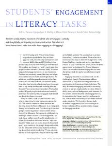
In order to validate the results obtained by SimFC, they are compared to the findings of (Dehghan et al., 2009). Figure 6 shows a side by side comparison of the durations that were obtained in both platforms. While in SIMPHONY, the total duration for this operation is estimated to be between 3060 and 3260 minutes, the results obtained from SimFC are between 3052 and 3253 minutes. The results do slightly vary, however, they are comparable overall. As previously mentioned, SimFC also computes the overall process entity time which is illustrated in Figure 7. The slight variation between the entity time and duration is because of the background task. In this particular scenario, since the duration of the background task is relatively negligible compared to the overall process duration, the difference between the process duration and entity time is minimal. However, this model still illustrates that in certain situations, the entity time would be more reflective of the actual process duration as the traveling to yard task should not be considered part of the overall process duration (in other words this task should not be part of the critical path).
3413
Siadat, Ruwanpura and Dehghan 100%
100
90%
90
80%
80
70%
70
60%
60
50%
50
40%
40
30%
30
20%
20
10%
10
0% 3060
3110
3160
3210
0 3050
3260
3100
(a)
3150
3200
3250
(b)
Figure 6: Probability of resulted duration of pipe-rack installation over 100 runs. The figure on the left (a) is obtained from SIMPHONY while the graph on the right (b) is obtained from SimFC. The X-axis represents the total duration (in minutes) while the Y-axis is the probability of occurrence. 100 90 80 70 60 50 40 30 20 10 0 3000
3050
3100
3150
3200
3250
Figure 7: Probability of resulted entity time of pipe-rack installation over 100 runs. SimFC has also calculated the mean resource utilization rate of the truck to be 24.12% and the crane utilization rate was 99.74%. These numbers are comparable to the findings of (Dehghan et al., 2009) (truck utilization rate of 23.45% and crane utilization rate of 99.62%). The results shown here demonstrate that SimFC has indeed produced valid statistics, however, more importantly, by defining a background task, the user is modeling the real world processes more accurately. Furthermore, the statistics collected by the entity time allows the user to compare the results between the project duration and the actual time which entities spent in the system. By comparing the two, the user can determine which is better suited to represent the overall duration. 7
CONCLUSION
Process-based simulation is extensively used to model various construction scenarios. These type of simulators have the ability to model cyclical sequence of events and allow for the introduction of various uncertainties. This allows the end user to experiment with various what-if scenarios in order to better estimate project costs, schedule and resource requirements.
3414
Siadat, Ruwanpura and Dehghan Several earth-moving models were presented in this paper. While they all produce valid statistical outputs, it is difficult to see how they would accurately model the real life earth-moving process. In order to overcome this obstacle, a simulator for construction or SimFC has been introduced. While there are several key objectives for this platform, the work presented here is focused on the introduction of background tasks and how they can be used to accurately model cyclical processes. A case study involving a steel pipe-rack construction showed that while SimFC has the abilities found in other simulation platforms, it is also a promising tool which could potentially enhance simulation by mapping real world construction processes to a simulation model more accurately and allowing for a separation between entity time and project duration. The limitations of the case study, lies in the assumptions which were made. A complete steel piperack construction model should include all construction-related aspects. This includes all the properties of the steel being used (including size, cost, etc) as well as a detailed account for all resources and an accurate break-down of all tasks. Furthermore, this study assumes a uniform five level structure which is rarely found in real construction sites. A flexible model allowing for the simulation of steel pipe-rack structures with different specifications would be more beneficial to the industry. Overall, the main limitation of this work is that SimFC is still in the development phase. This platform should be completely developed and extensively tested before a judgement can be made on its effectiveness with addressing the goals set in this paper. More studies and industry support is required to help improve the usability and accuracy of this platform. REFERENCES AbouRizk, S., and D. Hajjar. 1998. “A Framework for Applying Simulation in the Construction Industry.” Canadian Journal of Civil Engineering, 25, No. 3:604-617. Dehghan, R., F. Khoramshahi, and J. Ruwanpura. 2009. “Developing a general purpose simulation model for steel pipe-rack installation.” In Proceedings of the 2009 Spring Simulation Multiconference (SpringSim '09). Society for Computer Simulation International, San Diego, CA, USA, Article 172, 8 pages. Hajjar, D., and S. AbouRizk. 2000. “Application Framework for Development of Simulation Tools.” Journal of Computing in Civil Engineering, 14, No. 3:160-167. Hajjar, D., and S. AbouRizk. 2002. “Unified Modeling Methodology for Construction Simulation.” Journal of Construction Engineering and Management, 128, No. 2:174-185. Halpin, D.W. 1977. “CYCLONE: method for modeling of job site processes.” American Society of Civil Engineering Journal of the Construction Division, 103, No. 3:489–499. Halpin, D. W., and, L. Martinez. 1999. “Real world applications of construction process simulation”. In Proceedings of the 1999 Winter Simulation Conference, edited by P.A. Farrington, H.B. Nembhard, D.T. Sturrock, and G.W. Evans. Piscataway, New Jersey: Institute of Electrical and Electronics Engineers, Inc.. Lu, M. 2003. “Simplified Discrete-Event Simulation Approach for Construction Simulation.” Journal of Construction Engineering and Management, 129, No. 5:537-546. Lu, M., and W. Chan. 2004. “Modeling concurrent operational interruptions in construction activities with Simplified Discrete Event Simulation Approach (SDESA).” In Proceedings of the 2004 Winter Simulation Conference, edited by R. G. Ingalls, M. D. Rossetti, J. S. Smith, and B. A. Peters, 12601267. Piscataway, New Jersey: Institute of Electrical and Electronics Engineers, Inc. Martinez, J. C., and P. G. Ioannou. 1994. “General purpose simulation with stroboscope.” In Proceedings of the 1994 Winter Simulation Conference, edited by J.D. Tew, S. Manivannan, D. A. Sadowski, and A. F. Seila, 1159-1166. Piscataway, New Jersey: Institute of Electrical and Electronics Engineers. Sánchez, P. J. 2007. “Fundamentals of simulation modeling”. In Proceedings of the 2007 Winter Simulation Conference, edited by S. G. Henderson, B. Biller, M.-H Hsieh, J. Shortle, J. D. Tew, and R. R. Barton, 54-62. Piscataway, New Jersey: Institute of Electrical and Electronics Engineers, Inc.
3415
Siadat, Ruwanpura and Dehghan Sawhney, A., and S. AbouRizk. 1995. “HSM-Simulation–Based Planning Method for Construction Projects.” Journal of Construction Engineering and Management, 121, No. 3:297-303. Siadat, J., R. J. Walker, and C. Kiddle. 2006. “Optimization aspects in network simulation.” In Proceedings of the 5th international Conference on Aspect-Oriented Software Development (Bonn, Germany, March 20 - 24, 2006). AUTHOR BIOGRAPHIES JAMAL SIADAT is a PHD candidate in the Department of Civil Engineering, Project Management Specialization at the University of Calgary. With a background in software engineering and simulation, Jamal’s main research objectives are to improve the overall simulation experience for all users. His e-mail is
[email protected]. JANAKA Y. RUWANPURA is a Professor in the Department of Civil Engineering and the Director for the Centre for Project Management Excellence at the University of Calgary. He is also the Canada Research Chair in Project Management Systems. He has a diverse research portfolio including simulation, risk management and productivity studies. His collaboration with the industry has resulted in the identification of the top ten factors for improving construction productivity. This ground breaking work is an ongoing area of research with many potential benefits to the industry as a whole. Dr. Ruwanpura’s e-mail is
[email protected]. REZA DEHGHAN is a PHD candidate in the Department of Civil Engineering, Project Management Specialization at the University of Calgary. His main research areas are schedule compression, project fast-tracking, and construction simulation. His e-mail is
[email protected].
3416