Demonstrational and Constraint-Based Techniques for Pictorially Specifying Application Objects and Behaviors Brad Vander Zanden
Brad A. Myers
Computer Science Department University of Tennessee Knoxville, TN 37996
[email protected]
School of Computer Science Carnegie Mellon University Pittsburgh, PA 15213
Abstract The Lapidary interface design tool is a demonstrational system that allows the graphics and run-time behaviors that go inside an application window to be specified pictorially. In particular, Lapidary allows the designer to draw example pictures of application-specific graphical objects that the end user will manipulate (such as boxes and arrows, or elements of a list), the feedback that shows which objects are selected (such as small boxes on the sides and corners of an object), and the dynamic feedback objects (such as hair-line boxes to show where an object is being dragged). The run-time behavior of all these objects can be specified in a straightforward way using constraints, demonstration, and dialog boxes that allow the designer to provide abstract descriptions of the interactive response to the input devices. Lapidary generalizes from these specific example pictures and behaviors to create prototype objects and behaviors from which instances can be made at run-time. A novel feature of Lapidary’s implementation is its use of constraints that have been explicitly specified by the designer to help it generalize example objects and behaviors, and to guide it in making inferences. CR Categories and Subject Descriptors: D.2.2 [Software Engineering]: Tools and Techniques—User Interfaces; I.3.6 [Computer Graphics]: Methodology and Techniques. General Terms: Human Factors. Additional Key Words and Phrases: User Interface Management Systems, Interaction, ObjectOriented Design, Direct Manipulation, Interaction Techniques, Programming by Example.
Lapidary
-1-
1 Introduction Numerous toolkits have been developed to allow designers to pictorially develop interfaces that consist primarily of predefined widgets (e.g., menus, buttons, and sliders) and static bitmap backgrounds. They typically provide developers with a palette of predefined widgets, such as menus, buttons, and scrollbars, and allow copies of these items to be arranged in various graphical layouts. Some tools, such as the NeXT Interface Builder [35], allow a designer to pictorially specify that a widget will control the property of a dynamic, graphical object. However, these tools provide no support for pictorially specifying graphical objects that are composed from graphical primitives, such as circles, lines, and rectangles, and whose properties change in response to direct manipulation by a mouse, rather than by manipulation of pre-defined widgets. Thus, for example, they do not provide a drawing editor that would allow a designer to create arbitrary graphics. Nor do they provide mechanisms such as constraints or TeX-like glue [15] for specifying arbitrary layout arrangements for the graphics. Finally, they do not provide pre-defined behaviors, such as a move behavior or a selection behavior, that can be used with arbitrary graphics (e.g., these tools might associate a selection behavior with a collection of buttons, but the behavior is tightly coupled to these buttons and cannot be modified to allow selection of a node in the boxes-and-arrows editor shown in Figure 1, or even to allow selection of an object from the editor’s object pallette). To create these objects and behaviors, a designer typically must use the base language of the intended application, such as C. It has been estimated that the amount of time required to develop these application-specific graphics and behaviors is about two orders of magnitude greater than the time required to create the widgets that surround an application window [37]. Consequently, it would be desirable to have a tool that allowed these aspects of an application to be specified pictorially. Lapidary is such a tool. It is an interactive, programming-by-example, design tool that allows designers to pictorially create highly interactive, graphical interfaces. Lapidary is primarily intended for the creation of interfaces whose content is high in graphics composed from primitive graphical objects such as circles, rectanges, lines, and simple text strings, and whose properties change in response to mouse- and keyboard-based input. Lapidary can specify high-level behaviors on these objects, such as move/resize, selection, object creation, and text editing of simple strings and can also specify the ‘‘syntactic’’ feedback associated with these behaviors, such as dashed-line feedback boxes or selection handles. Finally, Lapidary can be used to define behaviors for dynamic bitmaps (e.g., moving a bitmap, creating a copy of a bitmap, selecting a bitmap), although it does not provide facilities for drawing bitmaps. Lapidary is not designed for the creation of sophisticated text editors, or for the creation of interfaces that consist exclusively of static bitmap backgrounds and predefined widgets (e.g., menus, sliders, and buttons). It is also not designed to specify the ‘‘semantic’’ feedback of behaviors that is typically encapsulated in callback procedures, such as the code that deletes an object or the code that creates a copy of an object (strictly speaking, such code is part of the underlying application, not the user interface). Figures 1 and 2 illustrate the types of interfaces Lapidary is intended to create. To create the boxes and arrows editor shown in Figure 1, a designer has used Lapidary to 1) create and lay out the
Lapidary
-2-
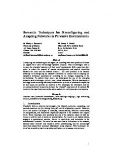
Figure 1: A boxes and arrows editor. Existing graphical toolkits can be used to create the delete-quit menu but cannot be used to create 1) the application graphics, such as the labeled box, arrow, and object pallette, 2) the layout of the application graphics, such as keeping the arrows’ endpoints attached to the centers of the boxes, or making the boxes expand to accommodate a particularly long text string, and 3) the application graphics behavior, such as selecting a box or arrow, moving a box, or creating a new box or arrow. In contrast, Lapidary allows all these graphics, and all but the ‘‘semantic’’ aspect of the behaviors (e.g., creating an instance of an arrow or box once its image has been swept out with the mouse) to be created in a direct manipulation manner. object palette; 2) create the application’s graphical objects, such as the labeled boxes and arrows; 3) define the layout of the output, such as keeping the endpoints of the arrows centered within the boxes they connect; and 4) define the ways in which the user can interact with the output, such as moving or resizing the labeled boxes, or changing the labels. As another example, in Figure 2, a designer has used Lapidary to create the gameboard, game pieces, and peg generator, as well as the behaviors that allow the user to drag pieces around the gameboard, and from the ‘‘peg generator’’ to the gameboard. A designer creates an interface using Lapidary by drawing examples of application objects and attaching behaviors to them. Lapidary then generalizes these examples into prototype objects that can be instanced at run-time by an application. Lapidary provides a number of features that assist the designer in creating these examples, including: 1) a drawing editor that allows a designer to draw concrete examples of application objects; 2) a set of iconic constraint menus and access to a spreadsheet program that allows a designer to attach constraints to objects that specify how the objects relate to one another (e.g., that arrows stay attached to boxes); and 3) a set of demonstrational techniques and dialog boxes that provide access to a set of abstract interactors that embody particular kinds of interactive behaviors.
Lapidary
-3-
Drawing Window 3
⊷⊷⊷⊷⊷⊷⊷⊷⊷⊷⊷⊷⊷⊷⊷⊷⊷⊷ ⊷⊷⊷⊷⊷⊷⊷⊷⊷⊷⊷⊷⊷⊷⊷⊷⊷⊷ ⊷⊷⊷⊷⊷⊷⊷⊷⊷⊷⊷⊷⊷⊷⊷⊷⊷⊷ New Game ⊷⊷⊷⊷⊷⊷⊷⊷⊷⊷⊷⊷⊷⊷⊷⊷⊷⊷ ⊷⊷⊷⊷⊷⊷⊷⊷⊷⊷⊷⊷⊷⊷⊷⊷⊷⊷ ⊷⊷⊷⊷⊷⊷⊷⊷⊷⊷⊷⊷⊷⊷⊷⊷⊷⊷
⊷⊷⊷⊷⊷⊷⊷⊷⊷⊷⊷⊷⊷⊷⊷⊷⊷⊷ ⊷⊷⊷⊷⊷⊷⊷⊷⊷⊷⊷⊷⊷⊷⊷⊷⊷⊷ ⊷⊷⊷⊷⊷⊷⊷⊷⊷⊷⊷⊷⊷⊷⊷⊷⊷⊷ ⊷⊷⊷⊷⊷⊷⊷⊷⊷⊷⊷⊷⊷⊷⊷⊷⊷⊷ Quit ⊷⊷⊷⊷⊷⊷⊷⊷⊷⊷⊷⊷⊷⊷⊷⊷⊷⊷ ⊷⊷⊷⊷⊷⊷⊷⊷⊷⊷⊷⊷⊷⊷⊷⊷⊷⊷ ⊷⊷⊷⊷⊷⊷⊷⊷⊷⊷⊷⊷⊷⊷⊷⊷⊷⊷
Peg Generator
Figure 2: A solitaire type of checkers game, in which the player ‘‘takes’’ pegs by jumping over them into an unoccupied hole. The goal is to leave only one peg on the board. Existing graphical toolkits can be used to create the new-game/quit menu but cannot be used to create 1) the application graphics, such as the game pieces, the peg generator, and the gameboard, 2) the layout of the application graphics, such as the alignment of the holes or the alignment of the ends of the pegs with the centers of the holes, and 3) the application graphics behavior, such as jumping a peg by moving a peg to an unoccupied hole, or creating a new peg by dragging one from the peg generator to an unoccupied hole. In contrast, Lapidary allows all these graphics and all but the ‘‘semantic’’ aspects of the behaviors (e.g., the deletion of a jumped peg or the creation of an instance of a peg when the dragging operation from the peg generator terminates) to be created in a direct manipulation manner.
Lapidary
-4-
A novel aspect of Lapidary is its use of constraints to aid it in generalizing concrete examples into prototype objects and in infering the parameters for these prototype objects. For example, Lapidary constructs constraints that pass parameter information from a parent object to its children, infers which objects referenced by a constraint are parameters based on whether the objects belong to a composite object or are outside of it, and uses constraints to lay out the parts of an object. Lapidary also uses constraints to support the demonstration of certain types of behaviors through ‘‘before’’ and ‘‘after’’ inferencing. The designer uses constraints to define the ‘‘before’’ and ‘‘after’’ behaviors. Lapidary determines the differences between the constraints, and creates code to activate the appropriate constraints based on the state of the interface. Lapidary is part of the Garnet user interface development environment [26] and is one of the interactive tools that provide a visual programming environment for Garnet. A preliminary version of Lapidary was presented in [23]. This paper describes the completed version of the system which makes a number of major additional contributions. First, the current version of Lapidary significantly expands the use of constraints as a technique for supporting inferencing and the generalization of example objects. In addition to graphical layout, constraints are now used to create and infer parameters of objects (i.e., the properties of an object that differ among each of its instances), to control interactive responses to input based on the properties of selected objects, and to specify the ‘‘before’’ and ‘‘after’’ states in demonstrational programming. Lapidary previously tried to perform many of these tasks without the assistance of constraints, and often guessed incorrectly. Second, Lapidary now uses a rigorous technique based on pointer variables that employs constraints to support inferencing and to generalize constraints. When the preliminary version of Lapidary was presented, Garnet did not yet have a formal mechanism for defining composite objects (objects composed from other objects). Consequently, Lapidary used ad hoc techniques for generalizing objects and behaviors (constraints were not even used for inferencing, due to the lack of this formal mechanism). Finally, we now have five years of experience with Lapidary and this paper provides a comprehensive report of what we have learned. It includes empirical results about the usability of Lapidary, its efficiency in creating user interfaces, and implementation issues that developers of future visual tools might wish to consider. The rest of this paper is organized as follows. Section 2 discusses related work. Section 3 presents an overview of Lapidary capabilities. Section 4 discusses how designers create example objects in Lapidary and Section 5 describes how these objects are generalized into prototype objects. Similarly, Section 6 discusses how designers create example behaviors in Lapidary and Section 7 describes how these behaviors are generalized into prototype behaviors. Section 8 provides a complete example of how a designer would create an interface in Lapidary and Section 9 discusses empirical results about the usability of Lapidary and implementation experience. Finally Sections 10 and 11 present directions for future research and conclusions. A ‘‘Lapidary’’ is a workman who cuts, polishes and engraves precious stones, and here is a Lisp-Based Assistant for Prototyping Interface Designs Allowing Remarkable Yield. Lapidary has been released and can be acquired by anonymous FTP as part of Garnet. For information on how to do this, contact
[email protected]. A complete reference manual for Lapidary is also available [30].
Lapidary
-5-
2 Related Work Lapidary can be classified under the broad heading of User Interface Management Systems [24]. It provides capabilities that are found in interface builders, widget builders, application builders, behavior builders, and constraint builders. However, each of these types of tools allows only a limited set of graphics or behaviors to be specified. Lapidary goes beyond these tools in that it allows arbitrary application graphics and their behaviors to be pictorially specified. Thus, whereas previous tools have focused on specifying one aspect of the user interface, Lapidary provides a comprehensive set of tools that allows all aspects of a user interface to be specified pictorially.
2.1 Interface Builders There have been a large number of systems that allow users to select items from a pre-defined library of widgets, and position them on the screen. Some of these, including Menulay [2], Trillium [7], DialogEditor [3], vu [40], Druid [41], Gilt [28], and the NeXT Interface Builder [35], provide a graphical editor that allows the position and size of each widget to be specified in a direct manipulation manner using a mouse. Often, these systems allow a few limited properties to be changed using a dialog box. Lapidary also provides the ability to create and align pre-defined widgets using its drawing and constraint editors.
2.2 Widget Builders The Peridot system [21, 22] supports creating the widgets themselves using direct manipulation. It provides a drawing editor that allows a user to create widgets with many different types of looks-andfeels. It also provides an inferencing facility that helps align objects and attempts to guess the behaviors the widgets should exhibit. Lapidary also allows widgets to be created from scratch with many different types of looks-and-feels. However, Peridot contains a great deal of knowledge about various interaction techniques, such as menus and sliders, and thus is able to perform much more sophisticated inferencing of widget behaviors. Lapidary is more general than Peridot since it can also handle application-specific graphics, so it does not have the knowledge that would allow this style of inferencing. Instead it allows behaviors to be created through dialog boxes and a limited form of ‘‘before’’ and ‘‘after’’ demonstration (see Section 6.3).
2.3 Application Builders Most interface builders primarily support the construction of relatively static panels or dialog boxes where the objects in the panels are menus, buttons or text fill-in slots that do not move around. A number of systems support the creation of more dynamic presentations. For example, XY-Wins [6] allows users to draw mobile objects, such as elements of visual programming languages. However, these systems still allow only limited properties to change at run time (such as position). Other systems, such as EDGE [34] support more dynamic behavior by limiting the applications to a certain form, such as those that use graphs to display their data. Lapidary improves on the capabilities of these application builders by allowing all aspects of the dynamic presentation of an application to be pictorially specified, including the properties that should change at run-time and the behaviors that objects should exhibit.
Lapidary
-6-
Ibuild [46] goes beyond most interface builders in that it allows arbitrary toolkit elements or graphical components to be laid out and behaviors to be attached to these elements and components. For example, Ibuild can be used to create the presentation of a text editor, complete with scroll bars and pull-down menus. It can also be used to define pre-defined relationships between various objects. For example, if the user brings up the relate tool and selects a scroll bar and the text editor, Ibuild will infer that the scroll bar should scroll the text in the text editor. However, Ibuild does not support the specification of the dynamic presentation of objects (e.g., an arrow should stay connected to a box), or the graphical creation of new behaviors. All behaviors must be pre-defined by textually coding them. OPUS [10] is probably the application builder most closely related to Lapidary. OPUS allows toolkit elements and graphical components to be laid out by graphically attaching constraints to their position and size properties. OPUS and Lapidary both allow new behaviors to be defined via constraints. In addition, Lapidary allows new behaviors to be demonstrated on application objects using abstract interactor objects (discussed in Section 6). Lapidary differs from OPUS in that OPUS is primarily a specification system whereas Lapidary is primarily a demonstrational system. In OPUS, all of the components of the interface that will be displayed at runtime are created in OPUS, and then laid out using constraints. In Lapidary, example objects are created and laid out using constraints. At run-time, an arbitrary number of these objects may be created, and they will be automatically laid out using the constraints that were specified on the example objects. Pluto [20] is an extension of OPUS that allows data visualizations to be interactively created. Pluto allows abstract objects to be defined which can be repetitively cloned with different values at run-time. However, like OPUS, it uses a specification-like interface, rather than a programming-by-example-like interface.
2.4 Behavior Builders The interactive specification of an interface’s behavior can be accomplished using either specification techniques or demonstrational techniques. Probably the most popular specification technique is to allow a user to open a property sheet for a widget and edit the widget’s properties. This technique is used in the interface builders discussed in Section 2.1. Dataflow diagrams [42] and state transition diagrams [13] represent two other types of popular specification techniques. Lapidary uses an approach based on property sheets for specifying behaviors, although it also permits demonstrational techniques to be used for specifying behaviors. The behaviors supported by Lapidary are also graphics-independent (i.e., not inextricably bundled with a widget), and, consequently, can express a wider variety of behaviors than interface builders. Demonstrational systems have also proven popular for specifying the dynamic behavior of objects in an application. Examples include systems for creating user interfaces [41, 47, 32, 5], constructing drawings and animating them [18, 19], and creating HyperCard programs [4]. These systems record the user’s actions on example objects and then play them back at run-time when an appropriate event is received. In some cases they attempt to generalize the sequences of actions to provide more abstract behaviors. For example, Demo [47] will create linear equations that relate elements of an event (e.g., rotating a dial on a gauge by 30 degrees) with elements of a response (e.g., updating a text box with the new value of the gauge). MetaMouse [18, 19] and Eager [4] try to detect repetitive actions and
Lapidary
-7-
generalize the sequence of actions so that they are performed on all objects in a group. Marquise [32] concentrates on inferring the overall behavior of an application from demonstrations. Inference Bear [5] infers behavior from ‘‘before’’ and ‘‘after’’ snapshots of a scene. Lapidary differs from these behavior builders in that it provides a predefined set of behaviors, such as selection from a set of choices or entering a text string, and allows the user to customize the behaviors by setting various parameters. It also allows some types of behavior to be demonstrated using ‘‘before’’ and ‘‘after’’ presentations (see Section 6.3 for details) and constraints. Thus Lapidary requires the user to explicitly specify behavior rather than demonstrating it through a sequence of actions. One advantage that these behavior builders have over Lapidary is that they can specify more of the ‘‘semantic’’ behavior of an application, such as creating new objects. On the other hand, by providing behaviors that are in effect pre-recorded sequences of actions and allowing the user to customize them using parameters, Lapidary allows many behaviors to be specified more rapidly and with less tedium. In addition, Lapidary’s behavioral model is more expressive than the behavioral models in these demonstrational systems and thus can express a wider variety of behaviors. Lapidary’s behavioral model can be richer because parameters are specified by the user rather than inferred from a number of examples. In general, as the number of settable parameters increases, the number of examples that must be provided to infer the appropriate parameter settings increases significantly (each parameter typically requires at least two examples to differentiate among its possible values, and even if two examples are meant to convey multiple parameter values, they must be carefully designed to provide the correct information to the inferencing mechanism). Since providing a large number of examples can be tedious and error-prone, demonstrational systems typically have to adopt a more restricted behavior model than a predominantly specificational system like Lapidary1. Lapidary also provides more flexibility in editing behaviors, since behaviors can be modified by simply changing a parameter, as opposed to redemonstrating an entire sequence. Finally, Lapidary-provided behaviors are more general in that they can be reused in many parts of an interface by simply changing parameters. Behaviors that are defined by recording a set of actions typically cannot be easily modified to meet a slightly changed situation—most often they would have to be replayed to a certain point, changed, then replayed some more, and so on. Lapidary’s ‘‘before’’ and ‘‘after’’ inferencing differs from Inference Bear’s ‘‘before’’ and ‘‘after’’ inferencing in a number of respects. First, Lapidary allows the designer to explicitly aid Lapidary in generalizing the behavior by attaching constraints to objects that define their ‘‘before’’ and ‘‘after’’ properties. Second, Lapidary outputs constraints to define the behavior defined by the ‘‘before’’ and ‘‘after’’ snapshots, whereas Inference Bear outputs a script. Finally, Inference Bear can infer restricted types of ‘‘semantic’’ behavior, such as object creation and deletion, whereas Lapidary infers only ‘‘syntactic’’ behavior from the ‘‘before’’ and ‘‘after’’ demonstrations. On the other hand, Lapidary also allows behaviors to be specified using constraints and abstract interactor objects (discussed in Section 6), whereas Inference Bear is limited to ‘‘before’’ and ‘‘after’’ snapshots.
1It should be emphasized that Lapidary is still a predominantly programming-by-example system, since it allows graphical objects and the graphical feedback of behaviors to be created by example. Only ‘‘pure’’ behavioral parameters, such as the number of choices allowed by a selection behavior, must be specified.
Lapidary
-8-
2.5 Constraint Builders Much of the behavior in Lapidary is specified using constraints on objects. A constraint is a relationship among objects that is defined once and then maintained automatically by the system, even when the objects change. Like Peridot [21] and Apogee [8], Lapidary uses one-way constraints, which means that a property of one object (e.g., the LEFT of object A) can depend on another object (B.LEFT), but the reverse is not implied (if B.LEFT changes, A.LEFT is changed automatically, but if A.LEFT is changed, B.LEFT is not changed by the system).2 A number of interface and application builders allow the dynamic presentation of applications to be specified using constraints, including DialogEditor [3], vu [40], and Druid [41]. A variant of constraints, called glue, is used in Ibuild [46]. In each of these systems, all of the elements of the interface that will be displayed at run-time must be present when the constraints are applied. In contrast, Lapidary allows constraints to be demonstrated on example objects. Arbitrary numbers of these objects may then be created at run-time, and the constraints that were demonstrated on the example objects will be used to lay them out automatically. Graphical ThingLab [1] allows constraints that define the dynamic behavior of objects to be defined in a dataflow manner by pictorially hooking together operands and operators. Lapidary also allows constraints to define the dynamic behavior of objects, but does not provide a pictorial programming mechanism for creating constraints. Instead, it tries to provide the most commonly used constraints in iconic constraint menus, and allows arbitrary constraints to be created in a spreadsheet editor. Rockit [14], Chimera [16] and Penguims [12] provide capabilities for inferencing constraints that can be utilized by interface builders. Lapidary performs some constraint inferencing in its ‘‘before’’ and ‘‘after’’ demonstrations, but primarily requires explicit application of constraints.
3 Overview of Lapidary Lapidary can be used in every part of the interface building process: • Creating widgets: In this paper we use the term ‘‘widget’’ to mean an interaction technique for controlling an application or for gathering input from a user. Although the designer will frequently be able to use pre-defined widgets, for example, from a Motif-like or Garnet-like toolkit, there are often application-specific widgets that must be specially created for a particular application. The operations palette in Figure 1 is a good example of such a widget. • Creating application-specific presentation objects: Lapidary provides a direct manipulation drawing editor that allows designers to either create objects from scratch or use pre-existing objects. Lapidary provides access to both Garnet’s primitive object types, such as rectangles and text, as well as its composition mechanism, which allows more complicated objects to be composed from simpler objects. This mechanism allows a user to create arbitrary application graphics. For example, Lapidary can be used to create prototypes for the labeled boxes and arrows used in the boxes-and-arrows editor in Figure 1. • Specifying the static layout of objects: Designers can position widgets and static application
2Actually, the constraints in Lapidary are slightly more general, because cycles are allowed. Thus A.LEFT can depend on B.LEFT and B.LEFT can depend on A.LEFT. When either changes, the other is updated. What is disallowed, however, is any situation where a property has more than one constraint that calculates its value.
Lapidary
-9-
graphics using the mouse. For example, the layout of the components of the operations palette and the positioning of the operations palette and delete/quit menu can be specified in Lapidary. • Specifying the dynamic connections among objects: Designers can use Lapidary’s constraint menus to define how objects should react when they are manipulated by a user. For example, Lapidary can be used to attach constraints to an example arrow that connects the endpoints of an arrow to the centers of two example boxes. The example arrow will be converted to a prototype arrow by Lapidary, so that at run-time, all instances of this arrow contain constraints that connect the instances to the centers of boxes. Lapidary will make the boxes be parameters, not constants, and allow the instances to determine at run-time which boxes they should be attached to. If a box is moved by a user, the constraint solver will automatically reposition all arrows attached to it so that the arrows stay attached to the center of the box. Similarly, constraints can be used to attach a feedback box to the mouse so that it follows the mouse as the mouse moves, or to cause a box that encloses a label to grow or shrink as the label grows or shrinks. • Specifying interactive behavior: The designer can specify how objects should respond to input events through demonstration or by entering parameters into behavior-defining dialog boxes. Garnet divides behaviors into a number of categories such as object creation, text entry, making a selection from a set of choices, and moving or resizing an object. Each of these behaviors needs to have some information in order to operate properly. For example, the choice behavior needs to know which objects may be chosen, how it should highlight an object when it is chosen, and how many items in the set can be chosen at the same time. Lapidary provides dialog boxes that allow a designer to enter this information. As an alternative to the dialog boxes, the designer may choose to directly demonstrate a particular behavior. To do this, the designer tells Lapidary to remember the state of an object and then edits the object to indicate the desired outcome of the behavior. Lapidary then compares the ‘‘before’’ and ‘‘after’’ states and makes the appropriate set of inferences to implement the behavior.
4 Creating Objects Lapidary provides a conventional, direct-manipulation drawing editor for creating and modifying objects. As shown in Figure 3, this editor includes a drawing window, a shapes palette, constraint menus for aligning objects, and property menus for changing the properties of objects. The shape menu provides the usual range of graphical primitives, so objects can be created from scratch. For example, in Figure 3 a list element is being created from rectangles, strings, and arrows. Alternatively, objects can be created by copying them from predefined sets of ‘‘prototypes.’’ For example, to bring in pre-defined widgets from Garnet’s own widget set or the Garnet-provided Motif widget set, the user can load instances of them, and then position them using Lapidary. Certain properties of an object, such as position or size, can be edited in a direct manipulation manner. Other properties, such as line-styles, filling-styles, and fonts can be changed by bringing up the appropriate property menu (e.g., Figure 3.b). Finally, infrequently changed properties of an object, such as the curvature of the rounded corners of a roundtangle, can be modified using C32, Garnet’s spreadsheet editor, which shows all the properties of an object [29]. Lapidary allows objects to be aligned using constraints as described in the next section. However, there are occasions when the designer would like objects to be organized into higher-level entities that
Lapidary
- 10 -
editor menu
shapes
box constraints
File Edit Properties Arrange Constraints Other Show Constraints
Box Constraint Menu Selection Mode:
Test/Build Mode:
leaves
test
top-level objects
build
:left
OK
142
percent 50 unconstrain
customize
Filling Properties
Fill-Style:
:top
None
66
percent 50 OK
Cancel unconstrain
Constraint customize
Color
Other:
text
Drawing Window 2 multi-text
window
24
:width
39
:height
61
Scale 1 Difference 0 in pixels
Scale 1 Difference 0 in pixels
unconstrain
unconstrain
customize
customize
bitmap
horizontal list
vertical list
(d)
(e)
Figure 3: The various Lapidary windows that support the creation of objects. The drawing window (c) contains an object that will be used to represent the elements of a list. The constraint menu (e) has been used to align the label within the ‘‘data’’ rectangle, the arrow within the ‘‘pointer’’ rectangle, and the pointer rectangle to the right of the ‘‘data’’ rectangle. Window (a) contains the main Lapidary commands, window (d) contains the shapes that can be created in Lapidary, and the dialog box (b) represents one of Lapidary’s property menus.
align objects, such as lists (one could imagine other entities like grids or tables—these are not yet supported). Lapidary provides a framework for doing this through its list mechanism. A designer can select a prototypical item and then sweep out a list. Lapidary will create instances of this prototypical item and place them in the list. For example, once the designer has completed constructing the list element in Figure 3, the designer could select the list element, select the horizontal list option from the shapes palette, and sweep out a list containing instances of the list element (Figure 4). The designer could then customize the format of the list by changing various properties that control the alignment, spacing, and justification of objects [30]. At run-time, the application could control the number of objects in the list and the placement of objects in the list using various Garnet commands such as add-item and
Lapidary
- 11 -
remove-item, or by manipulating the contents of a special variable called items that is associated with each formatted list.
24
24
24
24
Figure 4: Lapidary allows objects to be laid out in formatted lists by selecting a prototype object (in this case, the list element from Figure 3), and then sweeping out either a horizontal or vertical list (constraints, which are described in the next section, have been applied to the arrow in the prototype object that 1) cause the arrows in the list objects to point to the next object in the list, and 2) suppress the visibility of an arrow if the object is the last object in the list). When Lapidary saves the list, it saves the parameters that format the list (e.g., horizontal spacing, number of objects per column or row, and justification of the objects) and the items in the list. At run-time, the designer can dynamically change the items in the list, either by using procedural commands such as add-item and remove-item, or by placing information about the items (e.g., a set of labels) in a variable called items that is associated with the list. If the items variable is changed, the list automatically generates instances of the prototype item, stores the appropriate information in each of the item instances, and lays out the items appropriately.
One feature that users have found useful in Lapidary’s drawing editor is the ability to create either an instance of an object or a copy of an object. A property of an instance object, such as its color or width, remains linked to the prototype object from which the instance was derived, unless the user explicitly changes the property in the instance. This means that if the property is changed in the prototype object, the property is also changed in the instance object (unless the property has been explicitly changed in the instance object—in this case the property retains its explicitly assigned value). In contrast, a copied object derives its initial property values from the template object when it is created, but does not remain linked to this object. Thus if the template object changes, the copied object does not change. The utility of instance objects lies in their prototyping capabilities. The designer can sketch out a possible design for the interface using instances of a prototype object, and then, by changing the properties of the prototype object, experiment with slightly altered interface designs. Instance objects also make it easy to correct errors in the specification of a prototype object. Often an error in the specification does not show up until a group of instance objects have been laid out (e.g., an incorrect size may have been chosen or a constraint omitted). If Lapidary only supported copies of objects, every copy would have to be selected and edited. However, with instances, only the prototype object must be selected and edited. We have found that both the prototyping and error-correcting features are useful to interface developers.
Lapidary
- 12 -
4.1 Object Composition Lapidary provides a composition mechanism that allows objects to be collected into aggregate objects (also called ‘‘groups’’ or ‘‘collections’’). These aggregate objects can be used as prototypes, and instances can be made of these objects, just like any other object. For example the list element in Figure 3 has a top level aggregate containing a key-box and a pointer-box (Figure 5). The key-box is also an aggregate containing a frame and a label. Similarly, the pointer box is an aggregate containing a frame and a pointer. Finally the pointer is an aggregate consisting of a line and an arrowhead.
list element
key-box
frame
pointer-box
label
frame
pointer
24 line
24
(a)
arrowhead
(b)
Figure 5: A list element (a) and the objects used to build this list element (b).
4.2 Constraints Constraints are useful for specifying both the static presentation of an application and the dynamic behavior of the run-time application graphics. For static presentations, constraints can ensure that objects look attractive and well laid out. For example, it is trivial to ensure that objects, such as the object and delete/quit menus in Figure 1, are lined up correctly, or are exactly centered. Similarly, it is simple to use constraints to specify that the rows of circles should be separated by 70 pixels in Figure 2. This is in contrast with interfaces created by some other tools, where objects must be aligned by hand with the mouse and may look sloppy. It is also often easier to use constraints than gridding to align objects, since the desired locations will not always end up on a fixed grid. For dynamic behavior, constraints can ensure that objects respond appropriately when other objects change. As an example, the designer might specify that an arrow should be connected to the sides of boxes as shown in Figure 1. If a box moves, the arrows attached to that box will automatically move as well. Constraints are also useful for aligning the parts of an object. In Figure 3, the designer has used
Lapidary
- 13 -
Task A Task B
Figure 6: An arrow connected to two example boxes. constraints to 1) center the list element’s key within a rectangle; 2) center one of the endpoints of the list element’s ‘‘next’’ pointer within a second rectangle; and 3) align the pointer’s rectangle next to the key’s rectangle and make the height of the pointer rectangle be the same as the height of the key rectangle. If the list element is moved, all of its parts will automatically move with it and stay appropriately aligned. If the desired constraint is one of a standard set, then it can be specified easily using the Lapidary iconic constraint menus (Figures 7 and 8). There are two such menus—one for specifying constraints between box-like objects and one for specifying constraints between line-like objects and other objects (either line-like or box-like). The box-constraint menu supports having objects be connected on their edges or in the middle, with optional offsets (Figure 9). The sizes of objects can also be related. The line-constraint menu supports having the endpoints of lines connected to the corners, edges, or center of box-like objects, and to the endpoints of other lines. It also supports connecting the corners, edges, or center of box-like objects to the endpoints of lines. Like the box-constraint menu, the line-constraint menu supports optional offsets for the connection points. The text boxes next to the left, top, width, and height labels in the box constraint menu display the current values for a selected object’s position and size slots. They also allow the user to enter specific values for these slots. This option is useful when the designer wants specific values for these slots, rather than the approximate values that are obtained using direct manipulation or the computed values that are obtained using constraints. The text boxes next to the x1, y1, x2, and y2 labels in the line constraint menu serve a similar purpose. The unconstrain buttons in both menus destroy a constraint, if one exists, on the appropriate slot in the primary selection. The show constraints buttons in both menus allow the user to see what types of constraints are attached to the slots of an object. The appropriate constraint icons will be highlighted and the offset fields set to the correct values.
Lapidary
- 14 -
box constraints ⊷⊷⊷⊷⊷⊷⊷⊷⊷⊷⊷⊷⊷⊷⊷⊷⊷⊷⊷⊷⊷⊷⊷⊷⊷⊷⊷⊷⊷⊷ ⊷⊷⊷⊷⊷⊷⊷⊷⊷⊷⊷⊷⊷⊷⊷⊷⊷⊷⊷⊷⊷⊷⊷⊷⊷⊷⊷⊷⊷⊷ ⊷⊷⊷⊷⊷⊷⊷⊷⊷⊷⊷⊷⊷⊷⊷⊷⊷⊷⊷⊷⊷⊷⊷⊷⊷⊷⊷⊷⊷⊷ Show Constraints ⊷⊷⊷⊷⊷⊷⊷⊷⊷⊷⊷⊷⊷⊷⊷⊷⊷⊷⊷⊷⊷⊷⊷⊷⊷⊷⊷⊷⊷⊷ ⊷⊷⊷⊷⊷⊷⊷⊷⊷⊷⊷⊷⊷⊷⊷⊷⊷⊷⊷⊷⊷⊷⊷⊷⊷⊷⊷⊷⊷⊷
Box Constraint Menu
:left
⊷⊷⊷⊷⊷⊷ ⊷⊷⊷⊷⊷⊷ ⊷⊷⊷⊷⊷⊷ OK ⊷⊷⊷⊷⊷⊷ ⊷⊷⊷⊷⊷⊷
186
offset 20 ⊷⊷⊷⊷⊷⊷⊷⊷⊷⊷⊷⊷⊷⊷⊷⊷⊷⊷⊷⊷⊷⊷ ⊷⊷⊷⊷⊷⊷⊷⊷⊷⊷⊷⊷⊷⊷⊷⊷⊷⊷⊷⊷⊷⊷ ⊷⊷⊷⊷⊷⊷⊷⊷⊷⊷⊷⊷⊷⊷⊷⊷⊷⊷⊷⊷⊷⊷ unconstrain ⊷⊷⊷⊷⊷⊷⊷⊷⊷⊷⊷⊷⊷⊷⊷⊷⊷⊷⊷⊷⊷⊷ ⊷⊷⊷⊷⊷⊷⊷⊷⊷⊷⊷⊷⊷⊷⊷⊷⊷⊷⊷⊷⊷⊷ ⊷⊷⊷⊷⊷⊷⊷⊷⊷⊷⊷⊷⊷⊷⊷⊷⊷⊷⊷⊷⊷⊷ ⊷⊷⊷⊷ ⊷⊷⊷⊷ ⊷⊷⊷⊷ ⊷⊷⊷⊷ ⊷⊷⊷⊷ ⊷⊷⊷⊷
⊷⊷⊷⊷⊷⊷⊷⊷⊷⊷⊷⊷⊷⊷⊷⊷⊷⊷⊷⊷⊷⊷⊷ ⊷⊷⊷⊷⊷⊷⊷⊷⊷⊷⊷⊷⊷⊷⊷⊷⊷⊷⊷⊷⊷⊷⊷ ⊷⊷⊷⊷⊷⊷⊷⊷⊷⊷⊷⊷⊷⊷⊷⊷⊷⊷⊷⊷⊷⊷⊷ customize ⊷⊷⊷⊷⊷⊷⊷⊷⊷⊷⊷⊷⊷⊷⊷⊷⊷⊷⊷⊷⊷⊷⊷ ⊷⊷⊷⊷⊷⊷⊷⊷⊷⊷⊷⊷⊷⊷⊷⊷⊷⊷⊷⊷⊷⊷⊷ ⊷⊷⊷⊷⊷⊷⊷⊷⊷⊷⊷⊷⊷⊷⊷⊷⊷⊷⊷⊷⊷⊷⊷ ⊷⊷⊷⊷ ⊷⊷⊷⊷ ⊷⊷⊷⊷
⊷⊷⊷⊷⊷ ⊷⊷⊷⊷⊷ ⊷⊷⊷⊷⊷
⊷⊷⊷⊷ ⊷⊷⊷⊷ ⊷⊷⊷⊷
:top
28
offset 0 ⊷⊷⊷⊷⊷⊷⊷⊷⊷⊷⊷⊷⊷⊷⊷⊷⊷⊷⊷⊷⊷⊷ ⊷⊷⊷⊷⊷⊷⊷⊷⊷⊷⊷⊷⊷⊷⊷⊷⊷⊷⊷⊷⊷⊷ ⊷⊷⊷⊷⊷⊷⊷⊷⊷⊷⊷⊷⊷⊷⊷⊷⊷⊷⊷⊷⊷⊷ unconstrain ⊷⊷⊷⊷⊷⊷⊷⊷⊷⊷⊷⊷⊷⊷⊷⊷⊷⊷⊷⊷⊷⊷ ⊷⊷⊷⊷⊷⊷⊷⊷⊷⊷⊷⊷⊷⊷⊷⊷⊷⊷⊷⊷⊷⊷
⊷⊷⊷⊷ ⊷⊷⊷⊷ ⊷⊷⊷⊷
⊷⊷⊷⊷⊷⊷⊷⊷⊷⊷⊷⊷⊷⊷⊷⊷⊷⊷⊷⊷⊷⊷ ⊷⊷⊷⊷⊷⊷⊷⊷⊷⊷⊷⊷⊷⊷⊷⊷⊷⊷⊷⊷⊷⊷ ⊷⊷⊷⊷⊷⊷⊷⊷⊷⊷⊷⊷⊷⊷⊷⊷⊷⊷⊷⊷⊷⊷ customize ⊷⊷⊷⊷⊷⊷⊷⊷⊷⊷⊷⊷⊷⊷⊷⊷⊷⊷⊷⊷⊷⊷ ⊷⊷⊷⊷⊷⊷⊷⊷⊷⊷⊷⊷⊷⊷⊷⊷⊷⊷⊷⊷⊷⊷ ⊷⊷⊷⊷ ⊷⊷⊷⊷ ⊷⊷⊷⊷ ⊷⊷⊷⊷ ⊷⊷⊷⊷ ⊷⊷⊷⊷ ⊷⊷⊷⊷ ⊷⊷⊷⊷⊷ ⊷⊷⊷⊷⊷ ⊷⊷⊷⊷⊷
:width
57
Scale 1 Difference 0 in pixels
:height
Drawing Window 2 24
Scale 0.33 Difference 0 in pixels
⊷⊷⊷ ⊷⊷⊷
unconstrain
⊷⊷⊷⊷⊷⊷⊷⊷⊷⊷⊷⊷⊷⊷⊷⊷⊷⊷⊷⊷⊷⊷ ⊷⊷⊷⊷⊷⊷⊷⊷⊷⊷⊷⊷⊷⊷⊷⊷⊷⊷⊷⊷⊷⊷ ⊷⊷⊷⊷⊷⊷⊷⊷⊷⊷⊷⊷⊷⊷⊷⊷⊷⊷⊷⊷⊷⊷ unconstrain ⊷⊷⊷⊷⊷⊷⊷⊷⊷⊷⊷⊷⊷⊷⊷⊷⊷⊷⊷⊷⊷⊷ ⊷⊷⊷⊷⊷⊷⊷⊷⊷⊷⊷⊷⊷⊷⊷⊷⊷⊷⊷⊷⊷⊷
⊷⊷⊷ ⊷⊷⊷
⊷⊷⊷⊷⊷⊷⊷⊷⊷⊷⊷⊷⊷⊷⊷⊷⊷⊷⊷⊷⊷⊷⊷ ⊷⊷⊷⊷⊷⊷⊷⊷⊷⊷⊷⊷⊷⊷⊷⊷⊷⊷⊷⊷⊷⊷⊷ ⊷⊷⊷⊷⊷⊷⊷⊷⊷⊷⊷⊷⊷⊷⊷⊷⊷⊷⊷⊷⊷⊷⊷ customize ⊷⊷⊷⊷⊷⊷⊷⊷⊷⊷⊷⊷⊷⊷⊷⊷⊷⊷⊷⊷⊷⊷⊷ ⊷⊷⊷⊷⊷⊷⊷⊷⊷⊷⊷⊷⊷⊷⊷⊷⊷⊷⊷⊷⊷⊷⊷
⊷⊷⊷⊷⊷⊷⊷⊷⊷⊷⊷⊷⊷⊷⊷⊷⊷⊷⊷⊷⊷⊷ ⊷⊷⊷⊷⊷⊷⊷⊷⊷⊷⊷⊷⊷⊷⊷⊷⊷⊷⊷⊷⊷⊷ ⊷⊷⊷⊷⊷⊷⊷⊷⊷⊷⊷⊷⊷⊷⊷⊷⊷⊷⊷⊷⊷⊷ customize ⊷⊷⊷⊷⊷⊷⊷⊷⊷⊷⊷⊷⊷⊷⊷⊷⊷⊷⊷⊷⊷⊷ ⊷⊷⊷⊷⊷⊷⊷⊷⊷⊷⊷⊷⊷⊷⊷⊷⊷⊷⊷⊷⊷⊷
⊷⊷⊷ ⊷⊷⊷
⊷⊷⊷ ⊷⊷⊷
⊷⊷⊷⊷ ⊷⊷⊷⊷
⊷⊷⊷⊷ ⊷⊷⊷⊷
⊷⊷⊷ ⊷⊷⊷
⊷⊷⊷⊷ ⊷⊷⊷⊷
Figure 7: The Lapidary constraint menu for box-like objects on the left, and the drawing window on the right. To specify a constraint, the designer selects one object as the primary selection (the gray rectangle), another object as the secondary selection (the white rectangle), and then selects the appropriate constraint button (primary selections are denoted by filled selection handles and secondary selections are denoted by transparent selection handles—primary and secondary selections are made by pressing separate mouse buttons). The constraint is attached to the primary selection. Consequently, the primary object changes, and the secondary object does not change. The darkened box in the section labeled ‘‘left’’ of the constraint menu shows that the gray rectangle is constrained to be offset from the right of the white rectangle by 20 pixels. Similarly, the ‘‘top’’ section of the constraint menu shows that the gray rectangle is aligned at the top-inside of the white rectangle, and the height section shows that the gray rectangle is 33% as tall as the white rectangle. The gray rectangle’s width is not constrained. If the white rectangle changes, the gray rectangle will be adjusted automatically.
4.2.1 Experience with the Iconic Constraint Menus The iconic constraint menus have been one of the most successful innovations in Lapidary. Users have found them both easy to learn and easy to use. In practice, we found that most of the constraints that users apply to objects may be found on these iconic menus. The provision of a line constraint menu has proven extremely useful in constraining lines. Most drawing editors provide some type of ‘‘align’’ command that aligns box objects, but do not provide a command for attaching lines to objects. A preliminary version of Lapidary did not provide a line alignment menu either, and our initial experiences with Lapidary proved that this omission hurt its usability. Attaching lines to objects proved to be a major component of many interface designs, and users were always having to use the custom constraint menus,
Lapidary
- 15 -
line constraints
Line Constraint Menu ⊷⊷⊷⊷⊷⊷⊷⊷⊷⊷⊷⊷⊷⊷⊷⊷⊷⊷⊷⊷⊷⊷⊷⊷⊷⊷⊷⊷⊷⊷⊷⊷⊷ ⊷⊷⊷⊷⊷⊷⊷⊷⊷⊷⊷⊷⊷⊷⊷⊷⊷⊷⊷⊷⊷⊷⊷⊷⊷⊷⊷⊷⊷⊷⊷⊷⊷ ⊷⊷⊷⊷⊷⊷⊷⊷⊷⊷⊷⊷⊷⊷⊷⊷⊷⊷⊷⊷⊷⊷⊷⊷⊷⊷⊷⊷⊷⊷⊷⊷⊷ obj-to-constrain ⊷⊷⊷⊷⊷⊷⊷⊷⊷⊷⊷⊷⊷⊷⊷⊷⊷⊷⊷⊷⊷⊷⊷⊷⊷⊷⊷⊷⊷⊷⊷⊷⊷
⊷⊷⊷⊷⊷⊷⊷⊷⊷⊷⊷⊷⊷⊷⊷⊷⊷⊷⊷⊷⊷⊷⊷⊷⊷⊷⊷⊷⊷⊷ ⊷⊷⊷⊷⊷⊷⊷⊷⊷⊷⊷⊷⊷⊷⊷⊷⊷⊷⊷⊷⊷⊷⊷⊷⊷⊷⊷⊷⊷⊷ ⊷⊷⊷⊷⊷⊷⊷⊷⊷⊷⊷⊷⊷⊷⊷⊷⊷⊷⊷⊷⊷⊷⊷⊷⊷⊷⊷⊷⊷⊷ Show Constraints ⊷⊷⊷⊷⊷⊷⊷⊷⊷⊷⊷⊷⊷⊷⊷⊷⊷⊷⊷⊷⊷⊷⊷⊷⊷⊷⊷⊷⊷⊷ ⊷⊷⊷⊷⊷⊷⊷⊷⊷⊷⊷⊷⊷⊷⊷⊷⊷⊷⊷⊷⊷⊷⊷⊷⊷⊷⊷⊷⊷⊷
⊷⊷⊷⊷⊷ ⊷⊷⊷⊷⊷ ⊷⊷⊷⊷⊷ ⊷⊷⊷⊷⊷
⊷⊷⊷⊷ ⊷⊷⊷⊷ ⊷⊷⊷⊷ ⊷⊷⊷⊷
⊷⊷⊷⊷⊷ ⊷⊷⊷⊷⊷ ⊷⊷⊷⊷⊷ ⊷⊷⊷⊷⊷
⊷⊷⊷⊷⊷ ⊷⊷⊷⊷⊷ ⊷⊷⊷⊷⊷
⊷⊷⊷⊷ ⊷⊷⊷⊷ ⊷⊷⊷⊷
⊷⊷⊷⊷⊷ ⊷⊷⊷⊷⊷ ⊷⊷⊷⊷⊷
⊷⊷⊷⊷⊷ ⊷⊷⊷⊷⊷ ⊷⊷⊷⊷⊷ ⊷⊷⊷⊷⊷
⊷⊷⊷⊷ ⊷⊷⊷⊷ ⊷⊷⊷⊷ ⊷⊷⊷⊷
⊷⊷⊷⊷⊷ ⊷⊷⊷⊷⊷ ⊷⊷⊷⊷⊷ ⊷⊷⊷⊷⊷
⊷⊷⊷⊷ ⊷⊷ ⊷⊷⊷⊷ ⊷⊷ ⊷⊷⊷⊷ ⊷⊷⊷⊷
⊷⊷⊷⊷⊷ ⊷⊷⊷ ⊷⊷⊷⊷⊷ ⊷⊷⊷ ⊷⊷⊷⊷⊷ ⊷⊷⊷⊷⊷
⊷⊷⊷⊷⊷ ⊷⊷⊷ ⊷⊷⊷⊷⊷ ⊷⊷⊷⊷⊷
⊷⊷⊷⊷ ⊷⊷ ⊷⊷⊷⊷ ⊷⊷⊷⊷
⊷⊷⊷⊷⊷ ⊷⊷⊷ ⊷⊷⊷⊷⊷ ⊷⊷⊷⊷⊷
⊷⊷⊷⊷⊷ ⊷⊷⊷ ⊷⊷⊷⊷⊷ ⊷⊷⊷ ⊷⊷⊷⊷⊷ ⊷⊷⊷⊷⊷
⊷⊷⊷⊷ ⊷⊷ ⊷⊷⊷⊷ ⊷⊷ ⊷⊷⊷⊷ ⊷⊷⊷⊷
⊷⊷⊷⊷⊷ ⊷⊷⊷ ⊷⊷⊷⊷⊷ ⊷⊷⊷ ⊷⊷⊷⊷⊷ ⊷⊷⊷⊷⊷
⊷⊷⊷⊷⊷ ⊷⊷⊷⊷⊷ ⊷⊷⊷⊷⊷ OK ⊷⊷⊷⊷⊷ ⊷⊷⊷⊷⊷
⊷⊷⊷⊷ ⊷⊷⊷⊷ ⊷⊷⊷⊷
⊷⊷⊷⊷⊷⊷⊷⊷⊷⊷⊷⊷⊷⊷⊷⊷⊷⊷⊷⊷⊷⊷⊷⊷⊷⊷⊷⊷⊷⊷⊷⊷⊷ ⊷⊷⊷⊷⊷⊷⊷⊷⊷⊷⊷⊷⊷⊷⊷⊷⊷⊷⊷⊷⊷⊷⊷⊷⊷⊷⊷⊷⊷⊷⊷⊷⊷ ⊷⊷⊷⊷⊷⊷⊷⊷⊷⊷⊷⊷⊷⊷⊷⊷⊷⊷⊷⊷⊷⊷⊷⊷⊷⊷⊷⊷⊷⊷⊷⊷⊷ obj-to-reference ⊷⊷⊷⊷⊷⊷⊷⊷⊷⊷⊷⊷⊷⊷⊷⊷⊷⊷⊷⊷⊷⊷⊷⊷⊷⊷⊷⊷⊷⊷⊷⊷⊷
⊷⊷⊷⊷ ⊷⊷ ⊷⊷⊷⊷ ⊷⊷ ⊷⊷⊷⊷ ⊷⊷⊷⊷ ⊷⊷⊷⊷⊷ ⊷⊷⊷ ⊷⊷⊷⊷⊷ ⊷⊷⊷⊷⊷ ⊷⊷⊷⊷ ⊷⊷ ⊷⊷⊷⊷ ⊷⊷ ⊷⊷⊷⊷ ⊷⊷⊷⊷
⊷⊷⊷⊷⊷⊷⊷⊷⊷⊷⊷⊷⊷⊷⊷⊷⊷⊷⊷⊷⊷⊷ ⊷⊷⊷⊷⊷⊷⊷⊷⊷⊷⊷⊷⊷⊷⊷⊷⊷⊷⊷⊷⊷⊷ ⊷⊷⊷⊷⊷⊷⊷⊷⊷⊷⊷⊷⊷⊷⊷⊷⊷⊷⊷⊷⊷⊷ unconstrain ⊷⊷⊷⊷⊷⊷⊷⊷⊷⊷⊷⊷⊷⊷⊷⊷⊷⊷⊷⊷⊷⊷ ⊷⊷⊷⊷⊷⊷⊷⊷⊷⊷⊷⊷⊷⊷⊷⊷⊷⊷⊷⊷⊷⊷ ⊷⊷⊷⊷⊷⊷⊷⊷⊷⊷⊷⊷⊷⊷⊷⊷⊷⊷⊷⊷⊷⊷ ⊷⊷⊷⊷⊷⊷⊷⊷⊷⊷⊷⊷⊷⊷⊷⊷⊷⊷⊷⊷⊷⊷ ⊷⊷⊷⊷⊷⊷⊷⊷⊷⊷⊷⊷⊷⊷⊷⊷⊷⊷⊷⊷⊷⊷ customize ⊷⊷⊷⊷⊷⊷⊷⊷⊷⊷⊷⊷⊷⊷⊷⊷⊷⊷⊷⊷⊷⊷ ⊷⊷⊷⊷⊷⊷⊷⊷⊷⊷⊷⊷⊷⊷⊷⊷⊷⊷⊷⊷⊷⊷
x-offset 0
x1 40
y-offset 0
y1 20
Drawing Window 4
⊷⊷⊷ ⊷⊷⊷
x2 152
⊷⊷⊷⊷ ⊷⊷⊷ ⊷⊷⊷ ⊷⊷⊷⊷
⊷⊷⊷ ⊷⊷⊷
⊷⊷⊷ ⊷⊷⊷
⊷⊷⊷ ⊷⊷⊷
⊷⊷⊷⊷ ⊷⊷⊷⊷ ⊷⊷⊷ ⊷⊷⊷
y2 79
Figure 8: The Lapidary constraint menu for line-like objects on the left, and the drawing window on the right. The line in the drawing window is the primary selection and the circle is the secondary selection. In the primary-selection section of the constraint menu, the line feedback object has been rotated so that it has the same orientation as the selected line, and the box feedback object has been disabled (grayed-out). In the secondary-selection section the line feedback object has been disabled since the secondary-selection is a box-like object. The darkened buttons on the right endpoint of the line feedback object and the left corner of the box feedback object indicate that the right endpoint of the line is attached to the upper left corner of the circle.
⊷⊷⊷⊷ ⊷⊷⊷⊷
⊷⊷⊷⊷ ⊷⊷⊷⊷
⊷⊷⊷⊷ ⊷⊷⊷⊷ ⊷⊷⊷⊷ ⊷⊷⊷⊷ ⊷⊷⊷⊷
⊷⊷⊷⊷ ⊷⊷⊷⊷ ⊷⊷⊷⊷
(a) Figure 9:
⊷⊷⊷ ⊷⊷⊷
⊷⊷⊷⊷ ⊷⊷⊷⊷
⊷⊷⊷ ⊷⊷⊷
⊷⊷⊷⊷ ⊷⊷⊷⊷
⊷⊷⊷ ⊷⊷⊷ ⊷⊷⊷
⊷⊷⊷⊷ ⊷⊷⊷⊷ ⊷⊷⊷⊷
⊷⊷⊷⊷ ⊷⊷⊷⊷
⊷⊷⊷⊷ ⊷⊷⊷⊷ ⊷⊷⊷⊷
(b)
⊷⊷⊷ ⊷⊷⊷
⊷⊷⊷⊷ ⊷⊷⊷⊷
⊷⊷⊷ ⊷⊷⊷
⊷⊷⊷⊷ ⊷⊷⊷⊷
⊷⊷⊷ ⊷⊷⊷ ⊷⊷⊷
⊷⊷⊷⊷ ⊷⊷⊷⊷ ⊷⊷⊷⊷
⊷⊷⊷⊷ ⊷⊷⊷⊷
⊷⊷⊷⊷ ⊷⊷⊷⊷ ⊷⊷⊷⊷
(c)
⊷⊷⊷ ⊷⊷⊷
⊷⊷⊷⊷ ⊷⊷⊷⊷
⊷⊷⊷ ⊷⊷⊷
⊷⊷⊷⊷ ⊷⊷⊷⊷
⊷⊷⊷ ⊷⊷⊷ ⊷⊷⊷
⊷⊷⊷⊷ ⊷⊷⊷⊷ ⊷⊷⊷⊷
⊷⊷⊷⊷ ⊷⊷⊷⊷
⊷⊷⊷⊷ ⊷⊷⊷⊷ ⊷⊷⊷⊷
(d)
⊷⊷⊷ ⊷⊷⊷
⊷⊷⊷⊷ ⊷⊷⊷⊷
⊷⊷⊷ ⊷⊷⊷
⊷⊷⊷⊷ ⊷⊷⊷⊷
⊷⊷⊷ ⊷⊷⊷ ⊷⊷⊷
⊷⊷⊷⊷ ⊷⊷⊷⊷ ⊷⊷⊷⊷
⊷⊷⊷⊷ ⊷⊷⊷⊷
⊷⊷⊷ ⊷⊷⊷ ⊷⊷⊷ ⊷⊷⊷
⊷⊷⊷⊷ ⊷⊷⊷⊷ ⊷⊷⊷⊷
⊷⊷⊷ ⊷⊷⊷ ⊷⊷⊷
(e)
The buttons for the left slot in the box constraint menu allow objects to be constrained to the (a) left-outside, (b) left-inside, (c) center, (d) right-inside, and (e) right-outside of an object.
Lapidary
- 16 -
which users found tedious. The provision of a line constraint menu eliminated these problems. Two aspects of the line constraint menu design proved particularly helpful to designers. First, the line feedback objects in the line constraint menu rotate so that they have the same orientation as the selected lines in the drawing editor. This orientation makes it clear which endpoint a user is constraining. Second, both types of objects that can be constrained by a line constraint menu (both lines and box-like objects) always appear in the menu. The type of object that does not match the currently selected object in the drawing editor is disabled so that it cannot affect the constraining operation. A preliminary version of the line constraint menu would not show the disabled object type (i.e., if a line was being constrained, the picture of a box-like object would be suppressed in the line constraint menu). However, while this approach saved screen real-estate, it led to lots of annoying flashing since the feedback objects and buttons in the line constraint menu were constantly being redrawn. Another technique that helped designers in applying constraints was the practice of using two types of selection, a primary selection to denote the object to be constrained, and a secondary selection to denote the object to be referenced in the constraint. Providing two distinct selection types reduces the ambiguity that can occur in other applications. For example, an inexperienced user of MacDraw generally cannot predict which object will be moved in order to align two selected objects. In contrast, Lapidary always moves the primary selection in order to accomplish an alignment. Distinct selection types also allow users to select arguments in any arbitrary order, which better adheres to the style of direct manipulation programming. For example, Lapidary allows a user to implement an alignment constraint by making a primary and a secondary selection in any order. In an application that does not provide multiple selection types, the user might have to follow a fixed order, such as first selecting the object to be aligned, and then selecting the reference object that it should be aligned to. 4.2.2 Custom Constraints As noted in the previous section, experience with Lapidary has demonstrated that the simple types of constraints represented by the iconic constraint menus make up the vast majority of those needed in typical user interfaces. However, when the designer needs a constraint that cannot be expressed using one of the standard constraints, the designer can bring up Garnet’s C32 spreadsheet editor (Figure 10) [29] by selecting the Customize buttons in the constraint menus. A formula window for the desired slot will appear in addition to the spreadsheet (Figure 10). The designer is allowed to type in an arbitrary CommonLisp expression specifying the formula. This expression can use conditionals, loops, local variables, and any other Lisp form. Objects can be selected using the mouse from either the drawing window or the spreadsheet during this process, and the system will automatically include references to them in the constraint. As an example of where a custom constraint is needed, Figure 11.a shows an interface where the ‘‘from’’ endpoints of the arrows were attached to the right sides of boxes and the ‘‘to’’ endpoints were attached to the left sides of boxes using the standard line constraint menu. However, when boxes are moved to different parts of the display, as in Figure 11.b, the placement of the arrows looks awkward. In Figure 11.c, the constraints on the endpoints of the line have been changed so that they appear at the most appropriate corner or edge of a box. The choice of where to attach an arrow is made based on whether the
Lapidary
- 17 -
Opal 3 Press OK when you’re finished with C32 ⊷⊷⊷⊷⊷⊷⊷ ⊷⊷⊷⊷⊷⊷⊷ ⊷⊷⊷⊷⊷⊷⊷ OK ⊷⊷⊷⊷⊷⊷⊷ ⊷⊷⊷⊷⊷⊷⊷ ⊷⊷⊷⊷⊷⊷⊷
C32 Formula Window C32 Commands ⊷⊷⊷⊷⊷⊷⊷⊷⊷⊷⊷⊷⊷⊷⊷⊷⊷⊷⊷⊷⊷⊷⊷⊷⊷⊷⊷⊷⊷⊷⊷⊷⊷ ⊷⊷⊷⊷⊷⊷⊷⊷⊷⊷⊷⊷⊷⊷⊷⊷⊷⊷⊷⊷⊷⊷⊷⊷⊷⊷⊷⊷⊷⊷⊷⊷⊷ ⊷⊷⊷⊷⊷⊷⊷⊷⊷⊷⊷⊷⊷⊷⊷⊷⊷⊷⊷⊷⊷⊷⊷⊷⊷⊷⊷⊷⊷⊷⊷⊷⊷ Point To Object... ⊷⊷⊷⊷⊷⊷⊷⊷⊷⊷⊷⊷⊷⊷⊷⊷⊷⊷⊷⊷⊷⊷⊷⊷⊷⊷⊷⊷⊷⊷⊷⊷⊷ ⊷⊷⊷⊷⊷⊷⊷⊷⊷⊷⊷⊷⊷⊷⊷⊷⊷⊷⊷⊷⊷⊷⊷⊷⊷⊷⊷⊷⊷⊷⊷⊷⊷
⊷⊷⊷⊷⊷⊷⊷⊷⊷⊷⊷⊷⊷⊷⊷⊷⊷⊷⊷⊷⊷⊷⊷⊷⊷⊷⊷⊷⊷⊷⊷⊷⊷ ⊷⊷⊷⊷⊷⊷⊷⊷⊷⊷⊷⊷⊷⊷⊷⊷⊷⊷⊷⊷⊷⊷⊷⊷⊷⊷⊷⊷⊷⊷⊷⊷⊷ ⊷⊷⊷⊷⊷⊷⊷⊷⊷⊷⊷⊷⊷⊷⊷⊷⊷⊷⊷⊷⊷⊷⊷⊷⊷⊷⊷⊷⊷⊷⊷⊷⊷ Hide Slot ⊷⊷⊷⊷⊷⊷⊷⊷⊷⊷⊷⊷⊷⊷⊷⊷⊷⊷⊷⊷⊷⊷⊷⊷⊷⊷⊷⊷⊷⊷⊷⊷⊷ ⊷⊷⊷⊷⊷⊷⊷⊷⊷⊷⊷⊷⊷⊷⊷⊷⊷⊷⊷⊷⊷⊷⊷⊷⊷⊷⊷⊷⊷⊷⊷⊷⊷
⊷⊷⊷⊷⊷⊷⊷⊷⊷⊷⊷⊷⊷⊷⊷⊷⊷⊷⊷⊷⊷⊷⊷⊷⊷⊷⊷⊷⊷⊷⊷⊷⊷ ⊷⊷⊷⊷⊷⊷⊷⊷⊷⊷⊷⊷⊷⊷⊷⊷⊷⊷⊷⊷⊷⊷⊷⊷⊷⊷⊷⊷⊷⊷⊷⊷⊷ ⊷⊷⊷⊷⊷⊷⊷⊷⊷⊷⊷⊷⊷⊷⊷⊷⊷⊷⊷⊷⊷⊷⊷⊷⊷⊷⊷⊷⊷⊷⊷⊷⊷ Slots Using Me ⊷⊷⊷⊷⊷⊷⊷⊷⊷⊷⊷⊷⊷⊷⊷⊷⊷⊷⊷⊷⊷⊷⊷⊷⊷⊷⊷⊷⊷⊷⊷⊷⊷ ⊷⊷⊷⊷⊷⊷⊷⊷⊷⊷⊷⊷⊷⊷⊷⊷⊷⊷⊷⊷⊷⊷⊷⊷⊷⊷⊷⊷⊷⊷⊷⊷⊷
⊷⊷⊷⊷⊷⊷⊷⊷⊷⊷⊷⊷⊷⊷⊷⊷⊷⊷⊷⊷⊷⊷⊷⊷⊷⊷⊷⊷⊷⊷⊷⊷⊷ ⊷⊷⊷⊷⊷⊷⊷⊷⊷⊷⊷⊷⊷⊷⊷⊷⊷⊷⊷⊷⊷⊷⊷⊷⊷⊷⊷⊷⊷⊷⊷⊷⊷ ⊷⊷⊷⊷⊷⊷⊷⊷⊷⊷⊷⊷⊷⊷⊷⊷⊷⊷⊷⊷⊷⊷⊷⊷⊷⊷⊷⊷⊷⊷⊷⊷⊷ Show All Slots ⊷⊷⊷⊷⊷⊷⊷⊷⊷⊷⊷⊷⊷⊷⊷⊷⊷⊷⊷⊷⊷⊷⊷⊷⊷⊷⊷⊷⊷⊷⊷⊷⊷ ⊷⊷⊷⊷⊷⊷⊷⊷⊷⊷⊷⊷⊷⊷⊷⊷⊷⊷⊷⊷⊷⊷⊷⊷⊷⊷⊷⊷⊷⊷⊷⊷⊷
⊷⊷⊷⊷⊷⊷⊷⊷⊷⊷⊷⊷⊷⊷⊷⊷⊷⊷⊷⊷⊷⊷⊷⊷⊷⊷⊷⊷⊷⊷⊷⊷⊷ ⊷⊷⊷⊷⊷⊷⊷⊷⊷⊷⊷⊷⊷⊷⊷⊷⊷⊷⊷⊷⊷⊷⊷⊷⊷⊷⊷⊷⊷⊷⊷⊷⊷ ⊷⊷⊷⊷⊷⊷⊷⊷⊷⊷⊷⊷⊷⊷⊷⊷⊷⊷⊷⊷⊷⊷⊷⊷⊷⊷⊷⊷⊷⊷⊷⊷⊷ Slots I Use ⊷⊷⊷⊷⊷⊷⊷⊷⊷⊷⊷⊷⊷⊷⊷⊷⊷⊷⊷⊷⊷⊷⊷⊷⊷⊷⊷⊷⊷⊷⊷⊷⊷ ⊷⊷⊷⊷⊷⊷⊷⊷⊷⊷⊷⊷⊷⊷⊷⊷⊷⊷⊷⊷⊷⊷⊷⊷⊷⊷⊷⊷⊷⊷⊷⊷⊷
⊷⊷⊷⊷⊷⊷⊷⊷⊷⊷⊷⊷⊷⊷⊷⊷⊷⊷⊷⊷⊷⊷⊷⊷⊷⊷⊷⊷⊷⊷⊷⊷⊷ ⊷⊷⊷⊷⊷⊷⊷⊷⊷⊷⊷⊷⊷⊷⊷⊷⊷⊷⊷⊷⊷⊷⊷⊷⊷⊷⊷⊷⊷⊷⊷⊷⊷ ⊷⊷⊷⊷⊷⊷⊷⊷⊷⊷⊷⊷⊷⊷⊷⊷⊷⊷⊷⊷⊷⊷⊷⊷⊷⊷⊷⊷⊷⊷⊷⊷⊷ Copy Formula ⊷⊷⊷⊷⊷⊷⊷⊷⊷⊷⊷⊷⊷⊷⊷⊷⊷⊷⊷⊷⊷⊷⊷⊷⊷⊷⊷⊷⊷⊷⊷⊷⊷ ⊷⊷⊷⊷⊷⊷⊷⊷⊷⊷⊷⊷⊷⊷⊷⊷⊷⊷⊷⊷⊷⊷⊷⊷⊷⊷⊷⊷⊷⊷⊷⊷⊷
⊷⊷⊷⊷⊷⊷⊷⊷⊷⊷⊷⊷⊷⊷⊷⊷⊷⊷⊷⊷⊷⊷⊷⊷⊷⊷⊷⊷⊷⊷⊷⊷⊷ ⊷⊷⊷⊷⊷⊷⊷⊷⊷⊷⊷⊷⊷⊷⊷⊷⊷⊷⊷⊷⊷⊷⊷⊷⊷⊷⊷⊷⊷⊷⊷⊷⊷ ⊷⊷⊷⊷⊷⊷⊷⊷⊷⊷⊷⊷⊷⊷⊷⊷⊷⊷⊷⊷⊷⊷⊷⊷⊷⊷⊷⊷⊷⊷⊷⊷⊷ Clear References ⊷⊷⊷⊷⊷⊷⊷⊷⊷⊷⊷⊷⊷⊷⊷⊷⊷⊷⊷⊷⊷⊷⊷⊷⊷⊷⊷⊷⊷⊷⊷⊷⊷ ⊷⊷⊷⊷⊷⊷⊷⊷⊷⊷⊷⊷⊷⊷⊷⊷⊷⊷⊷⊷⊷⊷⊷⊷⊷⊷⊷⊷⊷⊷⊷⊷⊷
⊷⊷⊷⊷⊷⊷⊷⊷⊷⊷⊷⊷⊷⊷⊷⊷⊷⊷⊷⊷⊷⊷⊷⊷⊷⊷⊷⊷⊷⊷⊷⊷⊷ ⊷⊷⊷⊷⊷⊷⊷⊷⊷⊷⊷⊷⊷⊷⊷⊷⊷⊷⊷⊷⊷⊷⊷⊷⊷⊷⊷⊷⊷⊷⊷⊷⊷ ⊷⊷⊷⊷⊷⊷⊷⊷⊷⊷⊷⊷⊷⊷⊷⊷⊷⊷⊷⊷⊷⊷⊷⊷⊷⊷⊷⊷⊷⊷⊷⊷⊷ Quit ⊷⊷⊷⊷⊷⊷⊷⊷⊷⊷⊷⊷⊷⊷⊷⊷⊷⊷⊷⊷⊷⊷⊷⊷⊷⊷⊷⊷⊷⊷⊷⊷⊷ ⊷⊷⊷⊷⊷⊷⊷⊷⊷⊷⊷⊷⊷⊷⊷⊷⊷⊷⊷⊷⊷⊷⊷⊷⊷⊷⊷⊷⊷⊷⊷⊷⊷
TRANSPARENT-THIN-LINE-ARROW-LINE-16923 slot :Y2 ⊷⊷⊷⊷⊷⊷⊷⊷⊷⊷⊷⊷⊷⊷⊷⊷⊷⊷⊷⊷⊷⊷⊷⊷⊷⊷⊷⊷⊷⊷⊷⊷⊷ ⊷⊷⊷⊷⊷⊷⊷⊷⊷⊷⊷⊷⊷⊷⊷⊷⊷⊷⊷⊷⊷⊷⊷⊷⊷⊷⊷⊷⊷⊷⊷⊷⊷ ⊷⊷⊷⊷⊷⊷⊷⊷⊷⊷⊷⊷⊷⊷⊷⊷⊷⊷⊷⊷⊷⊷⊷⊷⊷⊷⊷⊷⊷⊷⊷⊷⊷ Insert Function ⊷⊷⊷⊷⊷⊷⊷⊷⊷⊷⊷⊷⊷⊷⊷⊷⊷⊷⊷⊷⊷⊷⊷⊷⊷⊷⊷⊷⊷⊷⊷⊷⊷ ⊷⊷⊷⊷⊷⊷⊷⊷⊷⊷⊷⊷⊷⊷⊷⊷⊷⊷⊷⊷⊷⊷⊷⊷⊷⊷⊷⊷⊷⊷⊷⊷⊷
⊷⊷⊷⊷⊷⊷⊷⊷⊷⊷⊷⊷⊷⊷⊷⊷⊷⊷⊷⊷⊷⊷⊷⊷⊷⊷⊷⊷⊷⊷⊷⊷⊷ ⊷⊷⊷⊷⊷⊷⊷⊷⊷⊷⊷⊷⊷⊷⊷⊷⊷⊷⊷⊷⊷⊷⊷⊷⊷⊷⊷⊷⊷⊷⊷⊷⊷ ⊷⊷⊷⊷⊷⊷⊷⊷⊷⊷⊷⊷⊷⊷⊷⊷⊷⊷⊷⊷⊷⊷⊷⊷⊷⊷⊷⊷⊷⊷⊷⊷⊷ Insert From Spread ⊷⊷⊷⊷⊷⊷⊷⊷⊷⊷⊷⊷⊷⊷⊷⊷⊷⊷⊷⊷⊷⊷⊷⊷⊷⊷⊷⊷⊷⊷⊷⊷⊷ ⊷⊷⊷⊷⊷⊷⊷⊷⊷⊷⊷⊷⊷⊷⊷⊷⊷⊷⊷⊷⊷⊷⊷⊷⊷⊷⊷⊷⊷⊷⊷⊷⊷
⊷⊷⊷⊷⊷ ⊷⊷⊷⊷⊷ ⊷⊷⊷⊷⊷ OK ⊷⊷⊷⊷⊷ ⊷⊷⊷⊷⊷
⊷⊷⊷⊷⊷⊷⊷⊷⊷⊷⊷⊷ ⊷⊷⊷⊷⊷⊷⊷⊷⊷⊷⊷⊷ ⊷⊷⊷⊷⊷⊷⊷⊷⊷⊷⊷⊷ Cancel ⊷⊷⊷⊷⊷⊷⊷⊷⊷⊷⊷⊷ ⊷⊷⊷⊷⊷⊷⊷⊷⊷⊷⊷⊷
⊷⊷⊷⊷⊷⊷⊷⊷⊷⊷⊷⊷⊷⊷⊷⊷⊷⊷⊷⊷⊷⊷⊷⊷⊷⊷⊷⊷⊷⊷⊷⊷⊷ ⊷⊷⊷⊷⊷⊷⊷⊷⊷⊷⊷⊷⊷⊷⊷⊷⊷⊷⊷⊷⊷⊷⊷⊷⊷⊷⊷⊷⊷⊷⊷⊷⊷ ⊷⊷⊷⊷⊷⊷⊷⊷⊷⊷⊷⊷⊷⊷⊷⊷⊷⊷⊷⊷⊷⊷⊷⊷⊷⊷⊷⊷⊷⊷⊷⊷⊷ Insert From Mouse ⊷⊷⊷⊷⊷⊷⊷⊷⊷⊷⊷⊷⊷⊷⊷⊷⊷⊷⊷⊷⊷⊷⊷⊷⊷⊷⊷⊷⊷⊷⊷⊷⊷ ⊷⊷⊷⊷⊷⊷⊷⊷⊷⊷⊷⊷⊷⊷⊷⊷⊷⊷⊷⊷⊷⊷⊷⊷⊷⊷⊷⊷⊷⊷⊷⊷⊷
(LET ((CENTER-Y (OPAL:GV-CENTER-Y (GVL :Y1-OVER)))) (COND ((< CENTER-Y (GVL :Y2-OVER :TOP)) (GVL :Y2-OVER :TOP)) ((> CENTER-Y (OPAL:GV-BOTTOM (GVL :Y2-OVER))) (OPAL:GV-BOTTOM (GVL :Y2-OVER))) (T (OPAL:GV-CENTER-Y (GVL :Y2-OVER)))))
⊷⊷⊷⊷⊷⊷⊷⊷⊷⊷⊷⊷⊷⊷⊷⊷⊷⊷⊷⊷⊷⊷⊷⊷⊷⊷⊷⊷⊷⊷⊷⊷⊷ ⊷⊷⊷⊷⊷⊷⊷⊷⊷⊷⊷⊷⊷⊷⊷⊷⊷⊷⊷⊷⊷⊷⊷⊷⊷⊷⊷⊷⊷⊷⊷⊷⊷ ⊷⊷⊷⊷⊷⊷⊷⊷⊷⊷⊷⊷⊷⊷⊷⊷⊷⊷⊷⊷⊷⊷⊷⊷⊷⊷⊷⊷⊷⊷⊷⊷⊷ Delete Slot ⊷⊷⊷⊷⊷⊷⊷⊷⊷⊷⊷⊷⊷⊷⊷⊷⊷⊷⊷⊷⊷⊷⊷⊷⊷⊷⊷⊷⊷⊷⊷⊷⊷ ⊷⊷⊷⊷⊷⊷⊷⊷⊷⊷⊷⊷⊷⊷⊷⊷⊷⊷⊷⊷⊷⊷⊷⊷⊷⊷⊷⊷⊷⊷⊷⊷⊷
Current package: USER
C32 ⊷⊷⊷⊷⊷ ⊷⊷⊷⊷⊷ TRANSPARENT-THIN-LINE-ARROW-LINE-1 ... ⊷⊷⊷⊷⊷ ⊷⊷⊷⊷⊷ ⊷⊷⊷⊷⊷ TRANSPARENT-THI ... ⊷⊷⊷⊷⊷ :Y2-Over ⊷⊷⊷⊷⊷ ⊷⊷⊷⊷⊷ ⊷⊷⊷⊷⊷⊷ :Y2-Offset 0 ⊷⊷⊷⊷⊷⊷ ⊷⊷⊷⊷⊷⊷ ⊷⊷⊷⊷⊷⊷ ⊷⊷⊷⊷⊷⊷ :Y1-Over TRANSPARENT-THI ...
⊷⊷⊷⊷⊷⊷ ⊷⊷⊷⊷⊷⊷ Object: name ⊷⊷⊷⊷⊷⊷ ⊷⊷⊷⊷⊷⊷ ⊷⊷⊷⊷⊷⊷ ⊷⊷⊷⊷⊷⊷ ⊷⊷⊷⊷⊷⊷ ⊷⊷⊷⊷⊷⊷ ⊷⊷⊷⊷⊷⊷ ⊷⊷⊷⊷⊷⊷ ⊷⊷⊷⊷⊷⊷ ⊷⊷⊷⊷⊷⊷ ⊷⊷⊷⊷⊷⊷ ⊷⊷⊷⊷⊷⊷ ⊷⊷⊷⊷⊷⊷ ⊷⊷⊷⊷⊷⊷ :Y1-Offset 0 ⊷⊷⊷⊷⊷⊷ ⊷⊷⊷⊷⊷⊷ ⊷⊷⊷⊷⊷⊷ ⊷⊷⊷⊷⊷⊷ :Fix-Update-Sl NIL ⊷⊷⊷⊷⊷⊷ ⊷⊷⊷⊷⊷⊷ ⊷⊷⊷⊷⊷⊷ ⊷⊷⊷⊷⊷⊷ :Y1 108 ⊷⊷⊷⊷⊷⊷ ⊷⊷⊷⊷⊷⊷ ⊷⊷⊷⊷⊷⊷ ⊷⊷⊷⊷⊷⊷ :Y2 125 ⊷⊷⊷⊷⊷⊷ ⊷⊷⊷⊷⊷⊷ ⊷⊷⊷⊷⊷⊷ :Filling-Style NIL ⊷⊷⊷⊷⊷⊷ ⊷⊷⊷⊷⊷⊷ ⊷⊷⊷⊷⊷⊷ ⊷⊷⊷⊷⊷⊷ :Known-As :TRANSPARENT-TH ... ⊷⊷⊷⊷⊷⊷ ⊷⊷⊷⊷⊷⊷ ⊷⊷⊷⊷⊷⊷ ⊷⊷⊷⊷⊷ :Arrowhead ⊷⊷⊷⊷⊷⊷ ... KR-DEBUG:ARROWH ⊷⊷⊷⊷⊷ ⊷⊷⊷⊷⊷⊷ ⊷⊷⊷⊷⊷ ⊷⊷⊷⊷⊷⊷ ⊷⊷⊷⊷⊷ ⊷⊷⊷⊷⊷⊷ :Add-Local-Com OPAL::ADD-LOCAL ... ⊷⊷⊷⊷⊷ ⊷⊷⊷⊷⊷⊷ ⊷⊷⊷⊷⊷ ⊷⊷⊷⊷⊷⊷ ⊷⊷⊷⊷⊷ ⊷⊷⊷⊷⊷⊷ NIL ⊷⊷⊷⊷⊷ :Behaviors ⊷⊷⊷⊷⊷⊷ ⊷⊷⊷⊷⊷⊷ ⊷⊷⊷⊷ ⊷⊷⊷⊷ ⊷⊷⊷⊷⊷⊷⊷⊷⊷⊷⊷⊷⊷⊷⊷⊷⊷⊷⊷⊷⊷⊷⊷⊷⊷⊷⊷⊷⊷⊷⊷⊷⊷⊷⊷⊷⊷⊷⊷⊷⊷⊷⊷⊷⊷⊷⊷⊷⊷⊷⊷⊷⊷⊷⊷⊷⊷⊷⊷⊷⊷⊷⊷⊷⊷⊷⊷⊷⊷⊷⊷⊷⊷⊷⊷⊷⊷⊷⊷⊷⊷⊷⊷⊷⊷⊷⊷⊷⊷⊷⊷⊷⊷⊷⊷⊷⊷⊷⊷⊷⊷⊷⊷⊷⊷⊷⊷⊷⊷⊷⊷⊷⊷⊷⊷⊷⊷⊷⊷⊷⊷⊷⊷⊷⊷⊷⊷⊷⊷⊷⊷⊷⊷⊷⊷⊷⊷⊷⊷⊷⊷ ⊷⊷⊷ ⊷⊷⊷⊷⊷⊷ ⊷⊷⊷⊷ ⊷⊷⊷⊷⊷⊷⊷⊷⊷⊷⊷⊷⊷⊷⊷⊷⊷⊷⊷⊷⊷⊷⊷⊷⊷⊷⊷⊷⊷⊷⊷⊷⊷⊷⊷⊷⊷⊷⊷⊷⊷⊷⊷⊷⊷⊷⊷⊷⊷⊷⊷⊷⊷⊷⊷⊷⊷⊷⊷⊷⊷⊷⊷⊷⊷⊷⊷⊷⊷⊷⊷⊷⊷⊷⊷⊷⊷⊷⊷⊷⊷⊷⊷⊷⊷⊷⊷⊷⊷⊷⊷⊷⊷⊷⊷⊷⊷⊷⊷⊷⊷⊷⊷⊷⊷⊷⊷⊷⊷⊷⊷⊷⊷⊷⊷⊷⊷⊷⊷⊷⊷⊷⊷⊷⊷⊷⊷⊷⊷⊷⊷⊷⊷⊷⊷⊷⊷⊷⊷⊷⊷⊷⊷⊷⊷ ⊷⊷⊷⊷⊷⊷⊷⊷⊷⊷⊷⊷⊷⊷⊷⊷⊷⊷⊷⊷⊷⊷⊷⊷⊷⊷⊷⊷⊷⊷⊷⊷⊷⊷⊷⊷⊷⊷⊷⊷⊷⊷⊷⊷⊷⊷⊷⊷⊷⊷⊷⊷⊷⊷⊷⊷⊷⊷⊷⊷⊷⊷⊷⊷⊷⊷⊷⊷⊷⊷⊷⊷⊷⊷⊷⊷⊷⊷⊷⊷⊷⊷⊷⊷⊷⊷⊷⊷⊷⊷⊷⊷⊷⊷⊷⊷⊷⊷⊷⊷⊷⊷⊷⊷⊷⊷⊷⊷⊷⊷⊷⊷⊷⊷⊷⊷⊷⊷⊷⊷⊷⊷⊷⊷⊷⊷⊷⊷⊷⊷⊷⊷⊷⊷⊷⊷⊷⊷⊷⊷⊷⊷⊷⊷ ⊷⊷⊷ ⊷⊷⊷⊷⊷⊷⊷⊷⊷ ⊷⊷⊷⊷⊷⊷ ⊷⊷⊷⊷⊷⊷ ⊷⊷⊷⊷ ⊷⊷⊷⊷ ⊷⊷⊷ ⊷⊷⊷ ⊷⊷⊷⊷⊷⊷ ⊷⊷⊷⊷⊷⊷ ⊷⊷⊷⊷ ⊷⊷⊷⊷ ⊷⊷⊷⊷⊷⊷⊷⊷⊷⊷⊷⊷⊷⊷⊷⊷⊷⊷⊷⊷⊷⊷⊷⊷⊷⊷⊷⊷⊷⊷⊷⊷⊷⊷⊷⊷⊷⊷⊷⊷⊷⊷⊷⊷⊷⊷⊷⊷⊷⊷⊷⊷⊷⊷⊷⊷⊷⊷⊷⊷⊷⊷⊷⊷⊷⊷⊷⊷⊷⊷⊷⊷⊷⊷⊷⊷⊷⊷⊷⊷⊷⊷⊷⊷⊷⊷⊷⊷⊷⊷⊷⊷⊷⊷⊷⊷⊷⊷⊷⊷⊷⊷⊷⊷⊷⊷⊷⊷⊷⊷⊷⊷⊷⊷⊷⊷⊷⊷⊷⊷⊷⊷⊷⊷⊷⊷⊷⊷⊷⊷⊷⊷⊷⊷⊷⊷⊷⊷⊷⊷⊷ ⊷⊷⊷ ⊷⊷⊷⊷⊷⊷ ⊷⊷⊷⊷ ⊷⊷⊷⊷⊷⊷⊷⊷⊷⊷⊷⊷⊷⊷⊷⊷⊷⊷⊷⊷⊷⊷⊷⊷⊷⊷⊷⊷⊷⊷⊷⊷⊷⊷⊷⊷⊷⊷⊷⊷⊷⊷⊷⊷⊷⊷⊷⊷⊷⊷⊷⊷⊷⊷⊷⊷⊷⊷⊷⊷⊷⊷⊷⊷⊷⊷⊷⊷⊷⊷⊷⊷⊷⊷⊷⊷⊷⊷⊷⊷⊷⊷⊷⊷⊷⊷⊷⊷⊷⊷⊷⊷⊷⊷⊷⊷⊷⊷⊷⊷⊷⊷⊷⊷⊷⊷⊷⊷⊷⊷⊷⊷⊷⊷⊷⊷⊷⊷⊷⊷⊷⊷⊷⊷⊷⊷⊷⊷⊷⊷⊷⊷⊷⊷⊷⊷⊷⊷⊷⊷⊷⊷⊷⊷⊷⊷⊷⊷ ⊷⊷⊷ ⊷⊷⊷⊷⊷⊷⊷⊷⊷ ⊷⊷⊷⊷⊷⊷
Figure 10: The various C32 windows. The main spreadsheet window (c) displays the slot values of selected objects. The user can edit these values and the changes will be reflected immediately in Lapidary. The I icons denote inherited values and the F icons denote values computed by formulas. To examine or edit a formula, the user clicks on the appropriate F icon and C32 brings up the formula window (d). Here the user is editing the formula in the :y2 slot of an arrow, so that the arrow will connect to the appropriate edge or corner of a box. The formula window allows the user to enter arbitrary Lisp code. When the user hits OK, the formula is installed immediately on the appropriate slot and its effects are visible in the Lapidary drawing editor. The text buttons window (b) lists C32’s commands. ‘‘from’’ object is above, below, to the left of, to the right of, or overlapping an object. The Lisp code for the custom formula that computes the y-coordinate of the second endpoint is shown in Figure 10. Clearly, writing Lisp code is not a job for user interface designers that are not programmers, but we did not feel that there was any reason to try to invent a special language that would be more accessible. The most common relationships are trivial to specify using the iconic dialog boxes, and C32 provides limited syntax-directed editing for the more common Lisp arithmetic commands. More complex constraints are not likely to be attempted by non-programmers anyway. Since the programmers are likely to already know Lisp (because the application is written in it), there is a tremendous disadvantage to making them learn a new language [36].
Lapidary
- 18 -
Box A Box D
Box A
Box A
Box D
Box D
Box B Box B
Box B
Box C Box C
Box E
(a)
Box C
Box E
(b)
Box E
(c)
Figure 11: Arrows are connected to the centers of the boxes by constraints so they stay attached even when the objects are moved. In (a) and (b), the endpoints of the arrows are constrained so that the ‘‘from’’ endpoints are connected to the right side of a box and the ‘‘to’’ endpoints are connected to the left side of a box. When boxes are moved, these constraints can lead to an awkward positioning of the arrows, as in (b). In (c), custom constraints have been placed on the endpoints of the arrows so that they can be attached to the appropriate corner or edge of a box, depending on the relative positions of the ‘‘from’’ and ‘‘to’’ boxes.
4.2.3 Constraints on Non-Numeric Properties Constraints can be used to compute the value of any property of an object, not just the numeric ones. For example, the string for a label might be constrained to be the name of an object, or the color of a rectangle might be computed based on the value of a status variable. For properties that have dialog boxes, such as line-style, text, and filling-style, a formula button can be pressed and Lapidary will display both C32 and a formula window for the appropriate slot. In the case of properties that do not have dialog boxes, such as the visible slot, the user can bring up C32 explicitly. It is also easy to add new application-specific slots to objects and to define constraints for these slots. Each of these constraints can be added by bringing up the C32 spreadsheet editor, entering the slot name, and then bringing up a formula window.
5 Creating Prototype Objects from Examples In order to generalize the examples the designer creates into prototype objects that can be instanced at run-time, Lapidary must perform three tasks. First, it must create a template object that can be instanced. Second, Lapidary must generalize the constraints, so that they work on run-time objects, rather than on the specific example objects used in the editor. Finally, Lapidary must identify which slots in the example objects should be parameters that are set at run-time by the application.
Lapidary
- 19 -
5.1 Creating Template Objects Lapidary represents example objects using KR, a frame-based knowledge representation system. In KR, there is no distinction between instances and classes; any instance can serve as a ‘‘prototype’’ for other instances [17]. All data and methods are stored in ‘‘slots’’ (sometimes called fields or instance variables). Data and method slots3 that are not overridden by a particular instance inherit their values from their prototypes. An instance can have any number of additional slots as well. Lapidary also uses Garnet’s aggregation mechanism to represent composite example objects (objects composed from other objects). This aggregation mechanism allows objects to be grouped into an ‘‘aggregate’’ object. The aggregate object can then be used as a prototype for new objects, in the same way as a primitive object can be. When an instance is made of an aggregate, Garnet automatically creates instances of all the parts, and links them together in the appropriate manner [31]. Representing example objects as prototypes allows Lapidary to trivially accomplish its first task of creating template objects: example objects created in Lapidary can serve as prototypes in run-time applications, since they can be cloned by a run-time application using Garnet’s built-in instancing mechanism. Thus once a designer has created an object in Lapidary, the object can be saved and loaded into any application. Garnet provides a saving mechanism that allows Lapidary to write objects to disk in a format that can be read back later into either Lapidary or an application [31]. The output file is simply a header with some Lapidary information (the header is Lisp-executable) and a list of Garnet commands and Lisp code that will recreate the objects. Thus it is similar to the code that a programmer would create using a a conventional text editor. As a result, the programmer can read the Lapidary-generated code, modify it, and then load it into an application or back into Lapidary.
5.2 Generalizing Constraints When the designer creates constraints in Lapidary, the constraints refer to the example objects, rather than the objects that will be used at run-time. For example, in Figure 8, the line is attached to an example circle, and the constraints refer to this specific circle object. When instances of this line are created are created at run-time, they will inherit the constraints, just like ordinary values. However, since these constraints reference the example circle, the instances will be connected to the example circle rather than arbitrary circles created at run-time. Thus the constraints must be generalized so they can reference arbitrary circles. Garnet makes this easy by supporting pointer variables in constraints [43]. Pointer variables allow constraints to indirectly reference other objects rather than referencing them through hard-coded direct object references. For example, instead of representing the constraints on the arrow’s first endpoint
3There is no distinction between data and method slots in KR. Any slot can hold any type of value, and in CommonLisp, a function is just a type of value.
Lapidary
- 20 -
as4 arrow: x1: circle_1011.center_x + (circle_1011.radius * cos (.75 * π)) y1: circle_1011.center_y + (circle_1011.radius * sin (.75 * π))
Lapidary represents them as arrow: x1: self->x1_ptr->center_x + (self->x1_ptr->radius * cos (.75 * π)) y1: self->y1_ptr->center_y + (self->y1_ptr->radius * sin (.75 * π)) x1_ptr: circle_1011 y1_ptr: circle_1011
self is a special reference to the object containing the constraint. Thus self->x1_ptr->center_x would find the value of the x1_ptr slot in arrow, and then retrieve the value of center_x from the object in the x1_ptr slot. Pointer variables allow Lapidary to easily generalize constraints by storing the references to example objects in pointer variables. When instances of the constraints are created, the instances can be made to reference arbitrary objects by making the pointer variables point to the desired objects rather than the example objects. For example, when the example arrow is cloned at run-time, its clones will inherit instances of the constraints on x1 and y1. The application simply sets the x1_ptr and y1_ptr slots to an appropriate circle object, and the constraints ensure that the cloned arrow will be attached to the upper-left corner of this circle object (as discussed below, Lapidary arbitrarily chooses the names x1_ptr and y1_ptr, and gives the designer the opportunity to rename them). Thus pointer variables automate part of the process of converting the example object to a prototype. It is important to emphasize that Lapidary makes these transformations automatically. The user interface designer never sees any of this code. Even if the designer creates custom constraints using C32, Lapidary ensures that pointer variables are used by converting direct references to indirect references. For example, when the designer points at example objects with the mouse, Lapidary creates a pointer variable for the reference and inserts a reference to the example object in the newly-created pointer variable. It is also important to emphasize that the designer has an opportunity to change the Lapidarygenerated names for pointer variables and to merge pointer variables that reference the same example object into one pointer variable. This renaming is important so that the application knows which pointer variables to set and so that it does not have to set lots of identical pointer variables. For example, Lapidary gives the designer the opportunity to merge the x1_ptr and y1_ptr pointer variables, and to assign the merged pointer variable a new name, such as from_obj. This renaming process is described in Section 5.3.2.
4For the sake of readability, we are expressing constraints using a conventional notation instead of a Lisp notation. In Garnet, the constraint circle_1011.right would be written (gv circle_1011 :right) and the constraint self->x1_ptr->right would be written (gvl :x1_ptr :right) where gv stands for get value and gvl stands for get value through link. In Garnet, colons are placed before slot names but are dropped in this paper.
Lapidary
- 21 -
5.2.1 Integrating Constraints with Object Hierarchies Another problem that Lapidary automatically handles is the integration of constraints with object hierarchies. When an instance of an aggregate object is made, the pointer variables of constraints in the children must be adjusted so that they point to objects in the instance rather than objects in the prototype. For example, suppose that a labeled box consists of a rectangle and a text string, and that the text string is centered in the rectangle. When an instance of the labeled box is created, the constraints in the instance’s text string should refer to the instance’s rectangle, not the prototype’s rectangle. Pointer variables partially handle this problem, because references are not hard-coded, but they do not completely handle the problem, because the correct references need to be placed in the pointer variables. Garnet’s aggregation mechanism helps Lapidary handle the rest of this problem. When an instance of an aggregate object is made, Garnet automatically creates pointer variables for each child that points back to the parent, and pointer variables for the parent that point to each child. The pointer variables back to the parent are called parent, while the names of the pointer variables to the children are derived from the names of the children. For example, the two components of key-box in Figure 12 have parent pointers to key-box, and key-box has two pointers, named frame and label, that point to its two children.
key-box
parent frame
frame
parent
label
label
Figure 12: Pointers that Garnet creates for the key-box object in Figure 12. Both children have back pointers, labeled parent, to their parent, and key-box has pointers to its children labeled frame and label.
These pointers allow Lapidary to create paths of pointers that navigate through the aggregate hierarchy. For example, the string can use the path self->parent->frame to reference the appropriate rectangle. Thus, when an object belongs to the same aggregate hierarchy as the object it references in a constraint, Lapidary creates a path to the referenced object and stores the path, rather than a direct reference to the object, in a pointer variable. When the referenced object is not in the same aggregate hierarchy, a direct reference is placed in the pointer variable, as described earlier. The constraints for the text string in the key box would therefore be written as: center = self->center_ptr->center center_ptr = self->parent->frame
Thus when an instance of an aggregate object is created, the Lapidary-generated paths ensure that the
Lapidary
- 22 -
constraints in the children refer to the appropriate objects. It may seem inefficient to have two levels of indirection in a constraint: first a reference to a pointer variable, which in turn follows a pointer path. For example, the constraint for center follows center_ptr, which then follows the path parent->frame. It would be more efficient if, at runtime, the path were directly encoded in the constraint as self->parent->frame->center. Lapidary recognizes that this improvement can be made, so when it saves an object to a file, it directly encodes the path in constraints and gets rid of the corresponding pointer variable.
5.3 Parameter Inferencing Lapidary’s final task in generalizing an example object into a prototype object is identifying which slots in the example object are parameters that should be set at run-time by the application. There are two possible types of parameters: attribute parameters and pointer-variable parameters. Attribute parameters control the appearance of an object, and include attributes such as line-style, filling-style, and text string. Pointer-variable parameters are used in constraints and determine the objects this object will be constrained to in the application. Lapidary currently requires the designer to explicitly designate attribute parameters and attempts to infer pointer-variable parameters. All parameters, regardless of whether they are an attribute or a pointer-variable parameter, should be placed in the top-level aggregate. This design allows the application to deal only with the top-level aggregate and obviates the need for the application to know about the aggregate’s structure. Thus the object can be modified without changing the application and the application programmer does not have to write code that traverses the aggregate hierarchy. For example, in Figure 5, one of the parameters is the value of the label. If the label’s value is a top-level parameter (e.g., a parameter to list-element), then list-element can be arbitrarily changed without affecting the application. However, if the application had to directly set the value of label, then the application programmer would have to determine the structure of list-element and write the appropriate code to traverse the aggregate hierarchy to find the label. If list-element was later changed, the traversal code might be made obsolete and have to be changed as well. If the parameters are specified at the top-level, there must be some mechanism for communicating their values to the appropriate objects. Lapidary uses constraints for this purpose. For each attribute or pointer-variable that should be made into a parameter, Lapidary creates a constraint that retrieves the attribute’s or pointer variable’s value from a top-level parameter variable that is defined by the designer. The way in which Lapidary creates parameters is described in the next two sections. 5.3.1 Attribute Parameters To create an attribute parameter, the designer makes the object whose attributes are being made into parameters the primary selection and makes the top-level object that the attributes should retrieve their values from the secondary selection. For example, if the user wants to parameterize the label and font of the label object shown in Figure 5, the user would make the label object be the primary selection and the list element be the secondary selection. Once the appropriate objects have been selected, the
Lapidary
- 23 -
designer chooses a ‘‘parameters’’ option, which brings up the dialog box shown in Figure 13. The dialog box lists the attributes that can be made into parameters and provides type-in text boxes that the designer can use to indicate which slots in the secondary selection the attributes should retrieve their values from. In Figure 13, the label’s string slot retrieves its value from list element’s value slot, and the font slot retrieves its value from the list element’s font slot. Parameters If a slot should be a parameter, enter the name of the slot in the secondary selection that it should retrieve its value from. If you do not want a slot to be a parameter, just leave the text box next to it blank (or make it blank if it currently contains the name of a slot). :FONT
:font
:STRING
:value
:LINE-STYLE :DRAW-FUNCTION Select the following button to get a list of objects that are referenced by the primary selection, and which lapidary thinks should be parameters. If there are no such objects, nothing will appear. ⊷⊷⊷⊷⊷⊷⊷⊷⊷⊷⊷⊷⊷⊷⊷⊷⊷⊷⊷⊷⊷⊷⊷⊷⊷⊷⊷⊷⊷ ⊷⊷⊷⊷⊷⊷⊷⊷⊷⊷⊷⊷⊷⊷⊷⊷⊷⊷⊷⊷⊷⊷⊷⊷⊷⊷⊷⊷⊷ ⊷⊷⊷⊷⊷⊷⊷⊷⊷⊷⊷⊷⊷⊷⊷⊷⊷⊷⊷⊷⊷⊷⊷⊷⊷⊷⊷⊷⊷ link parameters ⊷⊷⊷⊷⊷⊷⊷⊷⊷⊷⊷⊷⊷⊷⊷⊷⊷⊷⊷⊷⊷⊷⊷⊷⊷⊷⊷⊷⊷ ⊷⊷⊷⊷⊷⊷⊷⊷⊷⊷⊷⊷⊷⊷⊷⊷⊷⊷⊷⊷⊷⊷⊷⊷⊷⊷⊷⊷⊷
⊷⊷⊷⊷⊷⊷⊷⊷⊷⊷⊷⊷⊷ ⊷⊷⊷⊷⊷⊷⊷⊷⊷⊷⊷⊷⊷ ⊷⊷⊷⊷⊷⊷⊷⊷⊷⊷⊷⊷⊷ OK ⊷⊷⊷⊷⊷⊷⊷⊷⊷⊷⊷⊷⊷ ⊷⊷⊷⊷⊷⊷⊷⊷⊷⊷⊷⊷⊷
⊷⊷⊷⊷⊷⊷⊷⊷⊷⊷⊷⊷⊷ ⊷⊷⊷⊷⊷⊷⊷⊷⊷⊷⊷⊷⊷ ⊷⊷⊷⊷⊷⊷⊷⊷⊷⊷⊷⊷⊷ Cancel ⊷⊷⊷⊷⊷⊷⊷⊷⊷⊷⊷⊷⊷ ⊷⊷⊷⊷⊷⊷⊷⊷⊷⊷⊷⊷⊷
Figure 13: Attribute parameters dialog box Once the designer identifies an attribute as a parameter, Lapidary inserts a constraint into the attribute’s slot that retrieves the slot’s value from the appropriate slot in the secondary selection. This constraint uses a path to traverse the aggregate hierarchy and reach the secondary selection. For example, since the label in Figure 5 is a descendent of list-element, Lapidary would store the constraint string = self->parent->parent->value in label’s string slot. When an instance of list-element is created at run-time, the application can set the value of the label by placing an appropriate string in the value slot of the list-element instance. Lapidary maintains a list of slots for each object that can be turned into parameters. If the user wants to parameterize a slot that is not displayed in the parameters dialog box, the user can bring up C32 and place a formula in the desired slot that retrieves its value from the top-level aggregate. C32 can also be used to create a formula that filters a value, for example, turning a boolean into a color.
Lapidary
- 24 -
5.3.2 Pointer Variable Parameters Pointer variable parameters are created when the designer presses the link parameters button in the parameters dialog box or saves an object. As described previously in this section, Lapidary uses indirect references in its constraints so that it can easily generalize them. There are two types of indirect references—references to an object in the same aggregate hierarchy as the object containing the constraint and references to objects not in the same aggregate hierarchy as the object containing the constraint. In the former case, the pointer variable containing the reference holds a path to the referenced object. When instances of the prototype aggregate that contains the objects are created at run-time, the pointer variable will reference an appropriate instance object. Thus Lapidary assumes that these pointer variables should not be parameters. In the latter case, the pointer variables that contain the reference point directly to the referenced object. Therefore, all instances of the prototype aggregate created at run-time will point to the same object. This may not be what the designer intended, and thus Lapidary assumes that these pointers may be parameters. Lapidary displays these pointer variables in the link parameters dialog box (Figure 14). For each such pointer variable, Lapidary displays the value of the pointer variable, the slots that reference the pointer variable, and a parameter name, if any, that the user has assigned to this pointer variable. The user can change this parameter name by editing it, or can indicate that this pointer variable should not be a parameter by making the parameter name blank. Any pointer variable that is converted to a parameter will be assigned a null value when it is written out, since the example object it points to in Lapidary cannot be assumed to exist at run-time. link parameters ⊷⊷⊷⊷⊷⊷⊷⊷⊷⊷⊷⊷⊷ ⊷⊷⊷⊷⊷⊷⊷⊷⊷⊷⊷⊷⊷ ⊷⊷⊷⊷⊷⊷⊷⊷⊷⊷⊷⊷⊷ ⊷⊷⊷⊷⊷⊷⊷⊷⊷⊷⊷⊷⊷
⊷⊷⊷⊷⊷⊷⊷⊷⊷⊷⊷⊷⊷ ⊷⊷⊷⊷⊷⊷⊷⊷⊷⊷⊷⊷⊷ OK Cancel object: TRANSPARENT-THIN-ARROW-LINE-25038 ⊷⊷⊷⊷⊷⊷⊷⊷⊷⊷⊷⊷⊷ ⊷⊷⊷⊷⊷⊷⊷⊷⊷⊷⊷⊷⊷ ⊷⊷⊷⊷⊷⊷⊷⊷⊷⊷⊷⊷⊷ ⊷⊷⊷⊷⊷⊷⊷⊷⊷⊷⊷⊷⊷ parameters object: TRANSPARENT-THIN-ARROW-LINE-25038
Some of the slots in the object reference objects that might be parameters. These objects are listed below, along with the slots that reference them. If you make any of these objects into parameters, Lapidary will create formulas that cause the slots to retrieve the parameters from the object labeled ’parameters object’. If you want to see the object labeled ’object:’, select the object’s name with the left mouse button and the object will be flashed on the display. If you want to make an object a parameter, enter the parameter name in the blank box next to each object. This name must be a slot name (e.g., :string). If the user has already provided a name, Lapidary puts it in the box. If you do not want an object to be a parameter, just leave its parameter box blank (or make it blank if Lapidary has put a name in there). If you want to see one of the referenced objects, select the object’s name with the left mouse button and the object will be flashed on the display. For more information on this operation, see the Lapidary reference manual. object referenced by
slots
parameter name
TRANSPARENT-THIN-LINE-RECTANGLE-25026
:X1 :Y1
:from-obj
TRANSPARENT-THIN-LINE-RECTANGLE-25028
:X2 :Y2
:to-obj
Figure 14: Link parameters dialog box For example, the link parameters box in Figure 14 reflects the inferences Lapidary makes when a designer saves the arrow that is connected to the two boxes in Figure 6. The designer used constraints to attach the ends of the arrow to the sides of the two boxes, but these two boxes are not part of the arrow’s
Lapidary
- 25 -
prototype. Lapidary notices that the slots x1, y1, x2, and y2 references these boxes and infers that these boxes should be parameters. The designer has confirmed these inferences by typing in parameter names for the boxes, from_obj and to_obj. When an application creates an instance of this arrow, it can instantiate the from_obj and to_obj slots with any arbitrary objects, and the instance arrow will attach itself to the objects in the appropriate way. For each pointer variable parameter, Lapidary creates a slot with the name of that parameter, and constructs a constraint that retrieves the value of the slot from the top-level aggregate (the constraint has the effect of promoting the parameter to the top-level aggregate). The constraint accesses the top-level aggregate by using parent pointers to climb the aggregate hierarchy. Lapidary also substitutes the new pointer variable name in the constraints for the previous pointer variable names that referenced the example objects. For example, the constraints on the arrow’s left endpoint were originally represented as: arrow: x1: self->x1_ptr->right y1: self->y1_ptr->center_y x1_ptr: box1 y1_ptr: box1
Once the parameter pointer slots have been created and substituted into the constraints, the constraints are represented as: arrow: x1: self->from_obj->right y1: self->from_obj->center_y from_obj: null
Notice that the two slots, x1_ptr and y1_ptr, that pointed to the same object have been merged into one pointer variable called from_obj. In this case the arrow was the top-level object, so no constraint was created for the from_obj slot. If the arrow had been the child of another object, a constraint of the form self->parent->from_obj would have been placed in the arrow’s from_obj slot, and a from_obj slot in the arrow’s parent would have been created and set to null.
6 Creating Interactive Behavior Constraints provide one mechanism for defining the dynamic behavior of objects. However, they do not specify how these objects should respond to input events from various devices, such as mice and keyboards. This section briefly introduces the behavioral model that Lapidary provides to designers for specifying responses to mouse and keyboard events and then describes the visual interface Lapidary provides to this model, especially the programming by example aspects of the interface. The next section discusses the techniques that Lapidary uses to generalize the example behavior that a user specifies into prototypical behavior.
6.1 Interactors Model Garnet encapsulates the most commonly occurring interactive behaviors into a small number of ‘‘interactor’’ objects [25, 27]. The interactors supported by Lapidary include: • Choice-of-Items - for selecting one or more items from a set of items using the mouse (e.g., for menus and buttons, or for selecting an object in a graphics editor),
Lapidary
- 26 -
• Move-Grow-Interactor - for changing the size and/or position of objects with the mouse, • New-Point-Interactor - for entering new points with the mouse (e.g., for creating new objects), • Angle-Interactor - for measuring angles as the mouse moves around a point (e.g., for circular gauges), • Edited-Text-String-Interactor - for entering edited single or multiple lines of text using the keyboard. The interactors represent pure input device behaviors, and are devoid of any graphical presentation. A rich variety of parameters allow the designer to customize the behaviors in many different ways. Parameters may be divided into two types: behavior-defining parameters which specify properties of the behavior, and graphics-defining parameters which link graphics to the behavior. The behavior-defining parameters tend to differ with each interactor. For the choice-of-items interactor, the behavior-defining parameters allow the designer to specify which mouse button starts and stops the action; whether single or multiple objects can be selected; whether the item under the mouse is added, removed or toggled in the set of objects selected; and an application procedure to be called when the interactor is complete (other parameters can be specified as well—for a complete discussion, see [27, 30]). It is useful to note that an attached procedure is only needed if a semantic action is required. Usually, all graphical updates are handled automatically by the constraints. Each interactor also has a number of graphical parameters that need to be specified. These parameters include a start-where parameter which lists the objects that the interactor should operate on, and an interim-feedback parameter that allows the designer to specify how graphics should change as the interactor operates, so the user can see what the interactor is doing. In addition, the choiceof-items interactor has a final-feedback parameter that allows the designer to specify how graphics should change to indicate the choice the user makes, and the text, move-grow, and angle interactors have an obj_to_change parameter that indicates which object should be modified by the interactor. For example, in Figure 15.a, the radio buttons are the objects that a choice-of-items interactor would operate on (the start-where), a thickened circle denotes the item the mouse is currently over (the interim-feedback) and the black dot denotes the final selection (the final feedback). In Figure 16.a, the selection handles are the objects that a move-grow interactor would operate on, the dashed-line rectangle is the interim feedback, and the rectangle highlighted by the selection handles is the obj_to_change. The separation of the behavioral specification from the graphical specification of the interactors makes it possible to create many different looks-and-feels. It is possible to edit the behavior without changing the graphics, and it is possible to edit the graphics without changing the behavior. For example, the selection boxes in Figure 16 could be made hollow and larger, or even made into an aggregate of items without affecting the underlying move-grow behavior (Figure 16.b).
Lapidary
- 27 -
6.2 Dialog Boxes for Specifying Interactors Lapidary displays dialog boxes for each of the interactors that allows designers to enter both behavior and graphics parameters (see Figures 15 and 16). Since the interactors provide a large number of parameters, only the most frequently used ones are displayed in the dialog boxes. Ones that are not displayed can be set by bringing up the C32 spreadsheet editor and editing the appropriate slot. Most fields of the dialog boxes contain appropriate default values, either proposed by Lapidary or because the interactor was copied from a prototype.
choice interactor ⊷⊷⊷⊷⊷⊷⊷⊷⊷⊷⊷⊷⊷⊷⊷⊷⊷⊷⊷⊷⊷⊷⊷⊷⊷⊷⊷⊷⊷ ⊷⊷⊷⊷⊷⊷⊷⊷⊷⊷⊷⊷⊷⊷⊷⊷⊷⊷⊷⊷⊷⊷⊷⊷⊷⊷⊷⊷⊷ ⊷⊷⊷⊷⊷⊷⊷⊷⊷⊷⊷⊷⊷⊷⊷⊷⊷⊷⊷⊷⊷⊷⊷⊷⊷⊷⊷⊷⊷ CREATE INSTANCE ⊷⊷⊷⊷⊷⊷⊷⊷⊷⊷⊷⊷⊷⊷⊷⊷⊷⊷⊷⊷⊷⊷⊷⊷⊷⊷⊷⊷⊷ ⊷⊷⊷⊷⊷⊷⊷⊷⊷⊷⊷⊷⊷⊷⊷⊷⊷⊷⊷⊷⊷⊷⊷⊷⊷⊷⊷⊷⊷ ⊷⊷⊷⊷⊷⊷⊷⊷⊷⊷⊷⊷⊷⊷⊷⊷⊷⊷⊷⊷⊷⊷⊷⊷⊷⊷⊷⊷⊷
Choice of Items Interactor
⊷⊷⊷⊷⊷⊷⊷⊷⊷⊷⊷⊷⊷⊷⊷⊷⊷⊷⊷⊷⊷⊷⊷⊷⊷⊷⊷⊷⊷ ⊷⊷⊷⊷⊷⊷⊷⊷⊷⊷⊷⊷⊷⊷⊷⊷⊷⊷⊷⊷⊷⊷⊷⊷⊷⊷⊷⊷⊷ ⊷⊷⊷⊷⊷⊷⊷⊷⊷⊷⊷⊷⊷⊷⊷⊷⊷⊷⊷⊷⊷⊷⊷⊷⊷⊷⊷⊷⊷ MODIFY ⊷⊷⊷⊷⊷⊷⊷⊷⊷⊷⊷⊷⊷⊷⊷⊷⊷⊷⊷⊷⊷⊷⊷⊷⊷⊷⊷⊷⊷ ⊷⊷⊷⊷⊷⊷⊷⊷⊷⊷⊷⊷⊷⊷⊷⊷⊷⊷⊷⊷⊷⊷⊷⊷⊷⊷⊷⊷⊷
Interactor Name: RadioButtonInter ⊷⊷⊷⊷⊷⊷⊷⊷⊷⊷⊷⊷⊷⊷⊷⊷⊷⊷⊷⊷⊷⊷⊷⊷⊷ ⊷⊷⊷⊷⊷⊷⊷⊷⊷⊷⊷⊷⊷⊷⊷⊷⊷⊷⊷⊷⊷⊷⊷⊷⊷ ⊷⊷⊷⊷⊷⊷⊷⊷⊷⊷⊷⊷⊷⊷⊷⊷⊷⊷⊷⊷⊷⊷⊷⊷⊷ :start-where ⊷⊷⊷⊷⊷⊷⊷⊷⊷⊷⊷⊷⊷⊷⊷⊷⊷⊷⊷⊷⊷⊷⊷⊷⊷ ⊷⊷⊷⊷⊷ ⊷⊷⊷⊷⊷ ⊷⊷⊷⊷⊷ ⊷⊷⊷⊷⊷ ⊷⊷⊷⊷⊷
Aggregate of items
⊷⊷⊷⊷⊷⊷⊷⊷⊷⊷⊷⊷⊷⊷⊷⊷⊷⊷⊷⊷⊷⊷⊷⊷⊷⊷⊷⊷⊷ ⊷⊷⊷⊷⊷⊷⊷⊷⊷⊷⊷⊷⊷⊷⊷⊷⊷⊷⊷⊷⊷⊷⊷⊷⊷⊷⊷⊷⊷ ⊷⊷⊷⊷⊷⊷⊷⊷⊷⊷⊷⊷⊷⊷⊷⊷⊷⊷⊷⊷⊷⊷⊷⊷⊷⊷⊷⊷⊷ DESTROY ⊷⊷⊷⊷⊷⊷⊷⊷⊷⊷⊷⊷⊷⊷⊷⊷⊷⊷⊷⊷⊷⊷⊷⊷⊷⊷⊷⊷⊷ ⊷⊷⊷⊷⊷⊷⊷⊷⊷⊷⊷⊷⊷⊷⊷⊷⊷⊷⊷⊷⊷⊷⊷⊷⊷⊷⊷⊷⊷ ⊷⊷⊷⊷⊷⊷⊷⊷⊷⊷⊷⊷⊷⊷⊷⊷⊷⊷⊷⊷⊷⊷⊷⊷⊷⊷⊷⊷⊷
RADIO-BUTTON-AGG
⊷⊷⊷⊷⊷⊷⊷⊷⊷⊷⊷⊷⊷⊷⊷⊷⊷⊷⊷⊷⊷⊷⊷⊷⊷⊷⊷⊷⊷ ⊷⊷⊷⊷⊷⊷⊷⊷⊷⊷⊷⊷⊷⊷⊷⊷⊷⊷⊷⊷⊷⊷⊷⊷⊷⊷⊷⊷⊷ ⊷⊷⊷⊷⊷⊷⊷⊷⊷⊷⊷⊷⊷⊷⊷⊷⊷⊷⊷⊷⊷⊷⊷⊷⊷⊷⊷⊷⊷ SAVE ⊷⊷⊷⊷⊷⊷⊷⊷⊷⊷⊷⊷⊷⊷⊷⊷⊷⊷⊷⊷⊷⊷⊷⊷⊷⊷⊷⊷⊷ ⊷⊷⊷⊷⊷⊷⊷⊷⊷⊷⊷⊷⊷⊷⊷⊷⊷⊷⊷⊷⊷⊷⊷⊷⊷⊷⊷⊷⊷
or Single item
⊷⊷⊷⊷⊷ ⊷⊷⊷⊷⊷ ⊷⊷⊷⊷⊷ ⊷⊷⊷⊷⊷
⊷⊷⊷⊷⊷⊷⊷⊷⊷⊷⊷⊷⊷⊷⊷⊷⊷⊷⊷⊷⊷⊷⊷⊷⊷⊷⊷⊷⊷ ⊷⊷⊷⊷⊷⊷⊷⊷⊷⊷⊷⊷⊷⊷⊷⊷⊷⊷⊷⊷⊷⊷⊷⊷⊷⊷⊷⊷⊷ ⊷⊷⊷⊷⊷⊷⊷⊷⊷⊷⊷⊷⊷⊷⊷⊷⊷⊷⊷⊷⊷⊷⊷⊷⊷⊷⊷⊷⊷ C32 ⊷⊷⊷⊷⊷⊷⊷⊷⊷⊷⊷⊷⊷⊷⊷⊷⊷⊷⊷⊷⊷⊷⊷⊷⊷⊷⊷⊷⊷ ⊷⊷⊷⊷⊷⊷⊷⊷⊷⊷⊷⊷⊷⊷⊷⊷⊷⊷⊷⊷⊷⊷⊷⊷⊷⊷⊷⊷⊷ ⊷⊷⊷⊷⊷⊷⊷⊷⊷⊷⊷⊷⊷⊷⊷⊷⊷⊷⊷⊷⊷⊷⊷⊷⊷⊷⊷⊷⊷
or ⊷⊷⊷⊷⊷⊷⊷⊷⊷⊷⊷ ⊷⊷⊷⊷⊷⊷⊷⊷⊷⊷⊷ ⊷⊷⊷⊷⊷⊷⊷⊷⊷⊷⊷ Other ⊷⊷⊷⊷⊷⊷⊷⊷⊷⊷⊷ ⊷⊷⊷⊷⊷⊷⊷⊷⊷⊷⊷
Type restriction:
⊷⊷⊷⊷⊷⊷⊷⊷⊷⊷⊷⊷⊷⊷⊷⊷⊷⊷⊷⊷⊷⊷⊷⊷⊷⊷ ⊷⊷⊷⊷⊷⊷⊷⊷⊷⊷⊷⊷⊷⊷⊷⊷⊷⊷⊷⊷⊷⊷⊷⊷⊷⊷ ⊷⊷⊷⊷⊷⊷⊷⊷⊷⊷⊷⊷⊷⊷⊷⊷⊷⊷⊷⊷⊷⊷⊷⊷⊷⊷ :feedback-obj ⊷⊷⊷⊷⊷⊷⊷⊷⊷⊷⊷⊷⊷⊷⊷⊷⊷⊷⊷⊷⊷⊷⊷⊷⊷⊷ ⊷⊷⊷⊷⊷⊷⊷⊷⊷⊷⊷⊷⊷⊷⊷⊷⊷⊷⊷⊷⊷⊷⊷⊷⊷⊷
Interim Feedback
⊷⊷⊷⊷⊷⊷ ⊷⊷⊷⊷⊷⊷ ⊷⊷⊷⊷⊷⊷ ⊷⊷⊷⊷⊷⊷
⊷⊷⊷⊷⊷ ⊷⊷⊷⊷⊷ ⊷⊷⊷⊷⊷ ⊷⊷⊷⊷⊷
⊷⊷⊷⊷⊷⊷⊷⊷⊷⊷⊷⊷⊷⊷⊷⊷⊷⊷⊷⊷⊷⊷⊷⊷⊷⊷⊷⊷⊷ ⊷⊷⊷⊷⊷⊷⊷⊷⊷⊷⊷⊷⊷⊷⊷⊷⊷⊷⊷⊷⊷⊷⊷⊷⊷⊷⊷⊷⊷ ⊷⊷⊷⊷⊷⊷⊷⊷⊷⊷⊷⊷⊷⊷⊷⊷⊷⊷⊷⊷⊷⊷⊷⊷⊷⊷⊷⊷⊷ CANCEL ⊷⊷⊷⊷⊷⊷⊷⊷⊷⊷⊷⊷⊷⊷⊷⊷⊷⊷⊷⊷⊷⊷⊷⊷⊷⊷⊷⊷⊷ ⊷⊷⊷⊷⊷⊷⊷⊷⊷⊷⊷⊷⊷⊷⊷⊷⊷⊷⊷⊷⊷⊷⊷⊷⊷⊷⊷⊷⊷
⊷⊷⊷⊷⊷⊷⊷⊷⊷⊷⊷⊷⊷⊷⊷ ⊷⊷⊷⊷⊷⊷⊷⊷⊷⊷⊷⊷⊷⊷⊷ ⊷⊷⊷⊷⊷⊷⊷⊷⊷⊷⊷⊷⊷⊷⊷ By Demo ⊷⊷⊷⊷⊷⊷⊷⊷⊷⊷⊷⊷⊷⊷⊷ ⊷⊷⊷⊷⊷⊷⊷⊷⊷⊷⊷⊷⊷⊷⊷ ⊷⊷⊷⊷⊷⊷⊷⊷⊷⊷⊷⊷⊷⊷⊷
THICKENED-CIRCLE
None
⊷⊷⊷⊷⊷⊷ ⊷⊷⊷⊷⊷⊷ ⊷⊷⊷⊷⊷⊷ ⊷⊷⊷⊷⊷⊷
⊷⊷⊷⊷⊷⊷⊷⊷⊷⊷⊷⊷⊷⊷⊷⊷⊷⊷⊷⊷⊷⊷⊷⊷⊷⊷⊷⊷⊷⊷⊷⊷⊷⊷⊷⊷ ⊷⊷⊷⊷⊷⊷⊷⊷⊷⊷⊷⊷⊷⊷⊷⊷⊷⊷⊷⊷⊷⊷⊷⊷⊷⊷⊷⊷⊷⊷⊷⊷⊷⊷⊷⊷ ⊷⊷⊷⊷⊷⊷⊷⊷⊷⊷⊷⊷⊷⊷⊷⊷⊷⊷⊷⊷⊷⊷⊷⊷⊷⊷⊷⊷⊷⊷⊷⊷⊷⊷⊷⊷ :final-feedback-obj ⊷⊷⊷⊷⊷⊷⊷⊷⊷⊷⊷⊷⊷⊷⊷⊷⊷⊷⊷⊷⊷⊷⊷⊷⊷⊷⊷⊷⊷⊷⊷⊷⊷⊷⊷⊷
Final Feedback
Menu
⊷⊷⊷⊷⊷⊷ ⊷⊷⊷⊷⊷⊷ ⊷⊷⊷⊷⊷⊷ ⊷⊷⊷⊷⊷⊷
Button
⊷⊷⊷⊷⊷⊷ ⊷⊷⊷⊷⊷⊷ ⊷⊷⊷⊷⊷⊷ ⊷⊷⊷⊷⊷⊷ ⊷⊷⊷⊷⊷⊷
⊷⊷⊷⊷⊷⊷⊷⊷⊷⊷⊷⊷⊷⊷⊷ ⊷⊷⊷⊷⊷⊷⊷⊷⊷⊷⊷⊷⊷⊷⊷ ⊷⊷⊷⊷⊷⊷⊷⊷⊷⊷⊷⊷⊷⊷⊷ By Demo ⊷⊷⊷⊷⊷⊷⊷⊷⊷⊷⊷⊷⊷⊷⊷ ⊷⊷⊷⊷⊷⊷⊷⊷⊷⊷⊷⊷⊷⊷⊷
BLACK-DOT
None
⊷⊷⊷⊷⊷⊷ ⊷⊷⊷⊷⊷⊷ ⊷⊷⊷⊷⊷⊷ ⊷⊷⊷⊷⊷⊷ ⊷⊷⊷⊷⊷⊷
⊷⊷⊷⊷⊷⊷ ⊷⊷⊷⊷⊷⊷ ⊷⊷⊷⊷⊷⊷ ⊷⊷⊷⊷⊷⊷
Final Function: ⊷⊷⊷⊷⊷⊷⊷⊷⊷⊷⊷⊷⊷⊷⊷⊷⊷⊷ ⊷⊷⊷⊷⊷⊷⊷⊷⊷⊷⊷⊷⊷⊷⊷⊷⊷⊷ :how-set ⊷⊷⊷⊷⊷⊷⊷⊷⊷⊷⊷⊷⊷⊷⊷⊷⊷⊷ ⊷⊷⊷⊷⊷⊷⊷⊷⊷⊷⊷⊷⊷⊷⊷⊷⊷⊷
Set
Item 1
Item 2
⊷⊷⊷⊷⊷ ⊷⊷⊷⊷⊷ ⊷⊷⊷⊷⊷ ⊷⊷⊷⊷⊷
List-Add
⊷⊷⊷⊷⊷⊷ ⊷⊷⊷⊷⊷⊷ ⊷⊷⊷⊷⊷⊷ ⊷⊷⊷⊷⊷⊷
Clear ⊷⊷⊷⊷⊷ ⊷⊷⊷⊷⊷ ⊷⊷⊷⊷⊷ ⊷⊷⊷⊷⊷ ⊷⊷⊷⊷⊷
List-Toggle
increment by:
final feedback
items
(a)
interim feedback
Toggle
⊷⊷⊷⊷⊷⊷⊷⊷⊷⊷⊷⊷⊷⊷⊷⊷⊷⊷⊷⊷⊷⊷⊷⊷ ⊷⊷⊷⊷⊷⊷⊷⊷⊷⊷⊷⊷⊷⊷⊷⊷⊷⊷⊷⊷⊷⊷⊷⊷ ⊷⊷⊷⊷⊷⊷⊷⊷⊷⊷⊷⊷⊷⊷⊷⊷⊷⊷⊷⊷⊷⊷⊷⊷ ⊷⊷⊷⊷⊷⊷⊷⊷⊷⊷⊷⊷⊷⊷⊷⊷⊷⊷⊷⊷⊷⊷⊷⊷ Start-Event ⊷⊷⊷⊷⊷⊷⊷⊷⊷⊷⊷⊷⊷⊷⊷⊷⊷⊷⊷⊷⊷⊷⊷⊷ ⊷⊷⊷⊷⊷⊷⊷⊷⊷⊷⊷⊷⊷⊷⊷⊷⊷⊷⊷⊷⊷⊷⊷⊷ ⊷⊷⊷⊷⊷⊷⊷⊷⊷⊷⊷⊷⊷⊷⊷⊷⊷⊷⊷⊷⊷⊷⊷⊷
⊷⊷⊷⊷⊷⊷ ⊷⊷⊷⊷⊷⊷ ⊷⊷⊷⊷⊷⊷ ⊷⊷⊷⊷⊷⊷
⊷⊷⊷⊷⊷⊷ ⊷⊷⊷⊷⊷⊷ ⊷⊷⊷⊷⊷⊷ ⊷⊷⊷⊷⊷⊷ ⊷⊷⊷⊷⊷⊷
⊷⊷⊷⊷⊷ ⊷⊷⊷⊷⊷ ⊷⊷⊷⊷⊷ ⊷⊷⊷⊷⊷
List-Remove
⊷⊷⊷⊷⊷ ⊷⊷⊷⊷⊷ ⊷⊷⊷⊷⊷ ⊷⊷⊷⊷⊷ ⊷⊷⊷⊷⊷
max value: ⊷⊷⊷⊷⊷⊷⊷⊷⊷⊷⊷⊷⊷⊷⊷⊷⊷⊷⊷⊷⊷⊷⊷⊷ ⊷⊷⊷⊷⊷⊷⊷⊷⊷⊷⊷⊷⊷⊷⊷⊷⊷⊷⊷⊷⊷⊷⊷⊷ ⊷⊷⊷⊷⊷⊷⊷⊷⊷⊷⊷⊷⊷⊷⊷⊷⊷⊷⊷⊷⊷⊷⊷⊷ ⊷⊷⊷⊷⊷⊷⊷⊷⊷⊷⊷⊷⊷⊷⊷⊷⊷⊷⊷⊷⊷⊷⊷⊷ Stop-Event ⊷⊷⊷⊷⊷⊷⊷⊷⊷⊷⊷⊷⊷⊷⊷⊷⊷⊷⊷⊷⊷⊷⊷⊷ ⊷⊷⊷⊷⊷⊷⊷⊷⊷⊷⊷⊷⊷⊷⊷⊷⊷⊷⊷⊷⊷⊷⊷⊷ ⊷⊷⊷⊷⊷⊷⊷⊷⊷⊷⊷⊷⊷⊷⊷⊷⊷⊷⊷⊷⊷⊷⊷⊷
⊷⊷⊷⊷⊷⊷⊷⊷⊷⊷⊷⊷⊷⊷⊷⊷⊷⊷⊷⊷⊷⊷⊷⊷ ⊷⊷⊷⊷⊷⊷⊷⊷⊷⊷⊷⊷⊷⊷⊷⊷⊷⊷⊷⊷⊷⊷⊷⊷ ⊷⊷⊷⊷⊷⊷⊷⊷⊷⊷⊷⊷⊷⊷⊷⊷⊷⊷⊷⊷⊷⊷⊷⊷ ⊷⊷⊷⊷⊷⊷⊷⊷⊷⊷⊷⊷⊷⊷⊷⊷⊷⊷⊷⊷⊷⊷⊷⊷ Abort-Event ⊷⊷⊷⊷⊷⊷⊷⊷⊷⊷⊷⊷⊷⊷⊷⊷⊷⊷⊷⊷⊷⊷⊷⊷ ⊷⊷⊷⊷⊷⊷⊷⊷⊷⊷⊷⊷⊷⊷⊷⊷⊷⊷⊷⊷⊷⊷⊷⊷ ⊷⊷⊷⊷⊷⊷⊷⊷⊷⊷⊷⊷⊷⊷⊷⊷⊷⊷⊷⊷⊷⊷⊷⊷
(b)
Figure 15: (a) A Macintosh-like radio button, with the parts labeled as to the roles they play in the Choice-of-Items interactor; and (b) the dialog box for specifying the choice-ofitems interactor.
In general, the behavior parameters are specified directly by selecting the desired parameter value in the dialog box. In contrast, the graphical parameters are specified by example—the designer selects graphical objects in an editor window and then clicks on the radio button in the dialog box next to the appropriate graphical parameter (e.g., the start-where parameter that controls which objects the interactor operates on, the interim and final feedback parameters which control what type of feedback the user sees as the behavior is executing, or the obj_to_change parameter that controls which object the interactor changes).
Lapidary
- 28 -
Move/Grow Interactor ⊷⊷⊷⊷⊷⊷⊷⊷⊷⊷⊷⊷⊷⊷⊷⊷⊷⊷⊷⊷⊷⊷⊷⊷⊷⊷⊷⊷⊷ ⊷⊷⊷⊷⊷⊷⊷⊷⊷⊷⊷⊷⊷⊷⊷⊷⊷⊷⊷⊷⊷⊷⊷⊷⊷⊷⊷⊷⊷ ⊷⊷⊷⊷⊷⊷⊷⊷⊷⊷⊷⊷⊷⊷⊷⊷⊷⊷⊷⊷⊷⊷⊷⊷⊷⊷⊷⊷⊷ CREATE INSTANCE ⊷⊷⊷⊷⊷⊷⊷⊷⊷⊷⊷⊷⊷⊷⊷⊷⊷⊷⊷⊷⊷⊷⊷⊷⊷⊷⊷⊷⊷ ⊷⊷⊷⊷⊷⊷⊷⊷⊷⊷⊷⊷⊷⊷⊷⊷⊷⊷⊷⊷⊷⊷⊷⊷⊷⊷⊷⊷⊷ ⊷⊷⊷⊷⊷⊷⊷⊷⊷⊷⊷⊷⊷⊷⊷⊷⊷⊷⊷⊷⊷⊷⊷⊷⊷⊷⊷⊷⊷
Move/Grow Interactor
⊷⊷⊷⊷⊷⊷⊷⊷⊷⊷⊷⊷⊷⊷⊷⊷⊷⊷⊷⊷⊷⊷⊷⊷⊷⊷⊷⊷⊷ ⊷⊷⊷⊷⊷⊷⊷⊷⊷⊷⊷⊷⊷⊷⊷⊷⊷⊷⊷⊷⊷⊷⊷⊷⊷⊷⊷⊷⊷ ⊷⊷⊷⊷⊷⊷⊷⊷⊷⊷⊷⊷⊷⊷⊷⊷⊷⊷⊷⊷⊷⊷⊷⊷⊷⊷⊷⊷⊷ MODIFY ⊷⊷⊷⊷⊷⊷⊷⊷⊷⊷⊷⊷⊷⊷⊷⊷⊷⊷⊷⊷⊷⊷⊷⊷⊷⊷⊷⊷⊷ ⊷⊷⊷⊷⊷⊷⊷⊷⊷⊷⊷⊷⊷⊷⊷⊷⊷⊷⊷⊷⊷⊷⊷⊷⊷⊷⊷⊷⊷
Interactor Name: MYMOVEINTER ⊷⊷⊷⊷⊷⊷⊷⊷⊷⊷⊷⊷⊷⊷⊷⊷⊷⊷⊷⊷⊷⊷⊷⊷⊷ ⊷⊷⊷⊷⊷⊷⊷⊷⊷⊷⊷⊷⊷⊷⊷⊷⊷⊷⊷⊷⊷⊷⊷⊷⊷ ⊷⊷⊷⊷⊷⊷⊷⊷⊷⊷⊷⊷⊷⊷⊷⊷⊷⊷⊷⊷⊷⊷⊷⊷⊷ ⊷⊷⊷⊷⊷⊷⊷⊷⊷⊷⊷⊷⊷⊷⊷⊷⊷⊷⊷⊷⊷⊷⊷⊷⊷
:start-where
Object to Press Over
⊷⊷⊷⊷⊷⊷⊷⊷⊷⊷⊷⊷⊷⊷⊷⊷⊷⊷⊷⊷⊷⊷⊷⊷⊷⊷⊷⊷⊷ ⊷⊷⊷⊷⊷⊷⊷⊷⊷⊷⊷⊷⊷⊷⊷⊷⊷⊷⊷⊷⊷⊷⊷⊷⊷⊷⊷⊷⊷ ⊷⊷⊷⊷⊷⊷⊷⊷⊷⊷⊷⊷⊷⊷⊷⊷⊷⊷⊷⊷⊷⊷⊷⊷⊷⊷⊷⊷⊷ DESTROY ⊷⊷⊷⊷⊷⊷⊷⊷⊷⊷⊷⊷⊷⊷⊷⊷⊷⊷⊷⊷⊷⊷⊷⊷⊷⊷⊷⊷⊷ ⊷⊷⊷⊷⊷⊷⊷⊷⊷⊷⊷⊷⊷⊷⊷⊷⊷⊷⊷⊷⊷⊷⊷⊷⊷⊷⊷⊷⊷ ⊷⊷⊷⊷⊷⊷⊷⊷⊷⊷⊷⊷⊷⊷⊷⊷⊷⊷⊷⊷⊷⊷⊷⊷⊷⊷⊷⊷⊷
⊷⊷⊷⊷⊷⊷ ⊷⊷⊷⊷⊷⊷ ⊷⊷⊷⊷⊷⊷ ⊷⊷⊷⊷⊷⊷ ⊷⊷⊷⊷⊷⊷
or One of This Aggregate
⊷⊷⊷⊷⊷ ⊷⊷⊷⊷⊷ ⊷⊷⊷⊷⊷ ⊷⊷⊷⊷⊷
BOX-SELECTION-HANDLES
or ⊷⊷⊷⊷⊷⊷⊷⊷⊷⊷⊷ ⊷⊷⊷⊷⊷⊷⊷⊷⊷⊷⊷ ⊷⊷⊷⊷⊷⊷⊷⊷⊷⊷⊷ Other ⊷⊷⊷⊷⊷⊷⊷⊷⊷⊷⊷ ⊷⊷⊷⊷⊷⊷⊷⊷⊷⊷⊷
⊷⊷⊷⊷⊷ ⊷⊷⊷⊷⊷ ⊷⊷⊷⊷⊷ ⊷⊷⊷⊷⊷
Type restriction:
Line
⊷⊷⊷⊷⊷⊷ ⊷⊷⊷⊷⊷⊷ ⊷⊷⊷⊷⊷⊷ ⊷⊷⊷⊷⊷⊷ ⊷⊷⊷⊷⊷⊷
Box
Grow
⊷⊷⊷⊷⊷⊷ ⊷⊷⊷⊷⊷⊷ ⊷⊷⊷⊷⊷⊷ ⊷⊷⊷⊷⊷⊷
Move
⊷⊷⊷⊷⊷ ⊷⊷⊷⊷⊷ ⊷⊷⊷⊷⊷ ⊷⊷⊷⊷⊷ ⊷⊷⊷⊷⊷
⊷⊷⊷⊷⊷⊷ ⊷⊷⊷⊷⊷⊷ ⊷⊷⊷⊷⊷⊷ ⊷⊷⊷⊷⊷⊷ ⊷⊷⊷⊷⊷⊷
⊷⊷⊷⊷⊷⊷ ⊷⊷⊷⊷⊷⊷ ⊷⊷⊷⊷⊷⊷ ⊷⊷⊷⊷⊷⊷
⊷⊷⊷⊷⊷⊷⊷⊷⊷⊷⊷⊷⊷⊷⊷⊷⊷⊷⊷⊷⊷⊷⊷⊷⊷⊷⊷⊷⊷ ⊷⊷⊷⊷⊷⊷⊷⊷⊷⊷⊷⊷⊷⊷⊷⊷⊷⊷⊷⊷⊷⊷⊷⊷⊷⊷⊷⊷⊷ ⊷⊷⊷⊷⊷⊷⊷⊷⊷⊷⊷⊷⊷⊷⊷⊷⊷⊷⊷⊷⊷⊷⊷⊷⊷⊷⊷⊷⊷ SAVE ⊷⊷⊷⊷⊷⊷⊷⊷⊷⊷⊷⊷⊷⊷⊷⊷⊷⊷⊷⊷⊷⊷⊷⊷⊷⊷⊷⊷⊷ ⊷⊷⊷⊷⊷⊷⊷⊷⊷⊷⊷⊷⊷⊷⊷⊷⊷⊷⊷⊷⊷⊷⊷⊷⊷⊷⊷⊷⊷ ⊷⊷⊷⊷⊷⊷⊷⊷⊷⊷⊷⊷⊷⊷⊷⊷⊷⊷⊷⊷⊷⊷⊷⊷⊷⊷⊷⊷⊷ ⊷⊷⊷⊷⊷⊷⊷⊷⊷⊷⊷⊷⊷⊷⊷⊷⊷⊷⊷⊷⊷⊷⊷⊷⊷⊷⊷⊷⊷ ⊷⊷⊷⊷⊷⊷⊷⊷⊷⊷⊷⊷⊷⊷⊷⊷⊷⊷⊷⊷⊷⊷⊷⊷⊷⊷⊷⊷⊷ C32 ⊷⊷⊷⊷⊷⊷⊷⊷⊷⊷⊷⊷⊷⊷⊷⊷⊷⊷⊷⊷⊷⊷⊷⊷⊷⊷⊷⊷⊷ ⊷⊷⊷⊷⊷⊷⊷⊷⊷⊷⊷⊷⊷⊷⊷⊷⊷⊷⊷⊷⊷⊷⊷⊷⊷⊷⊷⊷⊷ ⊷⊷⊷⊷⊷⊷⊷⊷⊷⊷⊷⊷⊷⊷⊷⊷⊷⊷⊷⊷⊷⊷⊷⊷⊷⊷⊷⊷⊷ ⊷⊷⊷⊷⊷⊷⊷⊷⊷⊷⊷⊷⊷⊷⊷⊷⊷⊷⊷⊷⊷⊷⊷⊷⊷⊷⊷⊷⊷ ⊷⊷⊷⊷⊷⊷⊷⊷⊷⊷⊷⊷⊷⊷⊷⊷⊷⊷⊷⊷⊷⊷⊷⊷⊷⊷⊷⊷⊷ ⊷⊷⊷⊷⊷⊷⊷⊷⊷⊷⊷⊷⊷⊷⊷⊷⊷⊷⊷⊷⊷⊷⊷⊷⊷⊷⊷⊷⊷ CANCEL ⊷⊷⊷⊷⊷⊷⊷⊷⊷⊷⊷⊷⊷⊷⊷⊷⊷⊷⊷⊷⊷⊷⊷⊷⊷⊷⊷⊷⊷ ⊷⊷⊷⊷⊷⊷⊷⊷⊷⊷⊷⊷⊷⊷⊷⊷⊷⊷⊷⊷⊷⊷⊷⊷⊷⊷⊷⊷⊷
⊷⊷⊷⊷⊷⊷ ⊷⊷⊷⊷⊷⊷ ⊷⊷⊷⊷⊷⊷ ⊷⊷⊷⊷⊷⊷
Grow Parameters
Move Parameters
Change Width
⊷⊷⊷⊷⊷⊷ ⊷⊷⊷⊷⊷⊷ ⊷⊷⊷⊷⊷⊷ ⊷⊷⊷⊷⊷⊷
Change Left
⊷⊷⊷⊷⊷⊷ ⊷⊷⊷⊷⊷⊷ ⊷⊷⊷⊷⊷⊷ ⊷⊷⊷⊷⊷⊷
Change Height
⊷⊷⊷⊷⊷⊷ ⊷⊷⊷⊷⊷⊷ ⊷⊷⊷⊷⊷⊷ ⊷⊷⊷⊷⊷⊷
Change Top
⊷⊷⊷⊷⊷⊷ ⊷⊷⊷⊷⊷⊷ ⊷⊷⊷⊷⊷⊷ ⊷⊷⊷⊷⊷⊷
Change Width and Height
⊷⊷⊷⊷⊷⊷ ⊷⊷⊷⊷⊷⊷ ⊷⊷⊷⊷⊷⊷ ⊷⊷⊷⊷⊷⊷ ⊷⊷⊷⊷⊷⊷
Change Left and Top
⊷⊷⊷⊷⊷⊷ ⊷⊷⊷⊷⊷⊷ ⊷⊷⊷⊷⊷⊷ ⊷⊷⊷⊷⊷⊷ ⊷⊷⊷⊷⊷⊷
⊷⊷⊷⊷⊷⊷ ⊷⊷⊷⊷⊷⊷ ⊷⊷⊷⊷⊷⊷ ⊷⊷⊷⊷⊷⊷ ⊷⊷⊷⊷⊷⊷ ⊷⊷⊷⊷⊷⊷ ⊷⊷⊷⊷⊷⊷ ⊷⊷⊷⊷⊷⊷ ⊷⊷⊷⊷⊷⊷ ⊷⊷⊷⊷⊷⊷
⊷⊷⊷⊷⊷⊷⊷⊷⊷⊷⊷⊷⊷⊷⊷⊷⊷⊷⊷⊷⊷⊷⊷⊷⊷⊷⊷⊷ ⊷⊷⊷⊷⊷⊷⊷⊷⊷⊷⊷⊷⊷⊷⊷⊷⊷⊷⊷⊷⊷⊷⊷⊷⊷⊷⊷⊷ ⊷⊷⊷⊷⊷⊷⊷⊷⊷⊷⊷⊷⊷⊷⊷⊷⊷⊷⊷⊷⊷⊷⊷⊷⊷⊷⊷⊷ ⊷⊷⊷⊷⊷⊷⊷⊷⊷⊷⊷⊷⊷⊷⊷⊷⊷⊷⊷⊷⊷⊷⊷⊷⊷⊷⊷⊷
Growing Line
:obj-to-change
Min-Length
Result of :start-where
Growing Non-Line Min-Width
⊷⊷⊷⊷⊷⊷ ⊷⊷⊷⊷⊷⊷ ⊷⊷⊷⊷⊷⊷ ⊷⊷⊷⊷⊷⊷ ⊷⊷⊷⊷⊷⊷ ⊷⊷⊷⊷⊷⊷ ⊷⊷⊷⊷⊷⊷ ⊷⊷⊷⊷⊷⊷ ⊷⊷⊷⊷⊷⊷ ⊷⊷⊷⊷⊷⊷ ⊷⊷⊷⊷⊷⊷ ⊷⊷⊷⊷⊷⊷ ⊷⊷⊷⊷⊷⊷ ⊷⊷⊷⊷⊷⊷
⊷⊷⊷⊷⊷ ⊷⊷⊷⊷⊷ ⊷⊷⊷⊷⊷ ⊷⊷⊷⊷⊷ ⊷⊷⊷⊷⊷
Change this object
⊷⊷⊷⊷⊷ ⊷⊷⊷⊷⊷ ⊷⊷⊷⊷⊷ ⊷⊷⊷⊷⊷ ⊷⊷⊷⊷⊷
⊷⊷⊷⊷⊷ ⊷⊷⊷⊷⊷ ⊷⊷⊷⊷⊷ ⊷⊷⊷⊷⊷
0
Min-Height 0 Final Function: ⊷⊷⊷⊷⊷⊷⊷⊷⊷⊷⊷⊷⊷⊷⊷⊷⊷⊷⊷⊷⊷⊷⊷⊷⊷⊷ ⊷⊷⊷⊷⊷⊷⊷⊷⊷⊷⊷⊷⊷⊷⊷⊷⊷⊷⊷⊷⊷⊷⊷⊷⊷⊷ ⊷⊷⊷⊷⊷⊷⊷⊷⊷⊷⊷⊷⊷⊷⊷⊷⊷⊷⊷⊷⊷⊷⊷⊷⊷⊷ :feedback-obj ⊷⊷⊷⊷⊷⊷⊷⊷⊷⊷⊷⊷⊷⊷⊷⊷⊷⊷⊷⊷⊷⊷⊷⊷⊷⊷ ⊷⊷⊷⊷⊷⊷⊷⊷⊷⊷⊷⊷⊷⊷⊷⊷⊷⊷⊷⊷⊷⊷⊷⊷⊷⊷
Interim Feedback
⊷⊷⊷⊷⊷⊷ ⊷⊷⊷⊷⊷⊷ ⊷⊷⊷⊷⊷⊷ ⊷⊷⊷⊷⊷⊷
DASHED-LINE-RECT
Change Original
⊷⊷⊷⊷⊷⊷ ⊷⊷⊷⊷⊷⊷ ⊷⊷⊷⊷⊷⊷ ⊷⊷⊷⊷⊷⊷
⊷⊷⊷⊷⊷⊷ ⊷⊷⊷⊷⊷⊷ ⊷⊷⊷⊷⊷⊷ ⊷⊷⊷⊷⊷⊷ ⊷⊷⊷⊷⊷⊷
⊷⊷⊷⊷⊷⊷⊷⊷⊷⊷⊷⊷⊷⊷⊷⊷⊷⊷⊷⊷⊷⊷⊷⊷⊷⊷ ⊷⊷⊷⊷⊷⊷⊷⊷⊷⊷⊷⊷⊷⊷⊷⊷⊷⊷⊷⊷⊷⊷⊷⊷⊷⊷ :attach-point ⊷⊷⊷⊷⊷⊷⊷⊷⊷⊷⊷⊷⊷⊷⊷⊷⊷⊷⊷⊷⊷⊷⊷⊷⊷⊷ ⊷⊷⊷⊷⊷⊷⊷⊷⊷⊷⊷⊷⊷⊷⊷⊷⊷⊷⊷⊷⊷⊷⊷⊷⊷⊷
objects to start over
⊷⊷⊷⊷⊷⊷ ⊷⊷⊷⊷⊷⊷ ⊷⊷⊷⊷⊷⊷ ⊷⊷⊷⊷⊷⊷
⊷⊷⊷⊷⊷ ⊷⊷⊷⊷⊷ ⊷⊷⊷⊷⊷ ⊷⊷⊷⊷⊷
⊷⊷⊷⊷⊷⊷ ⊷⊷⊷⊷⊷⊷ ⊷⊷⊷⊷⊷⊷ ⊷⊷⊷⊷⊷⊷
⊷⊷⊷⊷⊷⊷ ⊷⊷⊷⊷⊷⊷ ⊷⊷⊷⊷⊷⊷ ⊷⊷⊷⊷⊷⊷ ⊷⊷⊷⊷⊷⊷
⊷⊷⊷⊷⊷ ⊷⊷⊷⊷⊷ ⊷⊷⊷⊷⊷ ⊷⊷⊷⊷⊷ ⊷⊷⊷⊷⊷
⊷⊷⊷⊷⊷⊷ ⊷⊷⊷⊷⊷⊷ ⊷⊷⊷⊷⊷⊷ ⊷⊷⊷⊷⊷⊷ ⊷⊷⊷⊷⊷⊷
⊷⊷⊷⊷⊷⊷ ⊷⊷⊷⊷⊷⊷ ⊷⊷⊷⊷⊷⊷ ⊷⊷⊷⊷⊷⊷ ⊷⊷⊷⊷⊷⊷
⊷⊷⊷⊷⊷ ⊷⊷⊷⊷⊷ ⊷⊷⊷⊷⊷ ⊷⊷⊷⊷⊷ ⊷⊷⊷⊷⊷
⊷⊷⊷⊷⊷⊷ ⊷⊷⊷⊷⊷⊷ ⊷⊷⊷⊷⊷⊷ ⊷⊷⊷⊷⊷⊷ ⊷⊷⊷⊷⊷⊷
⊷⊷⊷⊷⊷⊷ ⊷⊷⊷⊷⊷⊷ ⊷⊷⊷⊷⊷⊷ ⊷⊷⊷⊷⊷⊷
interim feedback
A
A
⊷⊷⊷⊷⊷⊷ ⊷⊷⊷⊷⊷⊷ ⊷⊷⊷⊷⊷⊷ ⊷⊷⊷⊷⊷⊷ ⊷⊷⊷⊷⊷⊷
obj-to-change
(a)
A
A
(b)
Nearest Point
⊷⊷⊷⊷⊷⊷⊷⊷⊷⊷⊷⊷⊷⊷⊷⊷⊷⊷⊷⊷⊷⊷⊷⊷ ⊷⊷⊷⊷⊷⊷⊷⊷⊷⊷⊷⊷⊷⊷⊷⊷⊷⊷⊷⊷⊷⊷⊷⊷ ⊷⊷⊷⊷⊷⊷⊷⊷⊷⊷⊷⊷⊷⊷⊷⊷⊷⊷⊷⊷⊷⊷⊷⊷ ⊷⊷⊷⊷⊷⊷⊷⊷⊷⊷⊷⊷⊷⊷⊷⊷⊷⊷⊷⊷⊷⊷⊷⊷ Start-Event ⊷⊷⊷⊷⊷⊷⊷⊷⊷⊷⊷⊷⊷⊷⊷⊷⊷⊷⊷⊷⊷⊷⊷⊷ ⊷⊷⊷⊷⊷⊷⊷⊷⊷⊷⊷⊷⊷⊷⊷⊷⊷⊷⊷⊷⊷⊷⊷⊷ ⊷⊷⊷⊷⊷⊷⊷⊷⊷⊷⊷⊷⊷⊷⊷⊷⊷⊷⊷⊷⊷⊷⊷⊷
⊷⊷⊷⊷⊷ ⊷⊷⊷⊷⊷ ⊷⊷⊷⊷⊷ ⊷⊷⊷⊷⊷ ⊷⊷⊷⊷⊷
⊷⊷⊷⊷⊷⊷ ⊷⊷⊷⊷⊷⊷ ⊷⊷⊷⊷⊷⊷ ⊷⊷⊷⊷⊷⊷
⊷⊷⊷⊷⊷⊷ ⊷⊷⊷⊷⊷⊷ ⊷⊷⊷⊷⊷⊷ ⊷⊷⊷⊷⊷⊷ ⊷⊷⊷⊷⊷⊷
⊷⊷⊷⊷⊷⊷⊷⊷⊷⊷⊷⊷⊷⊷⊷⊷⊷⊷⊷⊷⊷⊷⊷⊷ ⊷⊷⊷⊷⊷⊷⊷⊷⊷⊷⊷⊷⊷⊷⊷⊷⊷⊷⊷⊷⊷⊷⊷⊷ ⊷⊷⊷⊷⊷⊷⊷⊷⊷⊷⊷⊷⊷⊷⊷⊷⊷⊷⊷⊷⊷⊷⊷⊷ ⊷⊷⊷⊷⊷⊷⊷⊷⊷⊷⊷⊷⊷⊷⊷⊷⊷⊷⊷⊷⊷⊷⊷⊷ Stop-Event ⊷⊷⊷⊷⊷⊷⊷⊷⊷⊷⊷⊷⊷⊷⊷⊷⊷⊷⊷⊷⊷⊷⊷⊷ ⊷⊷⊷⊷⊷⊷⊷⊷⊷⊷⊷⊷⊷⊷⊷⊷⊷⊷⊷⊷⊷⊷⊷⊷ ⊷⊷⊷⊷⊷⊷⊷⊷⊷⊷⊷⊷⊷⊷⊷⊷⊷⊷⊷⊷⊷⊷⊷⊷
⊷⊷⊷⊷⊷⊷⊷⊷⊷⊷⊷⊷⊷⊷⊷⊷⊷⊷⊷⊷⊷⊷⊷⊷ ⊷⊷⊷⊷⊷⊷⊷⊷⊷⊷⊷⊷⊷⊷⊷⊷⊷⊷⊷⊷⊷⊷⊷⊷ ⊷⊷⊷⊷⊷⊷⊷⊷⊷⊷⊷⊷⊷⊷⊷⊷⊷⊷⊷⊷⊷⊷⊷⊷ ⊷⊷⊷⊷⊷⊷⊷⊷⊷⊷⊷⊷⊷⊷⊷⊷⊷⊷⊷⊷⊷⊷⊷⊷ Abort-Event ⊷⊷⊷⊷⊷⊷⊷⊷⊷⊷⊷⊷⊷⊷⊷⊷⊷⊷⊷⊷⊷⊷⊷⊷ ⊷⊷⊷⊷⊷⊷⊷⊷⊷⊷⊷⊷⊷⊷⊷⊷⊷⊷⊷⊷⊷⊷⊷⊷ ⊷⊷⊷⊷⊷⊷⊷⊷⊷⊷⊷⊷⊷⊷⊷⊷⊷⊷⊷⊷⊷⊷⊷⊷
⊷⊷⊷⊷⊷⊷ ⊷⊷⊷⊷⊷⊷ ⊷⊷⊷⊷⊷⊷ ⊷⊷⊷⊷⊷⊷ ⊷⊷⊷⊷⊷⊷ ⊷⊷⊷⊷⊷⊷ ⊷⊷⊷⊷⊷⊷ ⊷⊷⊷⊷⊷⊷
(c)
Figure 16: (a) The various parts for a move behavior; (b) The parts, such as the selection handles, can be changed without affecting the move behavior; and (c) the dialog box for specifying the move/grow interactor. The attach-point indicates where the mouse should be attached to the object that is being moved or resized.
The graphical objects that are chosen to be parameters are example objects, from which Lapidary extracts information necessary to properly execute the behavior at run-time. For example, to create the move-grow behavior shown in Figure 16, the user can pull up the move/grow dialog box, select the aggregate containing the selection handles and make it the start-where, select the dashed-line rectangle and make it be the interim feedback, and select the rectangle highlighted by the selection handles and make it the object to change. At run-time, instances of the selection-handles aggregate and the dashed-
Lapidary
- 29 -
line rectangle will be used, rather than the examples of these objects that the designer has selected. Further, Lapidary will infer that the object to change is not the selected example rectangle, but the rectangle that the selection-handles aggregate highlights. As another example, the designer typically uses constraints to position the interim and final feedback objects with respect to an example item on which a choice-of-items interactor will operate. Lapidary then generalizes these constraints so that instances of the feedback objects can appear with any of the items on which the interactor operates at run-time. The techniques Lapidary uses for making these inferences and generalizations is discussed in Section 7.
6.3 Demonstration Another way for the designer to specify how an interactor changes the picture is by demonstration. This is useful when objects in the picture should be modified, rather than highlighted using a separate object for feedback. For example, the currently selected item in a menu might be shown in italics (Figure 17), or the line-style of a circle in a radio button might be thickened (Figure 15). Another use is to have buttons move to cover their shadows (and therefore look more ‘‘3-D’’), as is done for Lapidary’s own user interface (Figure 18). The conventional layered model, where the interim and final feedback are objects that are displayed on top of the selected items, does not work very well in these cases.
Figure 17: A menu where the the item under the mouse changes to bold and the final item selected is shown in italics.
Lapidary supports a form of demonstrational programming [33] in which the designer specifies a ‘‘before’’ state for an example object, edits it, and presents Lapidary with an ‘‘after’’ state. Lapidary figures out the differences, determines how to implement the changes, and generalizes the behaviors so that it applies to any of the items that the interactor operates on. To specify the changes by demonstration, the designer first selects the example object that will change, and then selects By Demo buttons in the choice-of-items dialog box (Figure 15). Lapidary creates a copy of the object. The designer then edits the object into the desired ‘‘after’’ state by using constraints and property menus.
Lapidary
- 30 -
⊷⊷⊷⊷⊷⊷⊷⊷⊷⊷⊷⊷⊷⊷⊷⊷⊷⊷⊷⊷⊷⊷⊷⊷ ⊷⊷⊷⊷⊷⊷⊷⊷⊷⊷⊷⊷⊷⊷⊷⊷⊷⊷⊷⊷⊷⊷⊷⊷ ⊷⊷⊷⊷⊷⊷⊷⊷⊷⊷⊷⊷⊷⊷⊷⊷⊷⊷⊷⊷⊷⊷⊷⊷ ⊷⊷⊷⊷⊷⊷⊷⊷⊷⊷⊷⊷⊷⊷⊷⊷⊷⊷⊷⊷⊷⊷⊷⊷ ⊷⊷⊷⊷⊷⊷⊷⊷⊷⊷⊷⊷⊷⊷⊷⊷⊷⊷⊷⊷⊷⊷⊷⊷ ⊷⊷⊷⊷⊷⊷⊷⊷⊷⊷⊷⊷⊷⊷⊷⊷⊷⊷⊷⊷⊷⊷⊷⊷ ⊷⊷⊷⊷⊷⊷⊷⊷⊷⊷⊷⊷⊷⊷⊷⊷⊷⊷⊷⊷⊷⊷⊷⊷ ⊷⊷⊷⊷⊷⊷⊷⊷⊷⊷⊷⊷⊷⊷⊷⊷⊷⊷⊷⊷⊷⊷⊷⊷ ⊷⊷⊷⊷⊷⊷⊷⊷⊷⊷⊷⊷⊷⊷⊷⊷⊷⊷⊷⊷⊷⊷⊷⊷ ⊷⊷⊷⊷⊷⊷⊷⊷⊷⊷⊷⊷⊷⊷⊷⊷⊷⊷⊷⊷⊷⊷⊷⊷ ⊷⊷⊷⊷⊷⊷⊷⊷⊷⊷⊷⊷⊷⊷⊷⊷⊷⊷⊷⊷⊷⊷⊷⊷
White
⊷⊷⊷⊷⊷⊷⊷⊷⊷⊷⊷⊷⊷⊷⊷⊷⊷⊷⊷⊷⊷⊷⊷⊷ ⊷⊷⊷⊷⊷⊷⊷⊷⊷⊷⊷⊷⊷⊷⊷⊷⊷⊷⊷⊷⊷⊷⊷⊷ ⊷⊷⊷⊷⊷⊷⊷⊷⊷⊷⊷⊷⊷⊷⊷⊷⊷⊷⊷⊷⊷⊷⊷⊷ ⊷⊷⊷⊷⊷⊷⊷⊷⊷⊷⊷⊷⊷⊷⊷⊷⊷⊷⊷⊷⊷⊷⊷⊷ ⊷⊷⊷⊷⊷⊷⊷⊷⊷⊷⊷⊷⊷⊷⊷⊷⊷⊷⊷⊷⊷⊷⊷⊷ ⊷⊷⊷⊷⊷⊷⊷⊷⊷⊷⊷⊷⊷⊷⊷⊷⊷⊷⊷⊷⊷⊷⊷⊷ ⊷⊷⊷⊷⊷⊷⊷⊷⊷⊷⊷⊷⊷⊷⊷⊷⊷⊷⊷⊷⊷⊷⊷⊷ ⊷⊷⊷⊷⊷⊷⊷⊷⊷⊷⊷⊷⊷⊷⊷⊷⊷⊷⊷⊷⊷⊷⊷⊷ ⊷⊷⊷⊷⊷⊷⊷⊷⊷⊷⊷⊷⊷⊷⊷⊷⊷⊷⊷⊷⊷⊷⊷⊷ ⊷⊷⊷⊷⊷⊷⊷⊷⊷⊷⊷⊷⊷⊷⊷⊷⊷⊷⊷⊷⊷⊷⊷⊷
Left
Red
Bold
⊷⊷⊷⊷⊷⊷⊷ ⊷⊷⊷⊷⊷⊷⊷ ⊷⊷⊷⊷⊷⊷⊷ ⊷⊷⊷⊷⊷⊷⊷ ⊷⊷⊷⊷⊷⊷⊷ ⊷⊷⊷⊷⊷⊷⊷
⊷⊷⊷⊷⊷⊷⊷ ⊷⊷⊷⊷⊷⊷⊷ ⊷⊷⊷⊷⊷⊷⊷ ⊷⊷⊷⊷⊷⊷⊷ ⊷⊷⊷⊷⊷⊷⊷ ⊷⊷⊷⊷⊷⊷⊷
Middle
Italic
⊷⊷⊷⊷⊷⊷ ⊷⊷⊷⊷⊷⊷ ⊷⊷⊷⊷⊷⊷ ⊷⊷⊷⊷⊷⊷ ⊷⊷⊷⊷⊷⊷ ⊷⊷⊷⊷⊷⊷
⊷⊷⊷⊷⊷⊷⊷ ⊷⊷⊷⊷⊷⊷⊷ ⊷⊷⊷⊷⊷⊷⊷ ⊷⊷⊷⊷⊷⊷⊷ ⊷⊷⊷⊷⊷⊷⊷ ⊷⊷⊷⊷⊷⊷⊷
Right
⊷⊷⊷⊷⊷⊷⊷ ⊷⊷⊷⊷⊷⊷⊷ ⊷⊷⊷⊷⊷⊷⊷ ⊷⊷⊷⊷⊷⊷⊷ ⊷⊷⊷⊷⊷⊷⊷ ⊷⊷⊷⊷⊷⊷⊷
Underline
⊷⊷⊷⊷⊷⊷⊷ ⊷⊷⊷⊷⊷⊷⊷ ⊷⊷⊷⊷⊷⊷⊷ ⊷⊷⊷⊷⊷⊷⊷ ⊷⊷⊷⊷⊷⊷⊷ ⊷⊷⊷⊷⊷⊷⊷
⊷⊷⊷⊷⊷⊷⊷⊷⊷⊷⊷⊷⊷⊷⊷⊷⊷⊷⊷⊷⊷⊷⊷ ⊷⊷⊷⊷⊷⊷⊷⊷⊷⊷⊷⊷⊷⊷⊷⊷⊷⊷⊷⊷⊷⊷⊷ ⊷⊷⊷⊷⊷⊷⊷⊷⊷⊷⊷⊷⊷⊷⊷⊷⊷⊷⊷⊷⊷⊷⊷ ⊷⊷⊷⊷⊷⊷⊷⊷⊷⊷⊷⊷⊷⊷⊷⊷⊷⊷⊷⊷⊷⊷⊷ ⊷⊷⊷⊷⊷⊷⊷⊷⊷⊷⊷⊷⊷⊷⊷⊷⊷⊷⊷⊷⊷⊷⊷ ⊷⊷⊷⊷⊷⊷⊷⊷⊷⊷⊷⊷⊷⊷⊷⊷⊷⊷⊷⊷⊷⊷⊷ ⊷⊷⊷⊷⊷⊷⊷⊷⊷⊷⊷⊷⊷⊷⊷⊷⊷⊷⊷⊷⊷⊷⊷ ⊷⊷⊷⊷⊷⊷⊷⊷⊷⊷⊷⊷⊷⊷⊷⊷⊷⊷⊷⊷⊷⊷⊷ ⊷⊷⊷⊷⊷⊷⊷⊷⊷⊷⊷⊷⊷⊷⊷⊷⊷⊷⊷⊷⊷⊷⊷ ⊷⊷⊷⊷⊷⊷⊷⊷⊷⊷⊷⊷⊷⊷⊷⊷⊷⊷⊷⊷⊷⊷⊷
Black
Orange ⊷⊷⊷⊷⊷⊷⊷⊷⊷⊷⊷⊷⊷⊷⊷⊷⊷⊷⊷⊷⊷⊷⊷⊷ ⊷⊷⊷⊷⊷⊷⊷⊷⊷⊷⊷⊷⊷⊷⊷⊷⊷⊷⊷⊷⊷⊷⊷⊷ ⊷⊷⊷⊷⊷⊷⊷⊷⊷⊷⊷⊷⊷⊷⊷⊷⊷⊷⊷⊷⊷⊷⊷⊷ ⊷⊷⊷⊷⊷⊷⊷⊷⊷⊷⊷⊷⊷⊷⊷⊷⊷⊷⊷⊷⊷⊷⊷⊷ ⊷⊷⊷⊷⊷⊷⊷⊷⊷⊷⊷⊷⊷⊷⊷⊷⊷⊷⊷⊷⊷⊷⊷⊷ ⊷⊷⊷⊷⊷⊷⊷⊷⊷⊷⊷⊷⊷⊷⊷⊷⊷⊷⊷⊷⊷⊷⊷⊷ ⊷⊷⊷⊷⊷⊷⊷⊷⊷⊷⊷⊷⊷⊷⊷⊷⊷⊷⊷⊷⊷⊷⊷⊷ ⊷⊷⊷⊷⊷⊷⊷⊷⊷⊷⊷⊷⊷⊷⊷⊷⊷⊷⊷⊷⊷⊷⊷⊷ ⊷⊷⊷⊷⊷⊷⊷⊷⊷⊷⊷⊷⊷⊷⊷⊷⊷⊷⊷⊷⊷⊷⊷⊷ ⊷⊷⊷⊷⊷⊷⊷⊷⊷⊷⊷⊷⊷⊷⊷⊷⊷⊷⊷⊷⊷⊷⊷⊷ ⊷⊷⊷⊷⊷⊷⊷⊷⊷⊷⊷⊷⊷⊷⊷⊷⊷⊷⊷⊷⊷⊷⊷⊷
Yellow
Figure 18: Three groups of buttons. The center button of each group has moved in ‘‘simulated 3 dimensions’’ (towards the shadow) to show that it is being pressed by the mouse (this serves as interim feedback). The reverse video rectangle, the black dot, and the X’s are final feedback objects.
For example, suppose a designer wanted to demonstrate that a floating, 3D button should appear to depress when the mouse moves over it (Figure 18). This behavior could be demonstrated by selecting a floating button in the menu and pressing the By Demo button. Lapidary treats the example’s button state as the ‘‘before’’ state. The designer could then select the gray frame of the button and change the constraints in the frame’s left slot and top slots so that the frame is now positioned over the black shadow. The constraints that position the white frame and the label with respect to the gray frame automatically cause the white frame and label to move as well (Figure 19). The next section describes how Lapidary creates a behavior from this demonstration. Currently, demonstration in Lapidary is limited to the interim or final feedback of choice-of-items interactors. However, this feature could be easily extended to allow properties of objects that depend on ‘‘active values’’ [21] to be demonstrated this way, so that the graphics that change under application control can be demonstrated just as easily. For example, one could imagine demonstrating that a temperature monitor should change color when the temperature exceeds some threshold. In this case, the before state of the monitor would be one color, and the after state would be another color. One could even extend this paradigm so that multiple after states can be demonstrated, depending on different values or different ranges of the active value. It should also be noted that this ‘‘before’’ and ‘‘after’’ demonstrational programming is meant to
Lapidary
- 31 -
Black
Black
Before (a)
After (b)
Figure 19: The ‘‘before’’ (a) and ‘‘after’’ (b) states of a 3D button. In (b) the designer has edited the gray frame so that it covers the black shadow. Constraints that connect the label and white frame to the gray frame have caused the white frame and label to stay properly aligned with the gray frame. specify the feedback that a behavior should display. It is not meant to specify behavior parameters. For example, one could not use demonstration to specify that a set of radio buttons should exhibit a toggle behavior with the following properties: • if the mouse is clicked on a button that is off, it becomes on and resets any other button that’s on; • if the mouse is clicked on a button that is on, it goes off. However, one could use the dialog boxes to specify this behavior (the designer would use the choice-of-items dialog box, and select the toggle option in the how-set parameter section). One could also use demonstrational techniques to specify the feedback for this toggle behavior.
6.4 Testing and Saving Interactors When the designer finishes filling in the interactor dialog box, the designer can create an instance of an interactor and immediately test it by putting Lapidary in ‘‘test’’ mode. The interactor will then behave exactly as if it were running in the application itself. If any changes need to be made, the designer can display the appropriate interactor dialog box, make the changes, and then press the modify button. The interactor can then be tested again, and the cycle repeated until the designer is satisfied with the design. At this point the interactor can be saved to a file and loaded into an application. Usually, however, Lapidary will propose an aggregate that the interactor should be attached to. Then, when the aggregate is saved, the interactor is automatically saved with the aggregate. Lapidary determines the aggregate by examining the objects specified by the start-where parameter and choosing the aggregate which is their parent. Lapidary asks the designer if is appropriate to add the interactor to this aggregate before actually adding it.
Lapidary
- 32 -
7 Creating Prototype Behavior from Example Behavior Just as Lapidary must generalize example graphical objects into prototype objects, so must Lapidary generalize example behavior into prototype behaviors. Garnet represents an interactor as a prototype object that can be instanced. Consequently, Lapidary must perform three tasks to generalize an example behavior into a prototype behavior. First, it must create a prototype interactor object that can be instanced. Second, it must generalize the constraints in the example graphical objects that are supplied as parameters. The constraints refer to example objects that were used to help define the behavior. These constraints must be generalized so that they can refer to arbitrary objects on which the behavior may operate. Finally, Lapidary must synthesize behavior from the ‘‘before’’ and ‘‘after’’ demonstrations provided by a designer. One task that Lapidary does not have to perform is generalizing the behavior parameters. These parameters do not represent examples of how the behavior should operate. They actually specify unambiguously how the behavior should operate. Consequently, they are simply copied into the prototype interactor object.
7.1 Create a Prototype Interactor Object As with example graphical objects, Lapidary represents an example behavior as a prototype object of the appropriate type (e.g., choice of items, move/grow). Consequently, Lapidary can simply save the object, and the application will be able to instance it at run-time. Thus, Lapidary trivially accomplishes the first task.
7.2 Generalizing the Example Graphical Objects Lapidary must generalize the example objects that are associated with feedback objects and objects-to-change. Feedback objects must be generalized so that they can highlight any object operated on by the interactor. Objects-to-change must be generalized so that an interactor can determine at runtime which object it is supposed to change. Feedback objects are generalized in the following manner. For the move-grow interactor, newpoint, and edited-text-string interactors, the designer can simply draw the desired feedback object, select it, and indicate that it should be the interim-feedback object. These interactors will set the box slot in the feedback object with a list that provides a computed size and position, so Lapidary places constraints in the position and size slots of the feedback object which reference the box slot. For example, it might place constraints in the left and top slots of the feedback object of the form: left = first(self->box) top = second(self->box)
where first and second are functions that return the first and second elements of the box slot respectively. For the choice-of-items interactor, the designer demonstrates how the feedback object’s position and size should depend on the selected object by using constraints to position or size the feedback object with respect to an example item from the set of selectable items. The designer must do this for both
Lapidary
- 33 -
interim and final feedback objects. For example, in Figure 15.a, the designer has centered the final feedback in the first of the two radio buttons and has positioned and sized the interim feedback so that it appears to thicken the second of the two radio buttons. Lapidary knows that the constraints in the feedback objects need to be generalized so that the objects can highlight any of the items in the selectable set. The key to generalizing the constraints is two-fold: a) the constraints use pointers to reference the example objects; and b) the choice-of-items interactor stores a pointer to the object that should be highlighted in the feedback object’s obj_over slot. Therefore, the constraints can be generalized by placing formulas in the pointer variables that retrieve the object to be highlighted from the obj_over slot. For example, if the feedback object has the constraints: left = self->left_ptr->left - 2 left_ptr = circle-0301
Lapidary would set left_ptr to be equal to the object in obj_over (i.e., left_ptr = obj_over). If the selectable items are aggregates and the constraints in the feedback object reference a child in one of these aggregates, then Lapidary stores the path to the child in the pointer variable. In the above example, suppose circle-0301 is a child of the second radio button in Figure 15.a. Then Lapidary would store the formula left_ptr = obj_over->circle in left_ptr. As in the case of object composition, Lapidary recognizes that it is more efficient to have the path directly encoded in the constraint at run-time, so when the feedback object is saved, the pointer variable (e.g., left_ptr) is replaced with the path (e.g., obj_over->circle) in the constraint that computes left. It should also be noted that sometimes multiple feedback objects are required because the items that the interactor operates on have different types. For example, the designer might want a move-grow interactor to be able to move line-like objects or box-like objects. In this case, the designer can create multiple feedback objects, select all of them, and hit the appropriate feedback button. Lapidary will then bring up C32 and prompt the designer for a constraint that determines when to use each kind of feedback object at run-time. Objects-to-change must be generalized so that the interactor changes the appropriate run-time objects, rather than the example object the designer chooses. For example, in the move behavior shown in Figure 16, the designer wants the interactor to move the object highlighted by the selection handles, not the specific example object chosen for the obj_to_change parameter. Thus, Lapidary must figure out how to compute the object to change based on the start-where objects. To establish this relationship, Lapidary assumes that there will be a slot in either the start-where objects or their parent that points to the object to change. If such a slot exists, Lapidary creates a formula that retrieves the object to change from this pointer slot and stores the formula in the interactor’s obj_to_change slot. If it cannot find such a slot, it will pop up a C32 formula window and ask the designer to type in a formula that explicitly defines the relationship. In the example shown in Figure 16, suppose that the selection-handle aggregate is the final feedback object for a choice-of-items interactor. Then the aggregate contains an obj_over slot that points to the example rectangle. Thus if the interactor’s obj_to_change slot can access the aggregate’s obj_over slot, it can figure out which object to move at run-time. The object that an interactor starts operating over is always stored in the interactor’s first_obj_over slot, so the
Lapidary
- 34 -
selection-handle that the interactor starts over at run-time will be stored in this slot. Since the aggregate is the parent of each of the selection handles, the object to be changed can be computed using the following formula: obj_to_change = self->first_obj_over->parent->obj_over
and Lapidary constructs this constraint automatically.
7.3 Demonstration of Behavior As described in Section 6.3, a designer demonstrates the feedback for a behavior by instructing Lapidary to take a ‘‘before’’ snapshot of a graphical object, and then editing an object into the desired ‘‘after’’ state by using constraints and property menus. When the designer is finished, Lapidary compares all the slots of the copy (the ‘‘before’’ state) with slots in the prototype (the ‘‘after’’ state). Two slots are considered different if: 1) they have different constraints; 2) they have no constraints but different values; or 3) one has a constraint and the other has no constraint. For each slot that differs, Lapidary synthesizes a constraint that selects between the two different values in the slots depending on the value of an indicator variable. The appropriate indicator variable to use is determined by the interactor whose behavior is being demonstrated. For example, when the designer creates the depressed state of the floating, 3D button shown in Figure 18, the designer selects the gray frame of the button and changes the constraints in the frame’s left slot and top slots so that the frame is now positioned over the black shadow. The before and after states look as follows: left: left_ptr: top: top_ptr:
Before self->left_ptr->left self->parent self->top_ptr->top self->parent
After self->left_ptr->left self->parent->shadow self->top_ptr->top self->parent->shadow
The ‘‘before’’ and ‘‘after’’ values of the left_ptr and top_ptr slots differ in this example, so Lapidary synthesizes constraints that choose between the differing values based on the value of an indicator variable. Since the choice-of-items interactor sets an object’s interim-selected slot to true when the object should be highlighted, Lapidary chooses the interim-selected slot as the indicator variable. For example, the constraints might be: left_ptr: if interim-selected then self->parent else self->parent->shadow top_ptr: if interim-selected then self->parent else self->parent->shadow
In this example, only the values of slots were different. To illustrate what happens when constraints differ, suppose that the designer centered the gray frame over the black shadow instead of left-aligning it (since the size of the gray frame and the black shadow are the same, left-alignment and centering both position the gray frame over the black shadow—in practice we have found that people use both types of constraints to perform this positioning). In this case the before and after states would look as follows: left:
Before self->left_ptr->left
After self->left_ptr->left + (self->left_ptr->width self->width) / 2
Lapidary
- 35 -
left_ptr:
self->parent
self->parent->shadow
top:
self->top_ptr->top
top_ptr:
self->parent
self->top_ptr->top + (self->top_ptr->height self->height) / 2 self->parent->shadow
Now, in addition to synthesizing constraints for left_ptr and top_ptr, Lapidary would also synthesize the following constraints for left and top: left: if interim-selected then self->left_ptr->left + (self->left_ptr->width - self->width) / 2 else self->left_ptr->left top: if interim-selected then self->top_ptr->top + (self->top_ptr->height - self->height) / 2 else self->top_ptr->top
Finally, Lapidary creates instances of these new constraints and installs them in the other buttons in the menu, thus generalizing the behavior from the example button to all items in the menu.
8 A Complete Example To illustrate Lapidary’s capabilities, suppose we wish to create the graphics and behavior for the boxes-and-arrows editor shown in Figure 1. The designer might divide this task into three parts: 1) creating the static presentation, which consists of the operations palette and delete/quit menu; 2) creating the application graphics and their constraints (e.g., the labeled boxes and arrows); and 3) defining the behaviors of these graphics (e.g., moving a box, editing a string). Although it takes a good deal of text to describe how to create this editor with Lapidary, the entire process of creating the graphics and their behavior takes only 15 minutes, and the callbacks can be coded in 25 minutes. This is much faster than what even the most experienced programmer could accomplish with a high level toolkit. For example, it required 2-4 hours for various programmers to create this application using the Garnet toolkit [26].
8.1 Static Presentation The delete/quit menu is constructed by creating an instance of a Garnet text button widget and roughly positioning it. C32 is used to specify the names of the choices, Delete and Quit, and the application callback procedure (Figure 20.a). The operations palette is built by creating the labeled box and arrow objects that comprise the palette and specifying a choice-of-items behavior. The labeled box is constructed by sweeping out a roundtangle, creating a text string called ‘‘label’’, centering the text string in the roundtangle using the iconic constraint menus, and creating an aggregate from the two objects (Figure 20.b). The arrow in the box is created similarly, and constrained to lie a fixed number of pixels below the bottom of the labeledbox object. Finally the arrow and labeled-box objects are bundled into an aggregate and named ‘‘operations-palette’’ (Figure 20.c). Next the designer specifies the behavior for the operations palette. The user of the editor should
Lapidary
- 36 -
Drawing Window 5 ⊷⊷⊷ ⊷⊷⊷ ⊷⊷⊷ ⊷⊷⊷ ⊷⊷⊷ ⊷⊷⊷ ⊷⊷⊷
⊷⊷⊷ ⊷⊷⊷
Label ⊷⊷⊷ ⊷⊷⊷
⊷⊷⊷ ⊷⊷⊷ ⊷⊷⊷ ⊷⊷⊷ ⊷⊷⊷
box constraints ⊷⊷⊷⊷⊷⊷⊷⊷⊷⊷⊷⊷⊷⊷⊷⊷⊷⊷⊷⊷⊷⊷⊷⊷⊷⊷⊷⊷⊷⊷ ⊷⊷⊷⊷⊷⊷⊷⊷⊷⊷⊷⊷⊷⊷⊷⊷⊷⊷⊷⊷⊷⊷⊷⊷⊷⊷⊷⊷⊷⊷ ⊷⊷⊷⊷⊷⊷⊷⊷⊷⊷⊷⊷⊷⊷⊷⊷⊷⊷⊷⊷⊷⊷⊷⊷⊷⊷⊷⊷⊷⊷ Show Constraints ⊷⊷⊷⊷⊷⊷⊷⊷⊷⊷⊷⊷⊷⊷⊷⊷⊷⊷⊷⊷⊷⊷⊷⊷⊷⊷⊷⊷⊷⊷ ⊷⊷⊷⊷⊷⊷⊷⊷⊷⊷⊷⊷⊷⊷⊷⊷⊷⊷⊷⊷⊷⊷⊷⊷⊷⊷⊷⊷⊷⊷
Box Constraint Menu
:left
⊷⊷⊷ ⊷⊷⊷
⊷⊷⊷⊷⊷⊷ ⊷⊷⊷⊷⊷⊷ ⊷⊷⊷⊷⊷⊷ OK ⊷⊷⊷⊷⊷⊷ ⊷⊷⊷⊷⊷⊷
49
percent 50 ⊷⊷⊷⊷⊷⊷⊷⊷⊷⊷⊷⊷⊷⊷⊷⊷⊷⊷⊷⊷⊷⊷ ⊷⊷⊷⊷⊷⊷⊷⊷⊷⊷⊷⊷⊷⊷⊷⊷⊷⊷⊷⊷⊷⊷ ⊷⊷⊷⊷⊷⊷⊷⊷⊷⊷⊷⊷⊷⊷⊷⊷⊷⊷⊷⊷⊷⊷ unconstrain ⊷⊷⊷⊷⊷⊷⊷⊷⊷⊷⊷⊷⊷⊷⊷⊷⊷⊷⊷⊷⊷⊷ ⊷⊷⊷⊷⊷⊷⊷⊷⊷⊷⊷⊷⊷⊷⊷⊷⊷⊷⊷⊷⊷⊷ ⊷⊷⊷⊷⊷⊷⊷⊷⊷⊷⊷⊷⊷⊷⊷⊷⊷⊷⊷⊷⊷⊷
⊷⊷⊷⊷⊷⊷⊷⊷⊷⊷⊷⊷⊷⊷⊷⊷⊷⊷⊷⊷⊷⊷⊷ ⊷⊷⊷⊷⊷⊷⊷⊷⊷⊷⊷⊷⊷⊷⊷⊷⊷⊷⊷⊷⊷⊷⊷ ⊷⊷⊷⊷⊷⊷⊷⊷⊷⊷⊷⊷⊷⊷⊷⊷⊷⊷⊷⊷⊷⊷⊷ customize ⊷⊷⊷⊷⊷⊷⊷⊷⊷⊷⊷⊷⊷⊷⊷⊷⊷⊷⊷⊷⊷⊷⊷ ⊷⊷⊷⊷⊷⊷⊷⊷⊷⊷⊷⊷⊷⊷⊷⊷⊷⊷⊷⊷⊷⊷⊷ ⊷⊷⊷⊷⊷⊷⊷⊷⊷⊷⊷⊷⊷⊷⊷⊷⊷⊷⊷⊷⊷⊷⊷
⊷⊷⊷⊷ ⊷⊷⊷⊷ ⊷⊷⊷⊷ ⊷⊷⊷⊷ ⊷⊷⊷⊷ ⊷⊷⊷⊷
⊷⊷⊷⊷⊷ ⊷⊷⊷⊷⊷ ⊷⊷⊷⊷ ⊷⊷⊷⊷ ⊷⊷⊷⊷⊷ ⊷⊷⊷⊷
⊷⊷⊷⊷ ⊷⊷⊷⊷ ⊷⊷⊷⊷
Drawing Window 5 ⊷⊷⊷⊷⊷⊷⊷⊷⊷⊷⊷⊷⊷⊷⊷ ⊷⊷⊷⊷⊷⊷⊷⊷⊷⊷⊷⊷⊷⊷⊷ ⊷⊷⊷⊷⊷⊷⊷⊷⊷⊷⊷⊷⊷⊷⊷ Delete ⊷⊷⊷⊷⊷⊷⊷⊷⊷⊷⊷⊷⊷⊷⊷ ⊷⊷⊷⊷⊷⊷⊷⊷⊷⊷⊷⊷⊷⊷⊷ ⊷⊷⊷⊷⊷⊷⊷⊷⊷⊷⊷⊷⊷⊷⊷ ⊷⊷⊷⊷⊷⊷⊷⊷⊷⊷⊷⊷⊷⊷⊷ ⊷⊷⊷⊷⊷⊷⊷⊷⊷⊷⊷⊷⊷⊷⊷ ⊷⊷⊷⊷⊷⊷⊷⊷⊷⊷⊷⊷⊷⊷⊷ Quit ⊷⊷⊷⊷⊷⊷⊷⊷⊷⊷⊷⊷⊷⊷⊷ ⊷⊷⊷⊷⊷⊷⊷⊷⊷⊷⊷⊷⊷⊷⊷ ⊷⊷⊷⊷⊷⊷⊷⊷⊷⊷⊷⊷⊷⊷⊷
:top
20
offset 03 ⊷⊷⊷⊷⊷⊷⊷⊷⊷⊷⊷⊷⊷⊷⊷⊷⊷⊷⊷⊷⊷⊷ ⊷⊷⊷⊷⊷⊷⊷⊷⊷⊷⊷⊷⊷⊷⊷⊷⊷⊷⊷⊷⊷⊷ ⊷⊷⊷⊷⊷⊷⊷⊷⊷⊷⊷⊷⊷⊷⊷⊷⊷⊷⊷⊷⊷⊷ unconstrain ⊷⊷⊷⊷⊷⊷⊷⊷⊷⊷⊷⊷⊷⊷⊷⊷⊷⊷⊷⊷⊷⊷ ⊷⊷⊷⊷⊷⊷⊷⊷⊷⊷⊷⊷⊷⊷⊷⊷⊷⊷⊷⊷⊷⊷
⊷⊷⊷⊷ ⊷⊷⊷⊷ ⊷⊷⊷⊷
⊷⊷⊷⊷ ⊷⊷⊷⊷ ⊷⊷⊷⊷
⊷⊷⊷⊷⊷⊷⊷⊷⊷⊷⊷⊷⊷⊷⊷⊷⊷⊷⊷⊷⊷⊷ ⊷⊷⊷⊷⊷⊷⊷⊷⊷⊷⊷⊷⊷⊷⊷⊷⊷⊷⊷⊷⊷⊷ ⊷⊷⊷⊷⊷⊷⊷⊷⊷⊷⊷⊷⊷⊷⊷⊷⊷⊷⊷⊷⊷⊷ customize ⊷⊷⊷⊷⊷⊷⊷⊷⊷⊷⊷⊷⊷⊷⊷⊷⊷⊷⊷⊷⊷⊷ ⊷⊷⊷⊷⊷⊷⊷⊷⊷⊷⊷⊷⊷⊷⊷⊷⊷⊷⊷⊷⊷⊷ ⊷⊷⊷⊷ ⊷⊷⊷⊷ ⊷⊷⊷⊷ ⊷⊷⊷⊷ ⊷⊷⊷⊷ ⊷⊷⊷⊷ ⊷⊷⊷⊷ ⊷⊷⊷⊷⊷ ⊷⊷⊷⊷⊷ ⊷⊷⊷⊷⊷
:width ⊷⊷⊷⊷⊷⊷⊷⊷⊷⊷⊷⊷⊷⊷ ⊷⊷⊷⊷⊷⊷⊷⊷⊷⊷⊷⊷⊷⊷ ⊷⊷⊷⊷⊷⊷⊷⊷⊷⊷⊷⊷⊷⊷ ⊷⊷⊷⊷⊷⊷⊷⊷⊷⊷⊷⊷⊷⊷ Delete ⊷⊷⊷⊷⊷⊷⊷⊷⊷⊷⊷⊷⊷⊷ ⊷⊷⊷⊷⊷⊷⊷⊷⊷⊷⊷⊷⊷⊷
:height
28
Scale 1 Difference 0 in pixels
⊷⊷⊷⊷⊷⊷⊷⊷⊷⊷⊷⊷⊷⊷⊷⊷⊷⊷⊷⊷⊷⊷⊷ ⊷⊷⊷⊷⊷⊷⊷⊷⊷⊷⊷⊷⊷⊷⊷⊷⊷⊷⊷⊷⊷⊷⊷ ⊷⊷⊷⊷⊷⊷⊷⊷⊷⊷⊷⊷⊷⊷⊷⊷⊷⊷⊷⊷⊷⊷⊷ unconstrain ⊷⊷⊷⊷⊷⊷⊷⊷⊷⊷⊷⊷⊷⊷⊷⊷⊷⊷⊷⊷⊷⊷⊷ ⊷⊷⊷⊷⊷⊷⊷⊷⊷⊷⊷⊷⊷⊷⊷⊷⊷⊷⊷⊷⊷⊷⊷
⊷⊷⊷⊷⊷⊷⊷⊷⊷⊷⊷⊷⊷⊷ ⊷⊷⊷⊷⊷⊷⊷⊷⊷⊷⊷⊷⊷⊷ ⊷⊷⊷⊷⊷⊷⊷⊷⊷⊷⊷⊷⊷⊷ ⊷⊷⊷⊷⊷⊷⊷⊷⊷⊷⊷⊷⊷⊷ Quit ⊷⊷⊷⊷⊷⊷⊷⊷⊷⊷⊷⊷⊷⊷ ⊷⊷⊷⊷⊷⊷⊷⊷⊷⊷⊷⊷⊷⊷
⊷⊷⊷⊷⊷⊷⊷⊷⊷⊷⊷⊷⊷⊷⊷⊷⊷⊷⊷⊷⊷⊷ ⊷⊷⊷⊷⊷⊷⊷⊷⊷⊷⊷⊷⊷⊷⊷⊷⊷⊷⊷⊷⊷⊷ ⊷⊷⊷⊷⊷⊷⊷⊷⊷⊷⊷⊷⊷⊷⊷⊷⊷⊷⊷⊷⊷⊷ unconstrain ⊷⊷⊷⊷⊷⊷⊷⊷⊷⊷⊷⊷⊷⊷⊷⊷⊷⊷⊷⊷⊷⊷ ⊷⊷⊷⊷⊷⊷⊷⊷⊷⊷⊷⊷⊷⊷⊷⊷⊷⊷⊷⊷⊷⊷
⊷⊷⊷⊷⊷⊷⊷⊷⊷⊷⊷⊷⊷⊷⊷⊷⊷⊷⊷⊷⊷⊷⊷ ⊷⊷⊷⊷⊷⊷⊷⊷⊷⊷⊷⊷⊷⊷⊷⊷⊷⊷⊷⊷⊷⊷⊷ ⊷⊷⊷⊷⊷⊷⊷⊷⊷⊷⊷⊷⊷⊷⊷⊷⊷⊷⊷⊷⊷⊷⊷ customize ⊷⊷⊷⊷⊷⊷⊷⊷⊷⊷⊷⊷⊷⊷⊷⊷⊷⊷⊷⊷⊷⊷⊷ ⊷⊷⊷⊷⊷⊷⊷⊷⊷⊷⊷⊷⊷⊷⊷⊷⊷⊷⊷⊷⊷⊷⊷
(a)
15
Scale 1 Difference 0 in pixels
⊷⊷⊷⊷⊷⊷⊷⊷⊷⊷⊷⊷⊷⊷⊷⊷⊷⊷⊷⊷⊷⊷ ⊷⊷⊷⊷⊷⊷⊷⊷⊷⊷⊷⊷⊷⊷⊷⊷⊷⊷⊷⊷⊷⊷ ⊷⊷⊷⊷⊷⊷⊷⊷⊷⊷⊷⊷⊷⊷⊷⊷⊷⊷⊷⊷⊷⊷ customize ⊷⊷⊷⊷⊷⊷⊷⊷⊷⊷⊷⊷⊷⊷⊷⊷⊷⊷⊷⊷⊷⊷ ⊷⊷⊷⊷⊷⊷⊷⊷⊷⊷⊷⊷⊷⊷⊷⊷⊷⊷⊷⊷⊷⊷
(b)
Prompt-Win Drawing Window 5
choice interactor
Please enter a name for this object (e.g., label) label
operations-palette ⊷⊷⊷⊷⊷⊷⊷⊷⊷⊷⊷⊷⊷ ⊷⊷⊷⊷⊷⊷⊷⊷⊷⊷⊷⊷⊷ ⊷⊷⊷⊷⊷⊷⊷⊷⊷⊷⊷⊷⊷ OK ⊷⊷⊷⊷⊷⊷⊷⊷⊷⊷⊷⊷⊷ ⊷⊷⊷⊷⊷⊷⊷⊷⊷⊷⊷⊷⊷
⊷⊷⊷⊷⊷⊷⊷⊷⊷⊷⊷⊷⊷⊷⊷⊷⊷⊷⊷⊷⊷⊷⊷⊷⊷⊷⊷⊷⊷ ⊷⊷⊷⊷⊷⊷⊷⊷⊷⊷⊷⊷⊷⊷⊷⊷⊷⊷⊷⊷⊷⊷⊷⊷⊷⊷⊷⊷⊷ ⊷⊷⊷⊷⊷⊷⊷⊷⊷⊷⊷⊷⊷⊷⊷⊷⊷⊷⊷⊷⊷⊷⊷⊷⊷⊷⊷⊷⊷ CREATE INSTANCE ⊷⊷⊷⊷⊷⊷⊷⊷⊷⊷⊷⊷⊷⊷⊷⊷⊷⊷⊷⊷⊷⊷⊷⊷⊷⊷⊷⊷⊷ ⊷⊷⊷⊷⊷⊷⊷⊷⊷⊷⊷⊷⊷⊷⊷⊷⊷⊷⊷⊷⊷⊷⊷⊷⊷⊷⊷⊷⊷ ⊷⊷⊷⊷⊷⊷⊷⊷⊷⊷⊷⊷⊷⊷⊷⊷⊷⊷⊷⊷⊷⊷⊷⊷⊷⊷⊷⊷⊷
Choice of Items Interactor
⊷⊷⊷⊷⊷⊷⊷⊷⊷⊷⊷⊷⊷⊷⊷⊷⊷⊷⊷⊷⊷⊷⊷⊷⊷⊷⊷⊷⊷ ⊷⊷⊷⊷⊷⊷⊷⊷⊷⊷⊷⊷⊷⊷⊷⊷⊷⊷⊷⊷⊷⊷⊷⊷⊷⊷⊷⊷⊷ ⊷⊷⊷⊷⊷⊷⊷⊷⊷⊷⊷⊷⊷⊷⊷⊷⊷⊷⊷⊷⊷⊷⊷⊷⊷⊷⊷⊷⊷ MODIFY ⊷⊷⊷⊷⊷⊷⊷⊷⊷⊷⊷⊷⊷⊷⊷⊷⊷⊷⊷⊷⊷⊷⊷⊷⊷⊷⊷⊷⊷ ⊷⊷⊷⊷⊷⊷⊷⊷⊷⊷⊷⊷⊷⊷⊷⊷⊷⊷⊷⊷⊷⊷⊷⊷⊷⊷⊷⊷⊷
Interactor Name: SHAPES-INTER ⊷⊷⊷⊷⊷⊷⊷⊷⊷⊷⊷⊷⊷⊷⊷⊷⊷⊷⊷⊷⊷⊷⊷⊷⊷ ⊷⊷⊷⊷⊷⊷⊷⊷⊷⊷⊷⊷⊷⊷⊷⊷⊷⊷⊷⊷⊷⊷⊷⊷⊷ ⊷⊷⊷⊷⊷⊷⊷⊷⊷⊷⊷⊷⊷⊷⊷⊷⊷⊷⊷⊷⊷⊷⊷⊷⊷ :start-where ⊷⊷⊷⊷⊷⊷⊷⊷⊷⊷⊷⊷⊷⊷⊷⊷⊷⊷⊷⊷⊷⊷⊷⊷⊷
⊷⊷⊷⊷⊷⊷⊷⊷⊷⊷⊷⊷⊷ ⊷⊷⊷⊷⊷⊷⊷⊷⊷⊷⊷⊷⊷ ⊷⊷⊷⊷⊷⊷⊷⊷⊷⊷⊷⊷⊷ Cancel ⊷⊷⊷⊷⊷⊷⊷⊷⊷⊷⊷⊷⊷ ⊷⊷⊷⊷⊷⊷⊷⊷⊷⊷⊷⊷⊷
⊷⊷⊷⊷⊷ ⊷⊷⊷⊷⊷ ⊷⊷⊷⊷⊷ ⊷⊷⊷⊷⊷ ⊷⊷⊷⊷⊷
Aggregate of items
⊷⊷⊷⊷⊷⊷⊷⊷⊷⊷⊷⊷⊷⊷⊷⊷⊷⊷⊷⊷⊷⊷⊷⊷⊷⊷⊷⊷⊷ ⊷⊷⊷⊷⊷⊷⊷⊷⊷⊷⊷⊷⊷⊷⊷⊷⊷⊷⊷⊷⊷⊷⊷⊷⊷⊷⊷⊷⊷ ⊷⊷⊷⊷⊷⊷⊷⊷⊷⊷⊷⊷⊷⊷⊷⊷⊷⊷⊷⊷⊷⊷⊷⊷⊷⊷⊷⊷⊷ DESTROY ⊷⊷⊷⊷⊷⊷⊷⊷⊷⊷⊷⊷⊷⊷⊷⊷⊷⊷⊷⊷⊷⊷⊷⊷⊷⊷⊷⊷⊷ ⊷⊷⊷⊷⊷⊷⊷⊷⊷⊷⊷⊷⊷⊷⊷⊷⊷⊷⊷⊷⊷⊷⊷⊷⊷⊷⊷⊷⊷ ⊷⊷⊷⊷⊷⊷⊷⊷⊷⊷⊷⊷⊷⊷⊷⊷⊷⊷⊷⊷⊷⊷⊷⊷⊷⊷⊷⊷⊷
OPERATIONS-PALETTE
⊷⊷⊷⊷⊷⊷⊷⊷⊷⊷⊷⊷⊷⊷⊷⊷⊷⊷⊷⊷⊷⊷⊷⊷⊷⊷⊷⊷⊷ ⊷⊷⊷⊷⊷⊷⊷⊷⊷⊷⊷⊷⊷⊷⊷⊷⊷⊷⊷⊷⊷⊷⊷⊷⊷⊷⊷⊷⊷ ⊷⊷⊷⊷⊷⊷⊷⊷⊷⊷⊷⊷⊷⊷⊷⊷⊷⊷⊷⊷⊷⊷⊷⊷⊷⊷⊷⊷⊷ SAVE ⊷⊷⊷⊷⊷⊷⊷⊷⊷⊷⊷⊷⊷⊷⊷⊷⊷⊷⊷⊷⊷⊷⊷⊷⊷⊷⊷⊷⊷ ⊷⊷⊷⊷⊷⊷⊷⊷⊷⊷⊷⊷⊷⊷⊷⊷⊷⊷⊷⊷⊷⊷⊷⊷⊷⊷⊷⊷⊷
or Single item
Drawing Window 5
⊷⊷⊷⊷⊷⊷ ⊷⊷⊷⊷⊷⊷ ⊷⊷⊷⊷⊷⊷ ⊷⊷⊷⊷⊷⊷
⊷⊷⊷⊷⊷⊷⊷⊷⊷⊷⊷⊷⊷⊷⊷⊷⊷⊷⊷⊷⊷⊷⊷⊷⊷⊷⊷⊷⊷ ⊷⊷⊷⊷⊷⊷⊷⊷⊷⊷⊷⊷⊷⊷⊷⊷⊷⊷⊷⊷⊷⊷⊷⊷⊷⊷⊷⊷⊷ ⊷⊷⊷⊷⊷⊷⊷⊷⊷⊷⊷⊷⊷⊷⊷⊷⊷⊷⊷⊷⊷⊷⊷⊷⊷⊷⊷⊷⊷ C32 ⊷⊷⊷⊷⊷⊷⊷⊷⊷⊷⊷⊷⊷⊷⊷⊷⊷⊷⊷⊷⊷⊷⊷⊷⊷⊷⊷⊷⊷ ⊷⊷⊷⊷⊷⊷⊷⊷⊷⊷⊷⊷⊷⊷⊷⊷⊷⊷⊷⊷⊷⊷⊷⊷⊷⊷⊷⊷⊷ ⊷⊷⊷⊷⊷⊷⊷⊷⊷⊷⊷⊷⊷⊷⊷⊷⊷⊷⊷⊷⊷⊷⊷⊷⊷⊷⊷⊷⊷
or ⊷⊷⊷⊷⊷⊷⊷⊷⊷⊷⊷⊷⊷⊷⊷ ⊷⊷⊷⊷⊷⊷⊷⊷⊷⊷⊷⊷⊷⊷⊷ ⊷⊷⊷⊷⊷⊷⊷⊷⊷⊷⊷⊷⊷⊷⊷ ⊷⊷⊷⊷⊷⊷⊷⊷⊷⊷⊷⊷⊷⊷⊷ Delete ⊷⊷⊷⊷⊷⊷⊷⊷⊷⊷⊷⊷⊷⊷⊷ ⊷⊷⊷⊷⊷⊷⊷⊷⊷⊷⊷⊷⊷⊷⊷ ⊷⊷⊷⊷⊷⊷⊷⊷⊷⊷⊷⊷⊷⊷⊷
label
⊷⊷⊷⊷⊷⊷⊷⊷⊷⊷⊷⊷⊷⊷⊷ ⊷⊷⊷⊷⊷⊷⊷⊷⊷⊷⊷⊷⊷⊷⊷ ⊷⊷⊷⊷⊷⊷⊷⊷⊷⊷⊷⊷⊷⊷⊷ ⊷⊷⊷⊷⊷⊷⊷⊷⊷⊷⊷⊷⊷⊷⊷ Quit ⊷⊷⊷⊷⊷⊷⊷⊷⊷⊷⊷⊷⊷⊷⊷ ⊷⊷⊷⊷⊷⊷⊷⊷⊷⊷⊷⊷⊷⊷⊷ ⊷⊷⊷⊷⊷⊷⊷⊷⊷⊷⊷⊷⊷⊷⊷
⊷⊷⊷⊷⊷⊷⊷⊷⊷⊷⊷ ⊷⊷⊷⊷⊷⊷⊷⊷⊷⊷⊷ ⊷⊷⊷⊷⊷⊷⊷⊷⊷⊷⊷ Other ⊷⊷⊷⊷⊷⊷⊷⊷⊷⊷⊷ ⊷⊷⊷⊷⊷⊷⊷⊷⊷⊷⊷
Type restriction:
⊷⊷⊷⊷⊷⊷⊷⊷⊷⊷⊷⊷⊷⊷⊷⊷⊷⊷⊷⊷⊷⊷⊷⊷⊷⊷ ⊷⊷⊷⊷⊷⊷⊷⊷⊷⊷⊷⊷⊷⊷⊷⊷⊷⊷⊷⊷⊷⊷⊷⊷⊷⊷ ⊷⊷⊷⊷⊷⊷⊷⊷⊷⊷⊷⊷⊷⊷⊷⊷⊷⊷⊷⊷⊷⊷⊷⊷⊷⊷ :feedback-obj ⊷⊷⊷⊷⊷⊷⊷⊷⊷⊷⊷⊷⊷⊷⊷⊷⊷⊷⊷⊷⊷⊷⊷⊷⊷⊷ ⊷⊷⊷⊷⊷⊷⊷⊷⊷⊷⊷⊷⊷⊷⊷⊷⊷⊷⊷⊷⊷⊷⊷⊷⊷⊷
Interim Feedback
⊷⊷⊷⊷⊷⊷ ⊷⊷⊷⊷⊷⊷ ⊷⊷⊷⊷⊷⊷ ⊷⊷⊷⊷⊷⊷
⊷⊷⊷⊷⊷ ⊷⊷⊷⊷⊷ ⊷⊷⊷⊷⊷ ⊷⊷⊷⊷⊷
⊷⊷⊷⊷⊷⊷⊷⊷⊷⊷⊷⊷⊷⊷⊷⊷⊷⊷⊷⊷⊷⊷⊷⊷⊷⊷⊷⊷⊷ ⊷⊷⊷⊷⊷⊷⊷⊷⊷⊷⊷⊷⊷⊷⊷⊷⊷⊷⊷⊷⊷⊷⊷⊷⊷⊷⊷⊷⊷ ⊷⊷⊷⊷⊷⊷⊷⊷⊷⊷⊷⊷⊷⊷⊷⊷⊷⊷⊷⊷⊷⊷⊷⊷⊷⊷⊷⊷⊷ CANCEL ⊷⊷⊷⊷⊷⊷⊷⊷⊷⊷⊷⊷⊷⊷⊷⊷⊷⊷⊷⊷⊷⊷⊷⊷⊷⊷⊷⊷⊷ ⊷⊷⊷⊷⊷⊷⊷⊷⊷⊷⊷⊷⊷⊷⊷⊷⊷⊷⊷⊷⊷⊷⊷⊷⊷⊷⊷⊷⊷
⊷⊷⊷⊷⊷⊷⊷⊷⊷⊷⊷⊷⊷⊷⊷ ⊷⊷⊷⊷⊷⊷⊷⊷⊷⊷⊷⊷⊷⊷⊷ ⊷⊷⊷⊷⊷⊷⊷⊷⊷⊷⊷⊷⊷⊷⊷ By Demo ⊷⊷⊷⊷⊷⊷⊷⊷⊷⊷⊷⊷⊷⊷⊷ ⊷⊷⊷⊷⊷⊷⊷⊷⊷⊷⊷⊷⊷⊷⊷ ⊷⊷⊷⊷⊷⊷⊷⊷⊷⊷⊷⊷⊷⊷⊷
THICK-LINE-RECT
None
⊷⊷⊷⊷⊷⊷ ⊷⊷⊷⊷⊷⊷ ⊷⊷⊷⊷⊷⊷ ⊷⊷⊷⊷⊷⊷
⊷⊷⊷⊷⊷⊷⊷⊷⊷⊷⊷⊷⊷⊷⊷⊷⊷⊷⊷⊷⊷⊷⊷⊷⊷⊷⊷⊷⊷⊷⊷⊷⊷⊷⊷⊷ ⊷⊷⊷⊷⊷⊷⊷⊷⊷⊷⊷⊷⊷⊷⊷⊷⊷⊷⊷⊷⊷⊷⊷⊷⊷⊷⊷⊷⊷⊷⊷⊷⊷⊷⊷⊷ ⊷⊷⊷⊷⊷⊷⊷⊷⊷⊷⊷⊷⊷⊷⊷⊷⊷⊷⊷⊷⊷⊷⊷⊷⊷⊷⊷⊷⊷⊷⊷⊷⊷⊷⊷⊷ :final-feedback-obj ⊷⊷⊷⊷⊷⊷⊷⊷⊷⊷⊷⊷⊷⊷⊷⊷⊷⊷⊷⊷⊷⊷⊷⊷⊷⊷⊷⊷⊷⊷⊷⊷⊷⊷⊷⊷
Final Feedback
Menu
⊷⊷⊷⊷⊷⊷ ⊷⊷⊷⊷⊷⊷ ⊷⊷⊷⊷⊷⊷ ⊷⊷⊷⊷⊷⊷ ⊷⊷⊷⊷⊷⊷
Button
⊷⊷⊷⊷⊷⊷ ⊷⊷⊷⊷⊷⊷ ⊷⊷⊷⊷⊷⊷ ⊷⊷⊷⊷⊷⊷ ⊷⊷⊷⊷⊷⊷
⊷⊷⊷⊷⊷⊷⊷⊷⊷⊷⊷⊷⊷⊷⊷ ⊷⊷⊷⊷⊷⊷⊷⊷⊷⊷⊷⊷⊷⊷⊷ ⊷⊷⊷⊷⊷⊷⊷⊷⊷⊷⊷⊷⊷⊷⊷ By Demo ⊷⊷⊷⊷⊷⊷⊷⊷⊷⊷⊷⊷⊷⊷⊷ ⊷⊷⊷⊷⊷⊷⊷⊷⊷⊷⊷⊷⊷⊷⊷
THICK-LINE-RECT
None
⊷⊷⊷⊷⊷⊷ ⊷⊷⊷⊷⊷⊷ ⊷⊷⊷⊷⊷⊷ ⊷⊷⊷⊷⊷⊷ ⊷⊷⊷⊷⊷⊷
⊷⊷⊷⊷⊷⊷ ⊷⊷⊷⊷⊷⊷ ⊷⊷⊷⊷⊷⊷ ⊷⊷⊷⊷⊷⊷ ⊷⊷⊷⊷⊷⊷
Final Function: ⊷⊷⊷⊷⊷⊷⊷⊷⊷⊷⊷⊷⊷⊷⊷⊷⊷⊷ ⊷⊷⊷⊷⊷⊷⊷⊷⊷⊷⊷⊷⊷⊷⊷⊷⊷⊷ :how-set ⊷⊷⊷⊷⊷⊷⊷⊷⊷⊷⊷⊷⊷⊷⊷⊷⊷⊷ ⊷⊷⊷⊷⊷⊷⊷⊷⊷⊷⊷⊷⊷⊷⊷⊷⊷⊷
⊷⊷⊷⊷⊷⊷⊷⊷⊷⊷⊷⊷⊷⊷ ⊷⊷⊷⊷⊷⊷⊷⊷⊷⊷⊷⊷⊷⊷ ⊷⊷⊷⊷⊷⊷⊷⊷⊷⊷⊷⊷⊷⊷ ⊷⊷⊷⊷⊷⊷⊷⊷⊷⊷⊷⊷⊷⊷ Delete ⊷⊷⊷⊷⊷⊷⊷⊷⊷⊷⊷⊷⊷⊷ ⊷⊷⊷⊷⊷⊷⊷⊷⊷⊷⊷⊷⊷⊷ ⊷⊷⊷⊷⊷⊷⊷⊷⊷⊷⊷⊷⊷⊷
Set
⊷⊷⊷⊷⊷ ⊷⊷⊷⊷⊷ ⊷⊷⊷⊷⊷ ⊷⊷⊷⊷⊷ ⊷⊷⊷⊷⊷
List-Add
⊷⊷⊷⊷⊷⊷⊷⊷⊷⊷⊷⊷⊷⊷ ⊷⊷⊷⊷⊷⊷⊷⊷⊷⊷⊷⊷⊷⊷ ⊷⊷⊷⊷⊷⊷⊷⊷⊷⊷⊷⊷⊷⊷ ⊷⊷⊷⊷⊷⊷⊷⊷⊷⊷⊷⊷⊷⊷ Quit ⊷⊷⊷⊷⊷⊷⊷⊷⊷⊷⊷⊷⊷⊷ ⊷⊷⊷⊷⊷⊷⊷⊷⊷⊷⊷⊷⊷⊷ ⊷⊷⊷⊷⊷⊷⊷⊷⊷⊷⊷⊷⊷⊷
Clear ⊷⊷⊷⊷⊷ ⊷⊷⊷⊷⊷ ⊷⊷⊷⊷⊷ ⊷⊷⊷⊷⊷ ⊷⊷⊷⊷⊷
Toggle
⊷⊷⊷⊷⊷⊷ ⊷⊷⊷⊷⊷⊷ ⊷⊷⊷⊷⊷⊷ ⊷⊷⊷⊷⊷⊷ ⊷⊷⊷⊷⊷⊷
List-Toggle
⊷⊷⊷⊷⊷⊷ ⊷⊷⊷⊷⊷⊷ ⊷⊷⊷⊷⊷⊷ ⊷⊷⊷⊷⊷⊷ ⊷⊷⊷⊷⊷⊷
⊷⊷⊷⊷⊷⊷ ⊷⊷⊷⊷⊷⊷ ⊷⊷⊷⊷⊷⊷ ⊷⊷⊷⊷⊷⊷ ⊷⊷⊷⊷⊷⊷
List-Remove
increment by: ⊷⊷⊷⊷⊷⊷⊷⊷⊷⊷⊷⊷⊷⊷⊷⊷⊷⊷⊷⊷⊷⊷⊷⊷ ⊷⊷⊷⊷⊷⊷⊷⊷⊷⊷⊷⊷⊷⊷⊷⊷⊷⊷⊷⊷⊷⊷⊷⊷ ⊷⊷⊷⊷⊷⊷⊷⊷⊷⊷⊷⊷⊷⊷⊷⊷⊷⊷⊷⊷⊷⊷⊷⊷ ⊷⊷⊷⊷⊷⊷⊷⊷⊷⊷⊷⊷⊷⊷⊷⊷⊷⊷⊷⊷⊷⊷⊷⊷ Start-Event ⊷⊷⊷⊷⊷⊷⊷⊷⊷⊷⊷⊷⊷⊷⊷⊷⊷⊷⊷⊷⊷⊷⊷⊷ ⊷⊷⊷⊷⊷⊷⊷⊷⊷⊷⊷⊷⊷⊷⊷⊷⊷⊷⊷⊷⊷⊷⊷⊷ ⊷⊷⊷⊷⊷⊷⊷⊷⊷⊷⊷⊷⊷⊷⊷⊷⊷⊷⊷⊷⊷⊷⊷⊷
(c)
⊷⊷⊷⊷⊷ ⊷⊷⊷⊷⊷ ⊷⊷⊷⊷⊷ ⊷⊷⊷⊷⊷ ⊷⊷⊷⊷⊷ ⊷⊷⊷⊷⊷⊷ ⊷⊷⊷⊷⊷⊷ ⊷⊷⊷⊷⊷⊷ ⊷⊷⊷⊷⊷⊷ ⊷⊷⊷⊷⊷⊷
max value: ⊷⊷⊷⊷⊷⊷⊷⊷⊷⊷⊷⊷⊷⊷⊷⊷⊷⊷⊷⊷⊷⊷⊷⊷ ⊷⊷⊷⊷⊷⊷⊷⊷⊷⊷⊷⊷⊷⊷⊷⊷⊷⊷⊷⊷⊷⊷⊷⊷ ⊷⊷⊷⊷⊷⊷⊷⊷⊷⊷⊷⊷⊷⊷⊷⊷⊷⊷⊷⊷⊷⊷⊷⊷ ⊷⊷⊷⊷⊷⊷⊷⊷⊷⊷⊷⊷⊷⊷⊷⊷⊷⊷⊷⊷⊷⊷⊷⊷ Stop-Event ⊷⊷⊷⊷⊷⊷⊷⊷⊷⊷⊷⊷⊷⊷⊷⊷⊷⊷⊷⊷⊷⊷⊷⊷ ⊷⊷⊷⊷⊷⊷⊷⊷⊷⊷⊷⊷⊷⊷⊷⊷⊷⊷⊷⊷⊷⊷⊷⊷ ⊷⊷⊷⊷⊷⊷⊷⊷⊷⊷⊷⊷⊷⊷⊷⊷⊷⊷⊷⊷⊷⊷⊷⊷
⊷⊷⊷⊷⊷⊷⊷⊷⊷⊷⊷⊷⊷⊷⊷⊷⊷⊷⊷⊷⊷⊷⊷⊷ ⊷⊷⊷⊷⊷⊷⊷⊷⊷⊷⊷⊷⊷⊷⊷⊷⊷⊷⊷⊷⊷⊷⊷⊷ ⊷⊷⊷⊷⊷⊷⊷⊷⊷⊷⊷⊷⊷⊷⊷⊷⊷⊷⊷⊷⊷⊷⊷⊷ ⊷⊷⊷⊷⊷⊷⊷⊷⊷⊷⊷⊷⊷⊷⊷⊷⊷⊷⊷⊷⊷⊷⊷⊷ Abort-Event ⊷⊷⊷⊷⊷⊷⊷⊷⊷⊷⊷⊷⊷⊷⊷⊷⊷⊷⊷⊷⊷⊷⊷⊷ ⊷⊷⊷⊷⊷⊷⊷⊷⊷⊷⊷⊷⊷⊷⊷⊷⊷⊷⊷⊷⊷⊷⊷⊷ ⊷⊷⊷⊷⊷⊷⊷⊷⊷⊷⊷⊷⊷⊷⊷⊷⊷⊷⊷⊷⊷⊷⊷⊷
(d)
Figure 20: Creating the static presentation of the boxes and arrows editor in Figure 1. (a) the designer creates and positions the delete/quit gadget. (b) The designer starts constructing the elements in the operations palette—the label for the labeled box object has just been centered in the frame. (c) The designer places the labeled box and arrow objects into an aggregate called ‘‘operations-palette’’. (d) The designer specifies that the choice-of-items interactor should start on either of the elements in ‘‘operations-palette’’ and that the thick-lined rectangle is the interim and final feedback. be able to choose either the labeled box or arrow, so the designer creates a choice-of-items behavior. In Figure 20.d, the designer has brought up the choice-of-items dialog box and indicated that the operationspalette contains the set of items to be chosen from. To create the thick-lined rectangle that is used as both
Lapidary
- 37 -
interim and final feedback, the designer sweeps out a rectangle and selects a thicker line style from the line-style properties box. The feedback should be centered over the selected item and be slightly bigger than the selected item. To convey this information to Lapidary, the designer selects a sample menu item, in this case the arrow box, and uses Lapidary’s iconic constraint menu to perform the necessary alignment and size adjustments. Finally the designer selects both the interim and final feedback buttons to indicate that this rectangle should be used as both interim and final feedback, names the interactor, and creates it (Figure 20.d). The designer finishes the static presentation of the editor by using constraints to left-align the delete/quit menu with the operations palette. The window can now be saved to a file.
8.2 Creating Application Graphics As shown in Figure 1, the boxes-and-arrows editor contains two types of application objects: labeled boxes and arrows. A prototype for the labeled box can be constructed by sweeping out a roundtangle and creating a text string. The designer can use Lapidary’s iconic constraint menu to center the roundtangle around the label and make the roundtangle just large enough to contain the label. The use of constraints ensures that the roundtangle will expand and shrink as the label expands and shrinks. The label and the rounded rectangle are then grouped together in an aggregate, and the aggregate is named labeled-box. Finally the prototypical labeled-box is saved to a file so that the boxes-and-arrows editor can load it and create instances of it. The designer creates the arrow prototype by selecting the arrow object from the shapes menu and drawing an arrow. In the boxes-and-arrows application, the arrow should be connected to the centers of two arbitrary boxes. To show this behavior, the designer creates two copies of the labeled-box object and positions them in the window. The endpoints of the arrow are then attached to the centers of the two boxes using Lapidary’s line constraint menu. These constraints are dynamic constraints, since the arrow will stay attached to the data objects if the data objects are moved. When the arrow is saved to a file, Lapidary notices that the arrow’s constraints reference objects that are not being saved. Lapidary infers that these constraints should be generalized so they can reference any object, and with the designer’s permission, it parameterizes the references in these constraints.
8.3 Interactive Behavior Finally, the designer needs to demonstrate the ways in which the graphical objects should respond to mouse and keyboard events. Suppose that the left mouse button can be used to select either labeled boxes or arrows. A labeled box should be highlighted by four selection boxes and an arrow by three selection boxes (Figure 21). The designer constructs the selection handles for boxes by creating four rectangles, positioning them using constraints over the four corners of an example labeled-box, and making an aggregate out of them. Similarly, the designer constructs the selection handles for arrows by creating three rectangles, positioning them using constraints along an example arrow, and making an aggregate out of them. To specify the selection behavior the designer needs to create a choice-of-items behavior. The designer would like the choice interactor to be able to select any box or arrow object in the boxes-and-
Lapidary
- 38 -
Opal 4
choice interactor ⊷⊷⊷⊷⊷⊷⊷⊷⊷⊷⊷⊷⊷⊷⊷⊷⊷⊷⊷⊷⊷⊷⊷⊷⊷⊷⊷⊷⊷ ⊷⊷⊷⊷⊷⊷⊷⊷⊷⊷⊷⊷⊷⊷⊷⊷⊷⊷⊷⊷⊷⊷⊷⊷⊷⊷⊷⊷⊷ ⊷⊷⊷⊷⊷⊷⊷⊷⊷⊷⊷⊷⊷⊷⊷⊷⊷⊷⊷⊷⊷⊷⊷⊷⊷⊷⊷⊷⊷ CREATE INSTANCE ⊷⊷⊷⊷⊷⊷⊷⊷⊷⊷⊷⊷⊷⊷⊷⊷⊷⊷⊷⊷⊷⊷⊷⊷⊷⊷⊷⊷⊷ ⊷⊷⊷⊷⊷⊷⊷⊷⊷⊷⊷⊷⊷⊷⊷⊷⊷⊷⊷⊷⊷⊷⊷⊷⊷⊷⊷⊷⊷ ⊷⊷⊷⊷⊷⊷⊷⊷⊷⊷⊷⊷⊷⊷⊷⊷⊷⊷⊷⊷⊷⊷⊷⊷⊷⊷⊷⊷⊷
Choice of Items Interactor
Please enter a formula that will determine when to use each of the feedback objects.
⊷⊷⊷⊷⊷⊷⊷⊷⊷⊷⊷⊷⊷⊷⊷⊷⊷⊷⊷⊷⊷⊷⊷⊷⊷⊷⊷⊷⊷ ⊷⊷⊷⊷⊷⊷⊷⊷⊷⊷⊷⊷⊷⊷⊷⊷⊷⊷⊷⊷⊷⊷⊷⊷⊷⊷⊷⊷⊷ ⊷⊷⊷⊷⊷⊷⊷⊷⊷⊷⊷⊷⊷⊷⊷⊷⊷⊷⊷⊷⊷⊷⊷⊷⊷⊷⊷⊷⊷ MODIFY ⊷⊷⊷⊷⊷⊷⊷⊷⊷⊷⊷⊷⊷⊷⊷⊷⊷⊷⊷⊷⊷⊷⊷⊷⊷⊷⊷⊷⊷ ⊷⊷⊷⊷⊷⊷⊷⊷⊷⊷⊷⊷⊷⊷⊷⊷⊷⊷⊷⊷⊷⊷⊷⊷⊷⊷⊷⊷⊷
Interactor Name: selection-inter ⊷⊷⊷⊷⊷⊷⊷ ⊷⊷⊷⊷⊷⊷⊷ ⊷⊷⊷⊷⊷⊷⊷ ⊷⊷⊷⊷⊷⊷⊷ OK ⊷⊷⊷⊷⊷⊷⊷ ⊷⊷⊷⊷⊷⊷⊷ ⊷⊷⊷⊷⊷⊷⊷
⊷⊷⊷⊷⊷⊷⊷⊷⊷⊷⊷⊷⊷⊷⊷⊷⊷⊷⊷⊷⊷⊷⊷⊷⊷ ⊷⊷⊷⊷⊷⊷⊷⊷⊷⊷⊷⊷⊷⊷⊷⊷⊷⊷⊷⊷⊷⊷⊷⊷⊷ ⊷⊷⊷⊷⊷⊷⊷⊷⊷⊷⊷⊷⊷⊷⊷⊷⊷⊷⊷⊷⊷⊷⊷⊷⊷ :start-where ⊷⊷⊷⊷⊷⊷⊷⊷⊷⊷⊷⊷⊷⊷⊷⊷⊷⊷⊷⊷⊷⊷⊷⊷⊷ ⊷⊷⊷⊷⊷ ⊷⊷⊷⊷⊷ ⊷⊷⊷⊷⊷ ⊷⊷⊷⊷⊷ ⊷⊷⊷⊷⊷
Aggregate of items
⊷⊷⊷⊷⊷⊷⊷⊷⊷⊷⊷⊷⊷⊷⊷⊷⊷⊷⊷⊷⊷⊷⊷⊷⊷⊷⊷⊷⊷⊷⊷⊷⊷ ⊷⊷⊷⊷⊷⊷⊷⊷⊷⊷⊷⊷⊷⊷⊷⊷⊷⊷⊷⊷⊷⊷⊷⊷⊷⊷⊷⊷⊷⊷⊷⊷⊷ ⊷⊷⊷⊷⊷⊷⊷⊷⊷⊷⊷⊷⊷⊷⊷⊷⊷⊷⊷⊷⊷⊷⊷⊷⊷⊷⊷⊷⊷⊷⊷⊷⊷ ⊷⊷⊷⊷⊷⊷⊷⊷⊷⊷⊷⊷⊷⊷⊷⊷⊷⊷⊷⊷⊷⊷⊷⊷⊷⊷⊷⊷⊷⊷⊷⊷⊷ ⊷⊷⊷⊷⊷⊷⊷⊷⊷⊷⊷⊷⊷⊷⊷⊷⊷⊷⊷⊷⊷⊷⊷⊷⊷⊷⊷⊷⊷⊷⊷⊷⊷ ⊷⊷⊷⊷⊷⊷⊷⊷⊷⊷⊷⊷⊷⊷⊷⊷⊷⊷⊷⊷⊷⊷⊷⊷⊷⊷⊷⊷⊷⊷⊷⊷⊷ Insert Function Insert From Spread ⊷⊷⊷⊷⊷⊷⊷⊷⊷⊷⊷⊷⊷⊷⊷⊷⊷⊷⊷⊷⊷⊷⊷⊷⊷⊷⊷⊷⊷⊷⊷⊷⊷ ⊷⊷⊷⊷⊷⊷⊷⊷⊷⊷⊷⊷⊷⊷⊷⊷⊷⊷⊷⊷⊷⊷⊷⊷⊷⊷⊷⊷⊷⊷⊷⊷⊷ ⊷⊷⊷⊷⊷⊷⊷⊷⊷⊷⊷⊷⊷⊷⊷⊷⊷⊷⊷⊷⊷⊷⊷⊷⊷⊷⊷⊷⊷⊷⊷⊷⊷ ⊷⊷⊷⊷⊷⊷⊷⊷⊷⊷⊷⊷⊷⊷⊷⊷⊷⊷⊷⊷⊷⊷⊷⊷⊷⊷⊷⊷⊷⊷⊷⊷⊷
⊷⊷⊷⊷⊷⊷⊷⊷⊷⊷⊷⊷⊷⊷⊷⊷⊷⊷⊷⊷⊷⊷⊷⊷⊷⊷⊷⊷⊷ ⊷⊷⊷⊷⊷⊷⊷⊷⊷⊷⊷⊷⊷⊷⊷⊷⊷⊷⊷⊷⊷⊷⊷⊷⊷⊷⊷⊷⊷ ⊷⊷⊷⊷⊷⊷⊷⊷⊷⊷⊷⊷⊷⊷⊷⊷⊷⊷⊷⊷⊷⊷⊷⊷⊷⊷⊷⊷⊷ SAVE ⊷⊷⊷⊷⊷⊷⊷⊷⊷⊷⊷⊷⊷⊷⊷⊷⊷⊷⊷⊷⊷⊷⊷⊷⊷⊷⊷⊷⊷ ⊷⊷⊷⊷⊷⊷⊷⊷⊷⊷⊷⊷⊷⊷⊷⊷⊷⊷⊷⊷⊷⊷⊷⊷⊷⊷⊷⊷⊷
or
C32 Formula Window LAPIDARY:LAPIDARY-MENU-INTERACTOR slot :Final-Feedback-Obj
⊷⊷⊷⊷⊷⊷⊷⊷⊷⊷⊷⊷⊷⊷⊷⊷⊷⊷⊷⊷⊷⊷⊷⊷⊷⊷⊷⊷⊷ ⊷⊷⊷⊷⊷⊷⊷⊷⊷⊷⊷⊷⊷⊷⊷⊷⊷⊷⊷⊷⊷⊷⊷⊷⊷⊷⊷⊷⊷ ⊷⊷⊷⊷⊷⊷⊷⊷⊷⊷⊷⊷⊷⊷⊷⊷⊷⊷⊷⊷⊷⊷⊷⊷⊷⊷⊷⊷⊷ DESTROY ⊷⊷⊷⊷⊷⊷⊷⊷⊷⊷⊷⊷⊷⊷⊷⊷⊷⊷⊷⊷⊷⊷⊷⊷⊷⊷⊷⊷⊷ ⊷⊷⊷⊷⊷⊷⊷⊷⊷⊷⊷⊷⊷⊷⊷⊷⊷⊷⊷⊷⊷⊷⊷⊷⊷⊷⊷⊷⊷ ⊷⊷⊷⊷⊷⊷⊷⊷⊷⊷⊷⊷⊷⊷⊷⊷⊷⊷⊷⊷⊷⊷⊷⊷⊷⊷⊷⊷⊷
EDITOR-AGG
⊷⊷⊷⊷⊷⊷ ⊷⊷⊷⊷⊷⊷ ⊷⊷⊷⊷⊷⊷ OK ⊷⊷⊷⊷⊷⊷ ⊷⊷⊷⊷⊷⊷
⊷⊷⊷⊷⊷⊷⊷⊷⊷⊷⊷⊷⊷ ⊷⊷⊷⊷⊷⊷⊷⊷⊷⊷⊷⊷⊷ ⊷⊷⊷⊷⊷⊷⊷⊷⊷⊷⊷⊷⊷ Cancel ⊷⊷⊷⊷⊷⊷⊷⊷⊷⊷⊷⊷⊷ ⊷⊷⊷⊷⊷⊷⊷⊷⊷⊷⊷⊷⊷
⊷⊷⊷⊷⊷⊷⊷⊷⊷⊷⊷⊷⊷⊷⊷⊷⊷⊷⊷⊷⊷⊷⊷⊷⊷⊷⊷⊷⊷⊷⊷⊷⊷ ⊷⊷⊷⊷⊷⊷⊷⊷⊷⊷⊷⊷⊷⊷⊷⊷⊷⊷⊷⊷⊷⊷⊷⊷⊷⊷⊷⊷⊷⊷⊷⊷⊷ ⊷⊷⊷⊷⊷⊷⊷⊷⊷⊷⊷⊷⊷⊷⊷⊷⊷⊷⊷⊷⊷⊷⊷⊷⊷⊷⊷⊷⊷⊷⊷⊷⊷ Insert From Mouse ⊷⊷⊷⊷⊷⊷⊷⊷⊷⊷⊷⊷⊷⊷⊷⊷⊷⊷⊷⊷⊷⊷⊷⊷⊷⊷⊷⊷⊷⊷⊷⊷⊷ ⊷⊷⊷⊷⊷⊷⊷⊷⊷⊷⊷⊷⊷⊷⊷⊷⊷⊷⊷⊷⊷⊷⊷⊷⊷⊷⊷⊷⊷⊷⊷⊷⊷
(if (is-a-p (gvl :first-obj-over) labeled-box) (gvl :box-selection-handles) (gvl :arrow-selection-handles))
Single item
⊷⊷⊷⊷⊷ ⊷⊷⊷⊷⊷ ⊷⊷⊷⊷⊷ ⊷⊷⊷⊷⊷
⊷⊷⊷⊷⊷⊷⊷⊷⊷⊷⊷⊷⊷⊷⊷⊷⊷⊷⊷⊷⊷⊷⊷⊷⊷⊷⊷⊷⊷ ⊷⊷⊷⊷⊷⊷⊷⊷⊷⊷⊷⊷⊷⊷⊷⊷⊷⊷⊷⊷⊷⊷⊷⊷⊷⊷⊷⊷⊷ ⊷⊷⊷⊷⊷⊷⊷⊷⊷⊷⊷⊷⊷⊷⊷⊷⊷⊷⊷⊷⊷⊷⊷⊷⊷⊷⊷⊷⊷ C32 ⊷⊷⊷⊷⊷⊷⊷⊷⊷⊷⊷⊷⊷⊷⊷⊷⊷⊷⊷⊷⊷⊷⊷⊷⊷⊷⊷⊷⊷ ⊷⊷⊷⊷⊷⊷⊷⊷⊷⊷⊷⊷⊷⊷⊷⊷⊷⊷⊷⊷⊷⊷⊷⊷⊷⊷⊷⊷⊷ ⊷⊷⊷⊷⊷⊷⊷⊷⊷⊷⊷⊷⊷⊷⊷⊷⊷⊷⊷⊷⊷⊷⊷⊷⊷⊷⊷⊷⊷
or ⊷⊷⊷⊷⊷⊷⊷⊷⊷⊷⊷ ⊷⊷⊷⊷⊷⊷⊷⊷⊷⊷⊷ ⊷⊷⊷⊷⊷⊷⊷⊷⊷⊷⊷ Other ⊷⊷⊷⊷⊷⊷⊷⊷⊷⊷⊷ ⊷⊷⊷⊷⊷⊷⊷⊷⊷⊷⊷
Type restriction:
⊷⊷⊷⊷⊷⊷⊷⊷⊷⊷⊷⊷⊷⊷⊷⊷⊷⊷⊷⊷⊷⊷⊷⊷⊷⊷ ⊷⊷⊷⊷⊷⊷⊷⊷⊷⊷⊷⊷⊷⊷⊷⊷⊷⊷⊷⊷⊷⊷⊷⊷⊷⊷ ⊷⊷⊷⊷⊷⊷⊷⊷⊷⊷⊷⊷⊷⊷⊷⊷⊷⊷⊷⊷⊷⊷⊷⊷⊷⊷ :feedback-obj ⊷⊷⊷⊷⊷⊷⊷⊷⊷⊷⊷⊷⊷⊷⊷⊷⊷⊷⊷⊷⊷⊷⊷⊷⊷⊷ ⊷⊷⊷⊷⊷⊷⊷⊷⊷⊷⊷⊷⊷⊷⊷⊷⊷⊷⊷⊷⊷⊷⊷⊷⊷⊷
Interim Feedback
⊷⊷⊷⊷⊷ ⊷⊷⊷⊷⊷ ⊷⊷⊷⊷⊷ ⊷⊷⊷⊷⊷
⊷⊷⊷⊷⊷⊷⊷⊷⊷⊷⊷⊷⊷⊷⊷⊷⊷⊷⊷⊷⊷⊷⊷⊷⊷⊷⊷⊷⊷ ⊷⊷⊷⊷⊷⊷⊷⊷⊷⊷⊷⊷⊷⊷⊷⊷⊷⊷⊷⊷⊷⊷⊷⊷⊷⊷⊷⊷⊷ ⊷⊷⊷⊷⊷⊷⊷⊷⊷⊷⊷⊷⊷⊷⊷⊷⊷⊷⊷⊷⊷⊷⊷⊷⊷⊷⊷⊷⊷ CANCEL ⊷⊷⊷⊷⊷⊷⊷⊷⊷⊷⊷⊷⊷⊷⊷⊷⊷⊷⊷⊷⊷⊷⊷⊷⊷⊷⊷⊷⊷ ⊷⊷⊷⊷⊷⊷⊷⊷⊷⊷⊷⊷⊷⊷⊷⊷⊷⊷⊷⊷⊷⊷⊷⊷⊷⊷⊷⊷⊷
⊷⊷⊷⊷⊷⊷⊷⊷⊷⊷⊷⊷⊷⊷⊷ ⊷⊷⊷⊷⊷⊷⊷⊷⊷⊷⊷⊷⊷⊷⊷ ⊷⊷⊷⊷⊷⊷⊷⊷⊷⊷⊷⊷⊷⊷⊷ By Demo ⊷⊷⊷⊷⊷⊷⊷⊷⊷⊷⊷⊷⊷⊷⊷ ⊷⊷⊷⊷⊷⊷⊷⊷⊷⊷⊷⊷⊷⊷⊷ ⊷⊷⊷⊷⊷⊷⊷⊷⊷⊷⊷⊷⊷⊷⊷
⊷⊷⊷⊷⊷⊷ ⊷⊷⊷⊷⊷⊷ ⊷⊷⊷⊷⊷⊷ ⊷⊷⊷⊷⊷⊷
None
⊷⊷⊷⊷⊷⊷ ⊷⊷⊷⊷⊷⊷ ⊷⊷⊷⊷⊷⊷ ⊷⊷⊷⊷⊷⊷
⊷⊷⊷⊷⊷⊷⊷⊷⊷⊷⊷⊷⊷⊷⊷⊷⊷⊷⊷⊷⊷⊷⊷⊷⊷⊷⊷⊷⊷⊷⊷⊷⊷⊷⊷⊷ ⊷⊷⊷⊷⊷⊷⊷⊷⊷⊷⊷⊷⊷⊷⊷⊷⊷⊷⊷⊷⊷⊷⊷⊷⊷⊷⊷⊷⊷⊷⊷⊷⊷⊷⊷⊷ ⊷⊷⊷⊷⊷⊷⊷⊷⊷⊷⊷⊷⊷⊷⊷⊷⊷⊷⊷⊷⊷⊷⊷⊷⊷⊷⊷⊷⊷⊷⊷⊷⊷⊷⊷⊷ :final-feedback-obj ⊷⊷⊷⊷⊷⊷⊷⊷⊷⊷⊷⊷⊷⊷⊷⊷⊷⊷⊷⊷⊷⊷⊷⊷⊷⊷⊷⊷⊷⊷⊷⊷⊷⊷⊷⊷
Final Feedback
Drawing Window 1
Menu
⊷⊷⊷⊷⊷⊷ ⊷⊷⊷⊷⊷⊷ ⊷⊷⊷⊷⊷⊷ ⊷⊷⊷⊷⊷⊷
Button
⊷⊷⊷⊷⊷⊷ ⊷⊷⊷⊷⊷⊷ ⊷⊷⊷⊷⊷⊷ ⊷⊷⊷⊷⊷⊷ ⊷⊷⊷⊷⊷⊷
⊷⊷⊷⊷⊷⊷⊷⊷⊷⊷⊷⊷⊷⊷⊷ ⊷⊷⊷⊷⊷⊷⊷⊷⊷⊷⊷⊷⊷⊷⊷ ⊷⊷⊷⊷⊷⊷⊷⊷⊷⊷⊷⊷⊷⊷⊷ By Demo ⊷⊷⊷⊷⊷⊷⊷⊷⊷⊷⊷⊷⊷⊷⊷ ⊷⊷⊷⊷⊷⊷⊷⊷⊷⊷⊷⊷⊷⊷⊷
(box-selection-han
None
⊷⊷⊷⊷⊷⊷ ⊷⊷⊷⊷⊷⊷ ⊷⊷⊷⊷⊷⊷ ⊷⊷⊷⊷⊷⊷ ⊷⊷⊷⊷⊷⊷
⊷⊷⊷⊷⊷⊷ ⊷⊷⊷⊷⊷⊷ ⊷⊷⊷⊷⊷⊷ ⊷⊷⊷⊷⊷⊷
Final Function: ⊷⊷⊷⊷⊷⊷⊷⊷⊷⊷⊷⊷⊷⊷⊷⊷⊷⊷ ⊷⊷⊷⊷⊷⊷⊷⊷⊷⊷⊷⊷⊷⊷⊷⊷⊷⊷ :how-set ⊷⊷⊷⊷⊷⊷⊷⊷⊷⊷⊷⊷⊷⊷⊷⊷⊷⊷ ⊷⊷⊷⊷⊷⊷⊷⊷⊷⊷⊷⊷⊷⊷⊷⊷⊷⊷
label
Set
⊷⊷⊷⊷⊷ ⊷⊷⊷⊷⊷ ⊷⊷⊷⊷⊷ ⊷⊷⊷⊷⊷
List-Add
⊷⊷⊷⊷⊷⊷ ⊷⊷⊷⊷⊷⊷ ⊷⊷⊷⊷⊷⊷ ⊷⊷⊷⊷⊷⊷
Clear ⊷⊷⊷⊷⊷ ⊷⊷⊷⊷⊷ ⊷⊷⊷⊷⊷ ⊷⊷⊷⊷⊷ ⊷⊷⊷⊷⊷
List-Toggle
increment by: label
(c)
Toggle
⊷⊷⊷⊷⊷⊷⊷⊷⊷⊷⊷⊷⊷⊷⊷⊷⊷⊷⊷⊷⊷⊷⊷⊷ ⊷⊷⊷⊷⊷⊷⊷⊷⊷⊷⊷⊷⊷⊷⊷⊷⊷⊷⊷⊷⊷⊷⊷⊷ ⊷⊷⊷⊷⊷⊷⊷⊷⊷⊷⊷⊷⊷⊷⊷⊷⊷⊷⊷⊷⊷⊷⊷⊷ ⊷⊷⊷⊷⊷⊷⊷⊷⊷⊷⊷⊷⊷⊷⊷⊷⊷⊷⊷⊷⊷⊷⊷⊷ Start-Event ⊷⊷⊷⊷⊷⊷⊷⊷⊷⊷⊷⊷⊷⊷⊷⊷⊷⊷⊷⊷⊷⊷⊷⊷ ⊷⊷⊷⊷⊷⊷⊷⊷⊷⊷⊷⊷⊷⊷⊷⊷⊷⊷⊷⊷⊷⊷⊷⊷ ⊷⊷⊷⊷⊷⊷⊷⊷⊷⊷⊷⊷⊷⊷⊷⊷⊷⊷⊷⊷⊷⊷⊷⊷
⊷⊷⊷⊷⊷⊷ ⊷⊷⊷⊷⊷⊷ ⊷⊷⊷⊷⊷⊷ ⊷⊷⊷⊷⊷⊷
⊷⊷⊷⊷⊷⊷ ⊷⊷⊷⊷⊷⊷ ⊷⊷⊷⊷⊷⊷ ⊷⊷⊷⊷⊷⊷ ⊷⊷⊷⊷⊷⊷
⊷⊷⊷⊷⊷ ⊷⊷⊷⊷⊷ ⊷⊷⊷⊷⊷ ⊷⊷⊷⊷⊷
List-Remove
⊷⊷⊷⊷⊷ ⊷⊷⊷⊷⊷ ⊷⊷⊷⊷⊷ ⊷⊷⊷⊷⊷ ⊷⊷⊷⊷⊷
max value: ⊷⊷⊷⊷⊷⊷⊷⊷⊷⊷⊷⊷⊷⊷⊷⊷⊷⊷⊷⊷⊷⊷⊷⊷ ⊷⊷⊷⊷⊷⊷⊷⊷⊷⊷⊷⊷⊷⊷⊷⊷⊷⊷⊷⊷⊷⊷⊷⊷ ⊷⊷⊷⊷⊷⊷⊷⊷⊷⊷⊷⊷⊷⊷⊷⊷⊷⊷⊷⊷⊷⊷⊷⊷ ⊷⊷⊷⊷⊷⊷⊷⊷⊷⊷⊷⊷⊷⊷⊷⊷⊷⊷⊷⊷⊷⊷⊷⊷ Stop-Event ⊷⊷⊷⊷⊷⊷⊷⊷⊷⊷⊷⊷⊷⊷⊷⊷⊷⊷⊷⊷⊷⊷⊷⊷ ⊷⊷⊷⊷⊷⊷⊷⊷⊷⊷⊷⊷⊷⊷⊷⊷⊷⊷⊷⊷⊷⊷⊷⊷ ⊷⊷⊷⊷⊷⊷⊷⊷⊷⊷⊷⊷⊷⊷⊷⊷⊷⊷⊷⊷⊷⊷⊷⊷
⊷⊷⊷⊷⊷⊷⊷⊷⊷⊷⊷⊷⊷⊷⊷⊷⊷⊷⊷⊷⊷⊷⊷⊷ ⊷⊷⊷⊷⊷⊷⊷⊷⊷⊷⊷⊷⊷⊷⊷⊷⊷⊷⊷⊷⊷⊷⊷⊷ ⊷⊷⊷⊷⊷⊷⊷⊷⊷⊷⊷⊷⊷⊷⊷⊷⊷⊷⊷⊷⊷⊷⊷⊷ ⊷⊷⊷⊷⊷⊷⊷⊷⊷⊷⊷⊷⊷⊷⊷⊷⊷⊷⊷⊷⊷⊷⊷⊷ Abort-Event ⊷⊷⊷⊷⊷⊷⊷⊷⊷⊷⊷⊷⊷⊷⊷⊷⊷⊷⊷⊷⊷⊷⊷⊷ ⊷⊷⊷⊷⊷⊷⊷⊷⊷⊷⊷⊷⊷⊷⊷⊷⊷⊷⊷⊷⊷⊷⊷⊷ ⊷⊷⊷⊷⊷⊷⊷⊷⊷⊷⊷⊷⊷⊷⊷⊷⊷⊷⊷⊷⊷⊷⊷⊷
(d)
Figure 21: The creation of a selection behavior. Arrows should be highlighted using three selection handles and labeled boxes should be highlighted using four selection handles. Lapidary is currently prompting the designer to enter a formula that determines when to use each of the selection handles. Window (a) is the prompt window, window (b) is the window for entering the formula, window (c) is the drawing window that contains the examples of selectable objects and the selection handles that should highlight them, and window (d) is the dialog box that is being used to create the selection behavior. arrows editor. However, since the editor is not running, those objects are not created yet. Therefore the designer must demonstrate the behavior on example objects. To do this, the designer creates an aggregate consisting of the example arrow and the two labeled boxes that were created in the previous section. Using the choice-of-items dialog box, the designer indicates that the set of objects in this aggregate is the set of objects that the interactor can select. The designer then selects the aggregate of four squares that is the feedback for labeled boxes, and the aggregate of three squares that is the feedback for arrows. After the designer hits the final feedback button in the choice-of-items dialog box, Lapidary pops up C32 and a message box asking for a constraint that will determine when to use each of the two feedback objects. The designer creates a constraint that looks at the type of the selected object and returns the appropriate feedback object. The designer then names the interactor and creates it. Lapidary asks the designer if the interactor should be attached to the aggregate of all created objects, and the designer gives it permission to do so.
Lapidary
- 39 -
Next, the designer creates a move behavior that moves a selected labeled box when the left mouse button is pushed down over one of the selection boxes that highlight the labeled box. Section 6.2 explains how this behavior can be specified and Figure 16 shows the dialog box that specifies it. Notice that the move behavior can start only when it is over a labeled box’s selection handles. Since the selection handles for arrows are not start-where objects, arrows cannot be moved by this interactor. In a similar fashion, the designer could create interactors for editing the labels in the labeled boxes and creating new objects. The designer could then save the aggregate containing these interactors and use the aggregate in the boxes-and-arrows editor at run-time. To complete the application, the designer would write a callback procedure for the delete/quit menu and a callback procedure for the new object interactor that created the appropriate object. Our future research will be investigating how to allow these callbacks to be demonstrated visually rather than programmed textually [32].
9 Practice and Experience 9.1 User Experience Lapidary has been released as part of the Garnet user interface toolkit for approximately two years. Before its release, it was extensively tested by students in various user interface courses at the University of Tennessee. The students reported that they found it easier to create user interfaces using Lapidary than using the programming layers of Garnet. A rough measure of the difference between Lapidary and the programming layers of Garnet is that students generally took ten or more weeks to build a user interface in Garnet and roughly two to three weeks to build the same interface in Lapidary. However, the students were concurrently taking other courses, so we do not have precise elapsed time data. We do not have experience comparing Lapidary with other toolkits, such as Motif, or graphical tools, such as the NeXT interface Builder [35], because, as pointed out in the introduction, these toolkits cannot support the specification of arbitrary applications graphics or behavior. The majority of the interfaces shown in Figures 1 and 2 would have to be created using a toolkit such as Apple’s MacApp [39]. An informal experiment reported in [26] found that it would take a programmer using a toolkit such as MacApp 10-20 hours to create the type of boxes-and-arrows editor shown in Figure 1. As reported in Section 8, a person using Lapidary can create this application in 40 minutes.
9.2 Learning Curve Lapidary users report a somewhat steep initial learning curve. Two factors seem to account for this steepness. First, the breadth of user interface design requires that Lapidary support a large number of features. In addition, Lapidary provides access to a medium-sized tool, the C32 spreadsheet. Consequently, acquiring a familiarity with all of Lapidary’s features can be somewhat time-consuming. Second, users often initially assume that they can visually create callback procedures with Lapidary (the ‘‘semantic’’ portion of an operation). Their inability to do so creates some conceptual confusion that must be dispelled.
Lapidary
- 40 -
In general users rapidly learn to create application graphics. We have found that they can create virtually all of the application graphics and behaviors using Lapidary (Gilt, Garnet’s visual tool for laying out and setting parameters of pre-defined widgets, is preferred for creating instances of widgets and Lapidary does not yet support less frequently created shapes such as arcs). Users report greater difficulty learning how to create behaviors than graphics in Lapidary. As noted earlier, this problem is caused by confusion about Lapidary’s capabilities. Lapidary is only intended to support the ‘‘syntactic’’ aspects of a user interface, not the ‘‘semantic’’ aspects. The ‘‘syntactic’’ aspect is the response of graphics to user input and application input. This includes the handling of input events and the formatting of application data. The ‘‘semantic’’ aspect refers to the callback procedures that should modify the application data structures. These procedures might create or delete objects, determine which boxes should be connected to the endpoints of arrows, or update the values in an arithmetic editor. We have found that users attempt to specify both syntactic and semantic actions with Lapidary, and become confused when they have difficulty specifying semantic actions. Once users understand this distinction between syntactic and semantic actions, their productivity improves greatly. A new tool that is currently being developed as part of Garnet, called Marquise [32], is intended to provide support for specifying semantic actions in an application. When Marquise becomes integrated with Garnet’s suite of visual programming tools, we expect that some of the initial misconceptions about Lapidary will be eased, thus dampening the learning curve.
9.3 Constraints A considerable amount of material has been written about one-way verus multi-way constraints in the literature [38, 11, 44]. Our experiences with applications created using both Lapidary and Garnet is that most relationships which programmers want to express can be written using one-way constraints. The remaining relationships that programmers want to express are typically two-way relationships (e.g., the value of a text box equals the value of a slider and the value of a slider equals the value of the text box). In Garnet and Lapidary, such relationships can be expressed, albeit somewhat awkwardly, by circular constraints. Lapidary users have never reported that this is a problem (users have reported that accidentally setting up circular constraints in aggregates has sometimes been a problem—this problem is discussed further in Section 9.5). The use of pointer variables in constraints also appears to have been readily accepted and understood by users of Garnet and Lapidary. All constraints output by Lapidary, and almost all constraints written in Garnet applications, use pointer variables. Programmers have not reported any problems with learning how to employ pointer variables. Indeed, the advantages of using pointer variables to handle pointer-based data structures and variable-sized sets of objects (e.g., the neighbors to a node in a graph or the objects in a drawing editor) seems to have reduced the difficulty of constructing user interfaces [44, 9, 11].
Lapidary
- 41 -
9.4 Demonstration Versus Specification Lapidary could probably be best described as a hybrid demonstrational/specificational tool (although it clearly leans toward the programming-by-example end of the spectrum). Our experience with users seems to indicate that Lapidary struck a comfortable balance between these two paradigms. The designer explicitly specifies constraints using the iconic menus and behavioral parameters using the interactor dialog boxes. However, the designer draws example objects, applies the constraints to these example objects, and demonstrationally specifies the graphical response of objects to mouse and keyboard events. Lapidary then generalizes the example objects and behaviors into prototypical objects and behaviors. As noted in Section 2.4, the specification of behavioral parameters allows Lapidary to support a much richer set of behaviors than would be possible if only demonstration were supported. Similarly, although Lapidary could have tried to infer constraints rather than have users explicitly apply them using the iconic menus, we found that users were quite comfortable with explicitly applying constraints. This acceptance is probably due to the success of the iconic constraint menu design. Our experiences with Lapidary’s mixed demonstrational/specificational paradigm leads us to believe that future developers of interface design should be willing to explore a mixed paradigm, selecting those components from each paradigm that best addresses a certain aspect of interface design.
9.5 Implementation Experience Because the graphics and behavior model of Garnet is so well-defined, it was quite easy to implement Lapidary’s drawing editor, behavior-defining dialog boxes, and inferencing capabilities. Throughout this paper we have described how various features of Garnet’s prototype/instance, constraint, and interactor systems helped to simplify the implementation of Lapidary. One important lesson we learned in implementing a programming-by-example tool like Lapidary is the importance of having well-defined models underpinning the implementation. For example, the high-level of the interactors model and its separation of pure behaviors from graphics simplified the visual presentation of behavior in Lapidary. Since there are only fives types of interactors and since the parameters are well-defined, Lapidary can easily provide dialog boxes for the user to fill in the desired values, or can attempt to infer the behavior and its parameters from the user’s actions. The separation of the graphics from the behaviors allows behaviors to be reused in many different settings. For example, the choice-of-items behavior can be used either to allow selection of properties or objects from menus, or to allow selection of application objects such as boxes and arrows. This model contrasts favorably with the model used in many systems, such as NeXT Interface Builder [35] and Visual Basic [45], in which a set of pre-defined interaction techniques is tightly bundled with the graphics, making it difficult, if not impossible, to attach behaviors to application objects. In these systems, a programmer must forsake the visual tool, and write a procedure in the base language, such as C, in order to create the desired behavior. Similarly, Garnet’s composition mechanism and pointer variable constraint model simplified the generalization of examples into prototype objects and behaviors, by allowing direct references to example objects to be replaced with pointer variables, which could be made to point at arbitrary objects. Consequently, constraints that were used to define the layout and dynamic behavior of example objects could be generalized, and thus, reused, in the prototype objects.
Lapidary
- 42 -
The one area in which we did encounter a great deal of difficulty was in handling the specification of constraints on example aggregates. Conceptually aggregates are quite simple—they are collections of objects. However, constraints are extensively used to lay out the parts of the aggregate. When programmers create aggregates textually, they explicitly specify all necessary constraints, and they can defer displaying the aggregates until all necessary constraints have been created. However, this is tedious, and in practice, getting all these constraints right the first time without using a design tool is difficult. Typically an aggregate must be debugged a number of times in order to get its appearance correct. When aggregates are created graphically, it is not possible to defer displaying them until all their constraints have been specified, since the aggregate must be both created and selectable before constraints can be added that relate the aggregate to its children. One alternative is to simply display the aggregate and its children and require the designer to explicitly specify all the constraints, as is done when the designer creates the aggregate textually. This is less error-prone than the textual case since the designer can immediately see the impact of each constraint. However, it is still tedious, and if the designer forgets even one constraint, the aggregate will not move or resize correctly. Thus Lapidary tries to infer the constraints. The problem with inferring constraints is trying to decide whether an aggregate is a ‘‘top-down’’ aggregate or a ‘‘bottom-up’’ aggregate. In a top-down aggregate, position and size information flow from the aggregate to its children, whereas in a bottom-up aggregate, this information flows from the children to the aggregate. The inferencing process is further complicated by the fact that size and position can be orthogonal (i.e., specified independently), and thus size information might flow in one direction and position information in another direction. A good example of this is in a labeled box where the size of the labeled box may depend on the size of the label, while the position of the labeled box depends on the position of the top-level aggregate. In this case, size information flows from the children to the parent, and the position information flows from the parent to the children. In the applications we have worked with, the aggregates most often contain the position information (i.e., top-down) and the children most often contain the size information (i.e., bottom-up). Thus Lapidary places constraints in the children that compute the children’s position from the aggregate’s position, and places constraints in the aggregate that computes the aggregate’s size from the childrens’ size (Lapidary does not modify any slots which already have constraints, so that children which are already constrained retain their constraints). A designer is free to override Lapidary’s guesses using the constraint menus. The problem is that designers sometimes forget to make these overrides, because when the aggregate is created, all the position and size information appears to be computed correctly (the aggregate’s bounding box is always just big enough to surround the aggregate’s components). For example, suppose the size of a button’s parts should depend on the button’s size. Lapidary initially constrains the button’s size to the size of its parts. Since, it appears that the size of the button’s parts are correctly computed, the designer may forget to alter the constraints. If at run-time the application tries to tries to set the size of the button to a different value, nothing will happen—the sizes of the button’s components do not depend on the size of the button,
Lapidary
- 43 -
so the components will remain the same size. Another difficulty designers sometimes encounter when they forget to override constraints is that they accidentally set up circular constraints. The most frequent cause of circularities occurs when designers try to center an aggregate whose width and height are computed from the width and height of the children (the reason the circularity occurs is that a centering constraint depends on the size of the aggregate, which, for reasons beyond the scope of this paper, depends on both the size and position of the children; the position of the children depends on the position of the aggregate, thus resulting in a circularity). The result of this circularity is that the bounding box of the aggregate moves, but the children do not move with it. Consequently, Lapidary cannot guarantee that the designer will always create the desired result, and the designer may have to do some debugging. However, if the designer does some preliminary testing of the objects in Lapidary (e.g., tries to change the size of the button or centers the button), it will quickly become clear that the object is not behaving properly, and the designer can easily fix the problem. The problems discussed in this section have very obvious visual manifestations in Lapidary. If a designer has seen them once, the fix is generally obvious. The question of how to inform the designer of the problem the first time it occurs is still an open question (a couple possible solutions are described in the future work section). Nonetheless, our experience indicates that although Lapidary cannot prevent aggregates from being incorrectly specified, its environment encourages a designer to experiment with a design, and provides facilities for easily fixing any problems that are discovered.
10 Future Directions for Research One of the limitations of Lapidary is that behavior parameters must be specified in dialog boxes rather than by demonstration. Consequently, it would be interesting to explore demonstrational techniques for behavioral parameters. For example, if the designer moves a mouse back and forth over a list of objects, Lapidary might guess that a menu interactor is desired without requiring any additional specification. If there are nearby objects that resemble feedback objects (e.g., they are Xored to the screen), Lapidary may infer that these objects are feedback objects and after a few mouse motions, attach one of these objects to the mouse. Of course, if Lapidary makes the wrong guesses, the designer can always correct them using the dialog boxes. Similarly, if too many examples are required (this issue is discussed in Section 2.4), the designer could also use the dialog boxes. Another potential research direction is to enhance the drawing editor’s ability to specify the lay out the application’s output. Lapidary currently provides the ability to organize the application’s output into lists, but it would be useful if other representations, such as tables, trees, and graphs were provided. Garnet provides formatted trees and graphs that provide a high degree of customization through parameters. It would be also interesting to add an inferencing mechanism that based on a user’s manipulation with example objects in the output structures, attempted to guess which parameters were to be changed. Since Garnet’s list, tree, and graph structures all provide a well-defined set of parameters, the inferencer would have only a limited set of options to choose from, and thus its chances of guessing correctly should be quite good.
Lapidary
- 44 -
Finally, it would be helpful to find a solution to the aggregate inferencing problem discussed in Section 9.5. A possible solution to this inferencing problem is to make Lapidary’s guesses explicit by popping up some form of feedback, such as the springs and rigid wires used in Opus [10] and DialogEditor [3]. However, in other parts of Lapidary, we have found that popping up obtrusive query boxes annoys users and interrupts their work flow. On the other hand, unobtrusive query or feedback boxes are too easily ignored. Another possible solution to this problem is suggested by Peridot [21]. When Peridot detected that a circular constraint was about to be created, it would reverse constraints to avoid the circularity. Lapidary could presumably do something comparable when a designer performs some action that suggests that the children should obtain their size information from the aggregate, rather than vice versa (i.e., change the constraints so that the size information is propagated to the children). However, automatically reversing constraints is not always the correct solution. For example, often the designer does want the size information to be propagated from the children to the parent, but still wants to center the parent, thus causing a circularity. In this case, the only solution is for the designer to explicitly change the constraints. At this point, the problem of how to better inform the designer of what choices have been made about the flow of information is an open one.
11 Conclusions Through the use of a direct-manipulation graphical editor, constraints which can be automatically generalized, and a small number of primitive interactive behaviors, Lapidary allows the user interface designer to create run-time application objects and behaviors that cannot be synthesized from pre-defined widgets, such as menus and buttons. In particular, a designer can pictorially create graphical objects that are composed from primitive objects, such as rectangles, circles, and lines, and can pictorially specify how various properties of these objects, such as their position, size, and color, should vary in response to mouse and keyboard events. The use of graphical, direct manipulation techniques to specify the graphics and constraints, and the use of programming-by-demonstration to specify the behavior, makes the creation of application objects significantly easier. From an implementation standpoint, the pointer variable constraint model and the behavioral model considerably simplify the task of generalizing example objects and behavior into prototype objects and behavior that can be instanced by an application. Although there are only a small number of built-in constraints and interactors, these are able to cover a wide range of user interfaces, including most forms of custom widgets and many kinds of applicationspecific interactions. Since creating these application-dependent aspects of an application takes about two orders of magnitude more effort than the creation and layout of pre-defined widgets, Lapidary represents a significant advance on existing interface builders.
Acknowledgements This research was partially sponsored by NCCOSC under Contract No. N66001-94-C-6037, Arpa Order No. B326. Additional support for the first author was provided by the Hewlett Packard Corporation. The views and conclusions contained in this document are those of the authors and should not be
Lapidary
- 45 -
interpreted as representing the official policies, either expressed or implied, of the U.S. Government. We wish to thank Roger Dannenberg, Dave Kosbie, and David Bolt who helped implement parts of Lapidary and participated in preliminary design discussions. We would also like to thank Dario Giuse and Andrew Mickish, who participated in the preliminary design discussions as well.
References Article(KEE, Key="Ramamoorthy", Author="C.V. Ramamoorthy, Shashi Shekhar, and Vijay Garg", Title="Software Development Support for AI Programs", Journal="IEEE Computer", Volume=20, number=1, Month=Jan, year=1987, pages="30-40") 1. Alan Borning. Defining Constraints Graphically. Human Factors in Computing Systems, Proceedings SIGCHI’86, Boston, MA, April, 1986, pp. 137-143. 2. W. Buxton, M.R. Lamb, D. Sherman, and K.C. Smith. Towards a Comprehensive User Interface Management System. Computer Graphics, Proceedings SIGGRAPH’83, Detroit, Mich, July, 1983, pp. 35-42. 3. Luca Cardelli. Building User Interfaces by Direct Manipulation. ACM SIGGRAPH Symposium on User Interface Software and Technology, Proceedings UIST’88, Banff, Alberta, Canada, Oct., 1988, pp. 152-166. 4. Allen Cypher. EAGER: Programming Repetitive Tasks by Example. Human Factors in Computing Systems, Proceedings SIGCHI’91, New Orleans, LA, April, 1991, pp. 33-39. 5. Martin R. Frank and James D. Foley. Inference Bear: Inferring Behavior from Before and After Snapshots. Tech. Rept. GIT-GVU-94-12, Georgia Tech Graphics Visualization and Usability Center, April, 1994. 6. Alessandro Giacalone. XY-WINS; An Integrated Environment for Developing Graphical User Interfaces. ACM SIGGRAPH Symposium on User Interface Software and Technology, Proceedings UIST’88, Banff, Alberta, Canada, Oct., 1988, pp. 129-143. 7. D. Austin Henderson, Jr. The Trillium User Interface Design Environment. Human Factors in Computing Systems, Proceedings SIGCHI’86, Boston, MA, April, 1986, pp. 221-227. 8. Tyson R. Henry and Scott E. Hudson. Using Active Data in a UIMS. ACM SIGGRAPH Symposium on User Interface Software and Technology, Proceedings UIST’88, Banff, Alberta, Canada, Oct., 1988, pp. 167-178. 9. Ralph D. Hill. The Rendezvous Constraint Maintenance System. ACM SIGGRAPH Symposium on User Interface Software and Technology, Proceedings UIST’93, Atlanta, GA, Nov., 1993, pp. 225-234. 10. Scott E. Hudson and Shamim P. Mohamed. "Interactive Specification of Flexible User Interface Displays". ACM Transactions on Information Systems 8, 3 (July 1990), 269-288. 11. Scott E. Hudson. A System for Efficient and Flexible One-Way Constraint Evaluation in C++. Tech. Rept. 93-15, Graphics Visualizaton and Usability Center, College of Computing, Georgia Institute of Technology, April, 1993. 12. Scott E. Hudson. "User Interface Specification Using an Enhanced Spreadsheet Model". ACM Transaction on Graphics 13, 3 (July 1994), 209-239. 13. Robert J.K. Jacob. "A State Transition Diagram Language for Visual Programming". IEEE Computer 18, 8 (Aug. 1985), 51-59.
Lapidary
- 46 -
14. Solange Karsenty, James A. Landay, and Chris Weikart. Inferring Graphical Constraints with Rockit. Human Computer Interaction: Proceedings of HCI’92, York, United Kingdom, Sept, 1992. 15. D.E. Knuth. The Metafont Book. Addison-Wesley, Reading, MA, 1985. 16. David Kurlander. Chimera: Example-Based Graphical Editing. In Allen Cypher, Ed., Watch What I Do: Programming by Demonstration, MIT Press, Cambridge, MA, 1993, pp. 271-290. 17. Henry Lieberman. "Using Prototypical Objects to Implement Shared Behavior in Object Oriented Systems". Sigplan Notices 21, 11 (Nov. 1986), 214-223. ACM Conference on Object-Oriented Programming; Systems Languages and Applications; OOPSLA’86. 18. David L. Maulsby and Ian H. Witten. Inducing Procedures in a Direct-Manipulation Environment. Human Factors in Computing Systems, Proceedings SIGCHI’89, Austin, TX, April, 1989, pp. 57-62. 19. David L. Maulsby, Ian H. Witten, and Kenneth A. Kittlitz. Metamouse: Specifying Graphical Procedures by Example. Computer Graphics, Proceedings SIGGRAPH’89, Boston, MA, July, 1989, pp. 127-136. 20. Shamim Mohamed. End-User Specification of Interactive Displays. Ph.D. Th., Department of Computer Science, The University of Arizona, Tucson, AZ 85721, 1993. 21. Brad A. Myers. "Creating Interaction Techniques by Demonstration". IEEE Computer Graphics and Applications 7, 9 (Sept. 1987), 51-60. 22. Brad A. Myers. Creating User Interfaces by Demonstration. Academic Press, Boston, 1988. 23. Brad A. Myers, Brad Vander Zanden, and Roger B. Dannenberg. Creating Graphical Interactive Application Objects by Demonstration. ACM SIGGRAPH Symposium on User Interface Software and Technology, Proceedings UIST’89, Williamsburg, VA, Nov., 1989, pp. 95-104. 24. Brad A. Myers. "User Interface Tools: Introduction and Survey". IEEE Software 6, 1 (Jan. 1989), 15-23. 25. Brad A. Myers. Encapsulating Interactive Behaviors. Human Factors in Computing Systems, Proceedings SIGCHI’89, Austin, TX, April, 1989, pp. 319-324. 26. Brad A. Myers, Dario A. Giuse, Roger B. Dannenberg, Brad Vander Zanden, David S. Kosbie, Ed Pervin, Andrew Mickish, and Philippe Marchal. "Garnet: Comprehensive Support for Graphical, HighlyInteractive User Interfaces". IEEE Computer 23, 11 (Nov. 1990), 71-85. 27. Brad A. Myers. "A New Model for Handling Input". ACM Transactions on Information Systems 8, 3 (July 1990), 289-320. 28. Brad A. Myers. Separating Application Code from Toolkits: Eliminating the Spaghetti of CallBacks. ACM SIGGRAPH Symposium on User Interface Software and Technology, Proceedings UIST’91, Hilton Head, SC, Nov., 1991, pp. 211-220. 29. Brad A. Myers. Graphical Techniques in a Spreadsheet for Specifying User Interfaces. Human Factors in Computing Systems, Proceedings SIGCHI’91, New Orleans, LA, April, 1991, pp. 243-249. 30. Brad A. Myers, Dario Giuse, Roger B. Dannenberg, Brad Vander Zanden, David Kosbie, Philippe Marchal, Ed Pervin, Andrew Mickish, John A. Kolojejchick. The Garnet Toolkit Reference Manuals: Support for Highly-Interactive, Graphical User Interfaces in Lisp. Tech. Rept. CMU-CS-90-117-R, Carnegie Mellon University Computer Science Department, August, 1992. 31. Brad A. Myers and Brad Vander Zanden. "An Environment for Rapid Creation of Interactive Design Tools". The Visual Computer; International Journal of Computer Graphics 8, 3 (1992), 94-116.
Lapidary
- 47 -
32. Brad A. Myers, Richard G. McDaniel, and David S. Kosbie. Marquise: Creating Complete User Interfaces by Demonstration. Human Factors in Computing Systems, Proceedings INTERCHI’93, Amsterdam, The Netherlands, April, 1993, pp. 293-300. 33. Brad A. Myers. Garnet: Uses of Demonstrational Techniques. In Allen Cypher, Ed., Watch What I Do: Programming by Demonstration, MIT Press, Cambridge, MA, 1993, pp. 219-236. 34. Frances J. Newbery. An interface description language for graph editors. 1988 IEEE Workshop on Visual Languages, Pittsburgh, PA, Oct., 1988, pp. 144-149. IEEE Computer Society Order Number 876. 35. NeXT, Inc. 900 Chesapeake Drive, Redwood City, CA 94063. NeXTStep and the NeXT Interface Builder. 36. Dan R. Olsen, Jr. "Larger Issues in User Interface Management". Computer Graphics 21, 2 (April 1987), 134-137. 37. Dan R. Olsen. "Editing Templates: A User Interface Generation Tool". IEEE Computer Graphics and Applications 6, 11 (Nov. 1986), 40-45. 38. Michael Sannella, John Maloney, Bjorn Freeman-Benson, and Alan Borning. "Multi-Way versus One-Way Constraints in User Interfaces: Experiences with the DeltaBlue Algorithm". Software Practice and Experience 23, 5 (1993), 529-566. 39. Kurt J. Schmucker. "MacApp: An Application Framework". Byte 11, 8 (Aug. 1986), 189-193. 40. Gurminder Singh and Mark Green. Designing the Interface Designer’s Interface. ACM SIGGRAPH Symposium on User Interface Software and Technology, Proceedings UIST’88, Banff, Alberta, Canada, Oct., 1988, pp. 109-116. 41. Gurminder Singh, Chun Hong Kok, and Teng Ye Ngan. Druid: A System for Demonstrational Rapid User Interface Development. ACM SIGGRAPH Symposium on User Interface Software and Technology, Proceedings UIST’90, Snowbird, Utah, Oct., 1990, pp. 167-177. 42. D. N. Smith. Building interfaces interactively. ACM SIGGRAPH Symposium on User Interface Software and Technology, Proceedings UIST’88, Banff, Alberta, Canada, Oct., 1988, pp. 144-151. 43. Brad Vander Zanden, Brad A. Myers, Dario Giuse and Pedro Szekely. The Importance of Pointer Variables in Constraint Models. ACM SIGGRAPH Symposium on User Interface Software and Technology, Proceedings UIST’91, Hilton Head, SC, Nov., 1991, pp. 155-164. 44. Brad Vander Zanden, Brad A. Myers, Dario Giuse and Pedro Szekely. "Integrating Pointer Variables into One-Way Constraint Models". ACM Transactions on Computer Human Interaction 1 (June 1994), 161-213. 45. Microsoft Corporation. Microsoft Visual Basic. 46. John M. Vlissides and Steven Tang. A Unidraw-Based User Interface Builder. ACM SIGGRAPH Symposium on User Interface Software and Technology, Proceedings UIST’91, Hilton Head, SC, Nov., 1991, pp. 201-210. 47. David Wolber and Gene Fisher. A Demonstrational Technique for Developing Interfaces with Dynamically Created Objects. ACM SIGGRAPH Symposium on User Interface Software and Technology, Proceedings UIST’91, Hilton Head, SC, Nov., 1991, pp. 221-230.
Lapidary
-i-
Table of Contents 1 Introduction 2 Related Work 2.1 Interface Builders 2.2 Widget Builders 2.3 Application Builders 2.4 Behavior Builders 2.5 Constraint Builders
3 Overview of Lapidary 4 Creating Objects 4.1 Object Composition 4.2 Constraints 4.2.1 Experience with the Iconic Constraint Menus 4.2.2 Custom Constraints 4.2.3 Constraints on Non-Numeric Properties
5 Creating Prototype Objects from Examples 5.1 Creating Template Objects 5.2 Generalizing Constraints 5.2.1 Integrating Constraints with Object Hierarchies 5.3 Parameter Inferencing 5.3.1 Attribute Parameters 5.3.2 Pointer Variable Parameters
6 Creating Interactive Behavior 6.1 Interactors Model 6.2 Dialog Boxes for Specifying Interactors 6.3 Demonstration 6.4 Testing and Saving Interactors
7 Creating Prototype Behavior from Example Behavior 7.1 Create a Prototype Interactor Object 7.2 Generalizing the Example Graphical Objects 7.3 Demonstration of Behavior
8 A Complete Example 8.1 Static Presentation 8.2 Creating Application Graphics 8.3 Interactive Behavior
9 Practice and Experience 9.1 User Experience 9.2 Learning Curve 9.3 Constraints 9.4 Demonstration Versus Specification 9.5 Implementation Experience
10 Future Directions for Research 11 Conclusions
Acknowledgements References
1 5 5 5 5 6 8
8 9 12 12 14 16 18
18 19 19 21 22 22 24
25 25 27 29 31
32 32 32 34
35 35 37 37
39 39 39 40 41 41
43 44
44 45
Lapidary
- ii -
List of Figures Figure 1:
A boxes and arrows editor. Existing graphical toolkits can be used to create the delete-quit menu but cannot be used to create 1) the application graphics, such as the labeled box, arrow, and object pallette, 2) the layout of the application graphics, such as keeping the arrows’ endpoints attached to the centers of the boxes, or making the boxes expand to accommodate a particularly long text string, and 3) the application graphics behavior, such as selecting a box or arrow, moving a box, or creating a new box or arrow. In contrast, Lapidary allows all these graphics, and all but the ‘‘semantic’’ aspect of the behaviors (e.g., creating an instance of an arrow or box once its image has been swept out with the mouse) to be created in a direct manipulation manner. Figure 2: A solitaire type of checkers game, in which the player ‘‘takes’’ pegs by jumping over them into an unoccupied hole. The goal is to leave only one peg on the board. Existing graphical toolkits can be used to create the new-game/quit menu but cannot be used to create 1) the application graphics, such as the game pieces, the peg generator, and the gameboard, 2) the layout of the application graphics, such as the alignment of the holes or the alignment of the ends of the pegs with the centers of the holes, and 3) the application graphics behavior, such as jumping a peg by moving a peg to an unoccupied hole, or creating a new peg by dragging one from the peg generator to an unoccupied hole. In contrast, Lapidary allows all these graphics and all but the ‘‘semantic’’ aspects of the behaviors (e.g., the deletion of a jumped peg or the creation of an instance of a peg when the dragging operation from the peg generator terminates) to be created in a direct manipulation manner. Figure 3: The various Lapidary windows that support the creation of objects. The drawing window (c) contains an object that will be used to represent the elements of a list. The constraint menu (e) has been used to align the label within the ‘‘data’’ rectangle, the arrow within the ‘‘pointer’’ rectangle, and the pointer rectangle to the right of the ‘‘data’’ rectangle. Window (a) contains the main Lapidary commands, window (d) contains the shapes that can be created in Lapidary, and the dialog box (b) represents one of Lapidary’s property menus. Figure 4: Lapidary allows objects to be laid out in formatted lists by selecting a prototype object (in this case, the list element from Figure 3), and then sweeping out either a horizontal or vertical list (constraints, which are described in the next section, have been applied to the arrow in the prototype object that 1) cause the arrows in the list objects to point to the next object in the list, and 2) suppress the visibility of an arrow if the object is the last object in the list). When Lapidary saves the list, it saves the parameters that format the list (e.g., horizontal spacing, number of objects per column or row, and justification of the objects) and the items in the list. At run-time, the designer can dynamically change the items in the list, either by using procedural commands such as add-item and remove-item, or by placing information about the items (e.g., a set of labels) in a variable called items that is associated with the list. If the items variable is changed, the list automatically generates
2
3
10
11
Lapidary
- iii -
instances of the prototype item, stores the appropriate information in each of the item instances, and lays out the items appropriately. Figure 5: A list element (a) and the objects used to build this list element (b). Figure 6: An arrow connected to two example boxes. Figure 7: The Lapidary constraint menu for box-like objects on the left, and the drawing window on the right. To specify a constraint, the designer selects one object as the primary selection (the gray rectangle), another object as the secondary selection (the white rectangle), and then selects the appropriate constraint button (primary selections are denoted by filled selection handles and secondary selections are denoted by transparent selection handlesMprimary and secondary selections are made by pressing separate mouse buttons). The constraint is attached to the primary selection. Consequently, the primary object changes, and the secondary object does not change. The darkened box in the section labeled ‘‘left’’ of the constraint menu shows that the gray rectangle is constrained to be offset from the right of the white rectangle by 20 pixels. Similarly, the ‘‘top’’ section of the constraint menu shows that the gray rectangle is aligned at the top-inside of the white rectangle, and the height section shows that the gray rectangle is 33% as tall as the white rectangle. The gray rectangle’s width is not constrained. If the white rectangle changes, the gray rectangle will be adjusted automatically. Figure 8: The Lapidary constraint menu for line-like objects on the left, and the drawing window on the right. The line in the drawing window is the primary selection and the circle is the secondary selection. In the primary-selection section of the constraint menu, the line feedback object has been rotated so that it has the same orientation as the selected line, and the box feedback object has been disabled (grayedout). In the secondary-selection section the line feedback object has been disabled since the secondary-selection is a box-like object. The darkened buttons on the right endpoint of the line feedback object and the left corner of the box feedback object indicate that the right endpoint of the line is attached to the upper left corner of the circle. Figure 9: The buttons for the left slot in the box constraint menu allow objects to be constrained to the (a) left-outside, (b) left-inside, (c) center, (d) right-inside, and (e) right-outside of an object. Figure 10: The various C32 windows. The main spreadsheet window (c) displays the slot values of selected objects. The user can edit these values and the changes will be reflected immediately in Lapidary. The I icons denote inherited values and the F icons denote values computed by formulas. To examine or edit a formula, the user clicks on the appropriate F icon and C32 brings up the formula window (d). Here the user is editing the formula in the :y2 slot of an arrow, so that the arrow will connect to the appropriate edge or corner of a box. The formula window allows the user to enter arbitrary Lisp code. When the user hits OK, the formula is installed immediately on the appropriate slot and its effects are visible in the Lapidary drawing editor. The text buttons window (b) lists C32’s commands. Figure 11: Arrows are connected to the centers of the boxes by constraints so they stay attached even when the objects are moved. In (a) and (b), the endpoints of the arrows are constrained so that the ‘‘from’’
12 13 14
15
15 17
18
Lapidary
Figure 12: Figure 13: Figure 14: Figure 15: Figure 16:
Figure 17: Figure 18:
Figure 19:
Figure 20:
Figure 21:
- iv -
endpoints are connected to the right side of a box and the ‘‘to’’ endpoints are connected to the left side of a box. When boxes are moved, these constraints can lead to an awkward positioning of the arrows, as in (b). In (c), custom constraints have been placed on the endpoints of the arrows so that they can be attached to the appropriate corner or edge of a box, depending on the relative positions of the ‘‘from’’ and ‘‘to’’ boxes. Pointers that Garnet creates for the key-box object in Figure 12. Both children have back pointers, labeled parent, to their parent, and key-box has pointers to its children labeled frame and label. Attribute parameters dialog box Link parameters dialog box (a) A Macintosh-like radio button, with the parts labeled as to the roles they play in the Choice-of-Items interactor; and (b) the dialog box for specifying the choice-of-items interactor. (a) The various parts for a move behavior; (b) The parts, such as the selection handles, can be changed without affecting the move behavior; and (c) the dialog box for specifying the move/grow interactor. The attach-point indicates where the mouse should be attached to the object that is being moved or resized. A menu where the the item under the mouse changes to bold and the final item selected is shown in italics. Three groups of buttons. The center button of each group has moved in ‘‘simulated 3 dimensions’’ (towards the shadow) to show that it is being pressed by the mouse (this serves as interim feedback). The reverse video rectangle, the black dot, and the X’s are final feedback objects. The ‘‘before’’ (a) and ‘‘after’’ (b) states of a 3D button. In (b) the designer has edited the gray frame so that it covers the black shadow. Constraints that connect the label and white frame to the gray frame have caused the white frame and label to stay properly aligned with the gray frame. Creating the static presentation of the boxes and arrows editor in Figure 1. (a) the designer creates and positions the delete/quit gadget. (b) The designer starts constructing the elements in the operations paletteMthe label for the labeled box object has just been centered in the frame. (c) The designer places the labeled box and arrow objects into an aggregate called ‘‘operations-palette’’. (d) The designer specifies that the choice-of-items interactor should start on either of the elements in ‘‘operations-palette’’ and that the thick-lined rectangle is the interim and final feedback. The creation of a selection behavior. Arrows should be highlighted using three selection handles and labeled boxes should be highlighted using four selection handles. Lapidary is currently prompting the designer to enter a formula that determines when to use each of the selection handles. Window (a) is the prompt window, window (b) is the window for entering the formula, window (c) is the drawing window that contains the examples of selectable objects and the selection handles that should highlight them, and window (d) is the dialog box that is being used to create the selection behavior.
21 23 24 27 28
29 30
31
36
38