We present a hierarchical algorithm using an image pyramid for obtaining ..... triangulation from the disparity map, shows a defect beneath the head (magnified.
Reprint from: Advances in Computer Vision, F. Solina, W.G. Kropatsch, R. Klette, R. Bajcsy (eds.), Springer, Wien, 1997, S. 137-148.
Dense depth maps by active color illumination and image pyramids Andreas Koschan and Volker Rodehorst
1
Introduction
Only few problems in computer vision have been investigated more vigorously than stereo vision. The key problem in stereo is how to find the corresponding points in the left and in the right image, referred to as the correspondence problem. Whenever the corresponding points are determined, the depth can be computed by triangulation. Although, more than 300 papers have been published dealing with stereo vision this technique still suffers from a lack in accuracy and/or long computation time needed to match stereo images. Therefore, there is still a need for more precise and faster algorithms. Stereo techniques can be distinguished by either matching edges and producing sparse depth maps or matching all pixels in the images and producing dense depth maps. The objective of the application always effects the decision whether the preference is given to dense stereo correspondence or to edge-based correspondence. For a successful reconstruction of complex surfaces it is essential to compute dense disparity maps defined for every pixel in the entire image. Unfortunately, most of the existing dense stereo techniques are very time consuming (see, e.g., [1, 2]). In an earlier investigation [3], we found the Block Matching technique using color information to be very suitable for dense stereo. The precision of the matching results always improved by 20 to 25 % when using color information instead of gray value information. We present a hierarchical algorithm using an image pyramid for obtaining dense depth maps from color stereo images. We show that matching results of higher quality are obtained when using the hierarchical algorithm instead of the non-hierarchical algorithm we developed earlier. Additionally, the algorithm becomes faster than the standard one at the same time. Furthermore, we present some studies on parallel implementations of both types of algorithms. Most stereo matching algorithms can not compute correct dense depth maps in homogenous image regions. From other experiments we realize that the discriminability of objects can be enhanced by controlling the illumination color [4]. Therefore, finding the optimal illumination color for recognizing objects in structured environments [5] is a promising but rather difficult task. Fortunately, we do not have to find an optimal illumination color to improve stereo matching results. Kanade and his colleagues [6] projected a sinusoidal varying intensity onto the scene. They found an improvement in the results but still got some false matches due to the limited dynamic range of their camera, particularly with dark surfaces. In this paper, we propose to project a color code onto the scene. This color code represents a rainbow like spectrum. The quality of the matching results always improves, especially in homogenous regions, when this active color illumination is used. We present an investigation for synthetic and for real images.
138
2
Stereo analysis using chromatic Block Matching
Block Matching is based on a similarity check between two equal sized blocks ( n ¥ m -matrices) in the left and the right image (area-based stereo). The mean square error MSE between the pixel values inside the respective blocks defines a measure for the similarity of two blocks. We propose to employ an approximation of the Euclidean distance to measure color differences. The left color image FL and the right color image FR may be represented in the R G B color space as FL (i, j) = ( RL (i, j), GL (i, j), BL (i, j)) and FR (i, j) = ( RR (i, j), GR (i, j), BR (i, j)) . The MSE is defined with n = m = 2k + 1 as MSEcolor ( x, y, D ) =
1 k k   ( RR (x + i, y + j ) - RL (x + i + D, y + j ) n ◊ m i =- k j =- k
2
+ GR (x + i, y + j ) - GL (x + i + D, y + j )
2
+ BR (x + i, y + j ) - BL (x + i + D, y + j )
2
(1)
),
where D is an offset describing the difference (x L - x R ) between the column positions in the left and in the right image. The block (of size n ¥ m ) is shifted pixel by pixel inside the search area. Using standard stereo geometry the epipolar lines match the image lines. The disparity D of two blocks in both images is defined by the horizontal distance, showing the minimum mean square error. Furthermore, the search area in the right image is limited by a predefined maximum disparity dmax . D = min {MSEcolor ( x, y, D} . (2) D £ dmax
Block disparities are median filtered to avoid outliers. A dense disparity map is generated when applying a pixel selection technique to every pixel in the image. Afterwards, median filtering is applied to pixel disparities (see [3] for further details). We applied the proposed algorithm to a stereo image pair named "ANDREAS" (see Fig. 1). It can be easily seen that the left eye in the left image is falsely matched to the right eye in the right image. This error occurs due to the repetitive pattern in the scene because the chromatic Block Matching method matches all single blocks independently to each other. As stated above the search area for corresponding blocks is only constrained by the maximum disparity dmax . Reducing the search space for the disparities could be a solution to the problem. This could be obtained by a very restrictive use of the continuity constraint proposed in [7]. It produces a smoothed depth map where fine structures can not be represented. Discontinuities in depth that are typical for object edges get smoothed. Thus, any segmentation may fail. This disadvantage can be solved using a pyramid model.
2.1
Hierarchical Block Matching using image pyramids
The idea of using pyramid models in image analysis was introduced by Tanimoto and Pavlidis [8] as a solution to edge detection. One important property of the pyramid model is that it is computationally extremely efficient [9]. We enhanced the chromatic Block Matching algorithm by using a quad pyramid. Each level is obtained by a
139
Figure 1: Gray value reproduction of the color stereo image "ANDREAS" and the depth map (right) obtained when applying standard Block Matching to the images.
reduction of factor 4 in resolution from the next lower level. The values for the pixels are obtained by calculating the mean value in each color channel. The disparities D (s+1) at level (s +1) can be derived from the disparities D (s) of the preceding level (s) by applying a modified block matching algorithm to the image of level (s+1). The search space for the disparity of each block at level (s +1) is derived from the disparity of the corresponding block at level (s ) by a tolerance factor DT . This parameter defines the width DD of the reduced search space [ DMIN , DMax ] and controls the smoothness of the disparity map. DD ( s) = 2( s-1) ◊ DT , Ï D(0) - DD ( s) DMIN ( s) = Ì Ó DMIN ( s - 1) - DD ( s - 1) Ï D(0) - DD ( s) DMAX ( s) = Ì Ó DMAX ( s - 1) - DD ( s - 1)
for s = 1 , for s > 1
(3)
for s = 1 . for s > 1
When choosing a small value for the tolerance factor DT , the difference between the final disparities and the average disparity found at level 0 will be very small. This is equivalent to a small variation of disparities over the whole image. A larger tolerance factor will cause a bigger search space and the influence of the computed disparities in the preceding levels will decline. Then the artifacts described above may occur.
Figure 2: Enhanced depth map using hierarchical Block Matching and the 3-d reconstruction with texture mapping.
140
Nevertheless, this hierarchical method is more robust than the non-hierarchical one. Furthermore, the hierarchical Block Matching algorithm shows better results (see Fig. 2) than the non-hierarchical standard algorithm (cp. Fig. 1). Not only the artifact with the eyes can be prevented, even the depth of small structures as the ears are estimated more correctly. Additionally, matching the blocks at one level is still possible in parallel, because the blocks within one level are matched independently.
2.2
Parallel implementation of hierarchical and non-hierarchical chromatic Block Matching
Within one row of an image consisting of m blocks each containing n ¥ n pixels, there are (theoretically) m ◊ ( m - 1) (4) n ◊ (1 + 2 + 3 + K + ( m - 1)) + m = n ◊ +m 2 chances to match the blocks. Taking the maximum disparity dmax into account yields Ê dmax -1 m-1 ˆ d ◊ ( dmax - 1) n ◊ Á Â i + Â ( dmax - 1)˜ + m = n ◊ max + n ◊ ( m - dmax ) ◊ ( dmax - 1) + m 2 Ë i =1 dmax ¯
(5)
matching possibilities. Assuming a maximum disparity dmax of half of the image size and using an image of 512 ¥ 512 pixels and a block size of 8 ¥ 8 pixels, the number of possible matches that have to be examined for every image row is 11968. When using the hierarchical approach this estimation is true for level (0). At the finer levels with m( s) blocks in one row only (6) (2 ◊ DD (s) + 1) ◊ m(s) = ( DMAX - DMIN + 1) ◊ m(s) matching possibilities remain in the worst case. When using five levels and a tolerance factor of DT = 3.0 the widths of the search spaces are 7, 13, 25, and 49 pixels, respectively (see Fig. 3). Thus, the number of possible matches that have to be
Figure 3: Definition of the search space with a tolerance factor DT = 3.0.
141
Image size in pixel 256 x 256 768 x 566
Non-hierarchical Block Matching 1 PU 0.96 sec. 10.14 sec.
10 PUs 0.13 sec. 1.07 sec.
Hierarchical Block Matching 1 PU 0.25 sec. 3.51 sec.
10 PUs 0.03 sec. 0.64 sec.
Table 1: Comparison between non-hierarchical and hierarchical Block Matching (without post-processing) as sequential and parallel implementation.
examined for every image row is reduced to 48 + 56 + 208 + 800 + 3136 = 4248. Compared to the 11968 chances that have to be checked by the non-hierarchical algorithm the hierarchical algorithm reduces the number of checks by about 65%. A further acceleration of the algorithm is achieved when employing a parallel implementation. Several ways exist to develop parallel algorithms for Block Matching. He and Liou [10] give a summary of Block Matching algorithms that are already designed in VLSI. Unfortunately, none of these algorithms are developed for color images. Furthermore, they are designed for motion estimation and not for stereo matching. Thus, the algorithms can be simplified taking into consideration the epipolar geometry. We found [11] that best results can be obtained by dividing the image into several segments and computing MSEs inside every segment in parallel. In principle, both images can be divided into many segments (e.g., 70 segments for PAL resolution). Utilizing an individual processing unit (PU) for every segment will speed up the matching process. We compared the performances of the non-hierarchical algorithm and the enhanced hierarchical Block Matching algorithm. Tab. 1 illustrates the time gain for matching the blocks without post-processing. The computational cost of both approaches does not depend linearly on the image size. Therefore, we applied both approaches to several images of different sizes. By way of example we present some results obtained on a SGI Power Challenge with twelve R8000 processors (75 MHz). The results encourage an implementation on a highly parallel architecture.
3
Active color illumination for enhancing stereo matching
Most stereo matching algorithms can not compute correct dense depth maps for homogenous image regions. This is due to the ambiguity of image values inside these regions. The ambiguity can be eliminated by adding a synthetic texture to the scene. The results improve when intensity coded light is projected onto the scene [6]. Nevertheless, several false matches occur with this technique, particularly with dark surfaces. These effects can be considerably reduced when projecting a color code onto the objects instead of an intensity code since color provides much more distinguishable information than intensity [12, 13]. Since the projected colored light mixes with the unknown object colors, blended colors are reflected onto the image planes of the two cameras. Thus, identifying the projected colors in the image would cause some major problems and the resulting color of the object in the image cannot be predicted.
142
scene
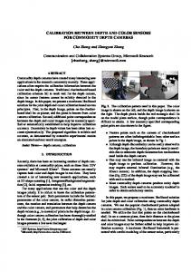
left monitor left camera
color stripe projector baseline b
right monitor
right camera
Figure 4: Principle of the stereo system using active color illumination.
Fortunately, we must not determine either object colors or projected colors, when using stereo vision [14, 15]. The colors obtained by superimposing object colors with the color coded illumination are identical in both images. Therefore, the pixels in the images can be matched without any additional knowledge about the object colors or the light colors, respectively. The principle of the stereo arrangement using active color illumination is outlined in Fig. 4. We projected a rainbow like color spectrum onto the scene. Every row of length n in the color spectrum SRGB was generated using the equations G G i SR = sin Ê ◊ p ˆ ◊ Ê max - 1ˆ + max , Ën ¯ Ë 2 ¯ 2 G Ê 2 i ˆ G SG = sin Á Ê + ˆ ◊ p ˜ ◊ Ê max - 1ˆ + max , for i = {0, K, n}, ¯ ËË 3 n¯ ¯ Ë 2 2
(7)
G Ê 4 i ˆ G SB = sin Á Ê + ˆ ◊ p ˜ ◊ Ê max - 1ˆ + max , Ë ¯ Ë ¯ Ë 3 n ¯ 2 2 where i denotes the column position in the spectrum image and Gmax denotes the maximum intensity value in every color channel. The color spectrum was synthetically generated using the equations mentioned above. Afterwards, a slide representing this synthetic color stripe code was exposed by using a scanner for color reversal films. This slide is projected onto the objects using a standard slide projector. The two stereo images are acquired with color CCDcameras. Using the standard geometry the epipolar lines match the image line. Therefore, the matching process can be simplified as corresponding pixels can only be found in the same row in both images. To take advantage of the structured illumination we chose the chromatic Block Matching algorithm for stereo matching, because it considers the color coding best.
143
3.1 Experimental results with synthetic images The quality of a stereo algorithm can hardly be evaluated if exclusively real images and the computed disparity maps are investigated. Often there does not exist enough information to predict the correct disparity values, particularly in dense disparity maps. Opposed to this, the correct depth map and an integer map representing the disparity values can be generated when using synthetic images and a stereo simulator. Thus, the quality of a matching algorithm can be easily checked by comparing the computed disparity map with the ideal one. Now we present some results using a synthetic image pair, we name "CUBE", of size 512 ¥ 512 pixels. The imaging geometry was determined placing the 90 cm high cube in a distance of 3 m to the virtual camera with focal length f = 50 mm. The direction of the light source was determined as LXYZ = (2, 3, -4). The right stereo image was generated with a horizontal camera displacement of 50 cm (see Fig. 5). The matching of surface patches with uniform shading and without texture is ambiguous. Fig. 5 shows the computed disparity map obtained when applying the Block Matching algorithm to the original images. Several mismatches occurred due the ambiguity of the intensity values of the cube. As stated above the ambiguities can also be solved by adding a synthetic texture to the scene. We superimposed the synthetic images with the color spectrum introduced in the previous section. The resulting disparity map is shown in Fig. 6. Additionally, we compared both disparity maps to the ideal disparity map generated by the stereo simulator. The computed results improved significantly when using structured light (see Fig. 6 and Tab. 2). The image "CUBE" was chosen to clarify the effect of colored light to the matching problem. Of course the results can not be used to predict similar improvements for real scenes. We generated a more complex synthetic stereo image called "BEETHOVEN" of size 512 ¥ 512 pixels. The selected 3-d object represents a bust of Beethoven and consists of 4500 polygons. The imaging geometry was determined placing the 35 cm high bust in a distance of 75 cm to the virtual camera with focal length f = 50 mm. The surface was shaded due to perfect Lambertian reflection and the intensities were interpolated along the edges of the polygons with Gouraud shading. The direction of the light source was determined as LXYZ = (-1, 2, -4). The right stereo image was generated with a horizontal camera displacement of 10 cm (see Fig. 7).
Figure 5: The synthetic gray value stereo images "CUBE" and the reconstructed disparity map.
144
Difference (in pixel) 0 1 ≥2
Intensity images (%) 7.9 12.2 79.8
Color images (%) 62.2 25.8 12.0
Table 2: Distribution of the matching errors (in percentage) for the gray value images and for the images superimposed with the color spectrum.
Figure 6: Disparity map computed for the stereo image superimposed with the color spectrum.
We computed the differences between the ideal disparity map and the disparity maps computed when applying the Block Matching algorithm to the gray value images and to the images superimposed with the color spectrum. Results are shown in Tab. 3. Furthermore, we carried out some experiments to investigate the robustness of the new technique concerning noise, variation in contrast, and variation in intensity between the left and the right stereo image. The results of these experiments will give a closer prediction of what can be expected from real images. The first experiment investigates the sensitivity of the matching results regarding noise in one of the images. Therefore, Gaussian noise of s = 10.0 was added to the intensity function of the right image (before projecting the color code). The Block Matching algorithm was applied to the intensity images and to the images superimposed with the color spectrum. The differences between the ideal disparity map and the computed disparity maps were determined. Results are shown in Tab. 4. Second we investigated the sensitivity of the matching results regarding variation in contrast between both images. Therefore, the intensity I R of the right image was transformed to I ¢ R (before projecting the color code) using the equation 3 1 I ¢ R = ◊ I R + ◊ Gmax , (8) 4 8
Figure 7: Left and right intensity stereo image representing a bust of "BEETHOVEN".
145
Difference (in pixel) 0 1 ≥2
Intensity images (%) 59.6 34.0 6.3
Color images (%) 63.3 31.8 4.8
Difference (in pixel) 0 1 ≥2
Table 3: Distribution of the matching errors (in percentage) for the gray value images and for the images superimposed with the color spectrum.
Intensity images (%) 39.8 42.5 17.7
Color images (%) 44.3 43.5 12.2
Table 4: Distribution of the matching errors (in percentage) when one the images is disturbed with Gaussian noise of s = 10.0.
where Gmax denotes the maximum intensity. The Block Matching algorithm was applied to the intensity images and to the images superimposed with the color spectrum. The differences between the ideal disparity map and the computed disparity maps were determined. Results are shown in Tab. 5. The third experiment was carried out to investigate the sensitivity of the matching results regarding differences in intensities between both images. Therefore, the intensity I R of the right image was transformed to I ¢ R (before projecting the color code) using a gamma correction of 1
Ê I ˆc I ¢ R = Á R ˜ ◊ Gmax , Ë Gmax ¯
(9)
where Gmax denotes the maximum intensity and c = 1.5 . The Block Matching algorithm was applied to the intensity images and to the images superimposed with the color spectrum. The differences between the ideal disparity map and the computed disparity maps were determined. Results are shown in Tab. 6. Several additional investigations were carried out for synthetic images. Unfortunately, we can not present further details due to limited space. In summary, we found that the matching results always improved when a color spectrum is projected onto the scene. Furthermore, the results are rather robust concerning noise, contrast variations, and intensity variations.
Difference (in pixel) 0 1 ≥2
Intensity images (%) 14.7 20.9 64.4
Color images (%) 37.7 42.6 19.7
Table 5: Distribution of the matching errors for images with different contrast (in percentage).
Difference (in pixel) 0 1 ≥2
Intensity images (%) 9.6 18.4 72.0
Color images (%) 28.6 36.7 34.7
Table 6: Distribution of the matching errors for images with different intensities (in percentage).
146
(a)
(b)
(c)
(d)
Figure 8: (a) Gray value representation of the real color stereo image "RELAXING JACK", (b) a shaded representation of the reconstructed scene, (c) the computed depth maps without (left) and with active illumination (right), (d) the difference (scaled) between both depth maps.
3.2
Experimental results for real images
Since the projection of color codes onto the scene considerably improves the quality of the matching results for synthetic images we applied the same technique to real images. We applied the Block Matching algorithm to a color stereo image named "RELAXING JACK" (see Fig. 8 (a)). The computed depth map, that was obtained by triangulation from the disparity map, shows a defect beneath the head (magnified section). An other artifact occurs at the bottom part of the arm-chair, although this uniform shaded section is quite small (see Fig. 8 (c)). In another experiment the color spectrum was projected onto the same scene. The artifacts that occurred when using the original color images, do not show up (see magnified sections in Fig. 8 (c) right). Visualizing the difference of the two depth maps (see Fig. 8 (d)) points out more distinctions. Additionally, Fig. 8 (b) shows the reconstructed scene mapped with the texture of the right image. The experiments mentioned above show a considerable improvement in the matching results for synthetic and for real images when active color illumination is utilized. Regarding other investigations with structured illumination the main advantage of this method is, that it deals with only one pair of images. Thus, the method can also be applied to moving or non-rigid objects.
4
Conclusion
A combination of two approaches for dense stereo matching has been presented. The first approach uses an image pyramid model and a hierarchical implementation of Block Matching for color stereo images. It has been shown that the quality of the
147
matching results can be improved with this hierarchical approach. The computing time is reduced by a factor of two at the same time. Furthermore, the hierarchical approach can be implemented very efficiently in parallel to achieve high speed execution. The second approach we presented uses active color illumination for stereo matching. We showed the benefit of the approach for synthetic and for real images. The quality of the matching results always considerably improved when employing active colored illumination, particularly in homogenous regions. This holds for every dense stereo technique. We used the combination of the hierarchical approach with active color illumination to produce high quality results. Additional tests and investigations are necessary for a more detailed investigation of the technique. Currently, this is under investigation and further results will be presented soon. In summary, we should like to emphasize that active colored illumination always serves to improve stereo matching results. Therefore, we believe that more precise results can be efficiently obtained in dense stereo matching when combining hierarchical chromatic Block Matching with the active color illumination approach.
Acknowledgment This work was funded by the Deutsche Forschungsgemeinschaft (DFG). Furthermore, we thank K. Spiller for helpful assistance to the tests and to the implementations.
References [1]
Jordan III, J.R., Bovik, A.C.: Using chromatic information in dense stereo correspondence. Pattern Recognition 25, 367-383 (1992).
[2]
Okutomi, M., Yoshizaki, O., Tomita, G.: Color stereo matching and its application to 3-d measurement of optic nerve head. Proc. 11th IAPR Int. Conf. on Pattern Recognition ICPR´93, the Hague, the Netherlands, vol. I, pp. 509513, 1992.
[3]
Koschan, A.: Dense stereo correspondence using polychromatic block matching. Proc. of the 5th Int. Conf. on Computer Analysis of Images and Patterns CAIP'93, D. Chetverikov, W. Kropatsch (eds.), Budapest, Hungary, pp. 538-542, 1993.
[4]
Vriesenga, M., Healey, G., Peleg, K., Sklansky, J.: Controlling illumination color to enhance object discriminability. Proc. Int. Conf. on Computer Vision and Pattern Recognition CVPR´92, Champaign, Illinois, pp. 710-712, 1992.
[5]
Murase, H., Nayar, S.K.: Illumination planning for object recognition in structured environments. Proc. Int. Conf. on Computer Vision and Pattern Recognition CVPR´94, Seattle, Wa., pp. 31-38, 1994.
[6]
Kang, S.B., Webb, J.A., Zitnick, C.L., Kanade, T.: A multibaseline stereo system with active illumination and real-time image acqisition. Proc. 5th Int. Conf. on Computer Vision CVPR´95, Cambridge, Ma., pp. 88-93, 1995.
148
[7]
Marr, D.: Vision - A Computational Investigation Into the Human Representation and Processing of Visual Information. New York: Freeman & Co 1982.
[8]
Tanimoto, S., Pavlidis, T.: A hierarchical data structure for picture processing. Computer Graphics and Image Processing 4, 104-119 (1975).
[9]
Kropatsch, W.G.: Properties of pyramidal representations. Computing Suppl. 11, 99-111 (1996).
[10] He, Z.L., Liou, M.L.: Design trade-offs for real-time block-matching motion estimation algorithms. Proc. 2nd Asian Conf. on Computer Vision ACCV´95, Singapore, vol. I, pp. 305-309, 1995. [11] Koschan, A., Rodehorst, V.: Towards real-time stereo employing parallel algorithms for edge-based and dense stereo matching. Proc. of the IEEE Workshop on Computer Architectures for Machine Perception CAMP´95, Como, Italy, pp. 234-241, 1995. [12] Sasse, R.: Bestimmung von Entfernungsbildern durch aktive stereoskopische Verfahren. Braunschweig, Wiesbaden: Vieweg 1994. [13] Knoll, A., Sasse R.: An active stereometric triangulation technique using a continuous colour pattern. In: W. Straßer, F. Wahl (eds.): Graphics and Robotics. Berlin: Springer 1995, pp. 191-206. [14] Koschan, A., Rodehorst, V., Spiller, K.: Color stereo vision using hierarchical block matching and active color illumination. Proc. 13th Int. Conf. on Pattern Recognition ICPR´96, Vienna, Austria, vol. I, pp. 835-839, 1996. [15] Klette, R., Koschan, A., Schlüns, K.: Computer Vision - Räumliche Information aus digitalen Bildern. Braunschweig, Wiesbaden: Vieweg 1996.