Department of Computing Science and Mathematics. University of Stirling. An
Analysis of Planarity in Face-Routing. Marwan Fayed, David Cairns, and Hussein
...
Department of Computing Science and Mathematics University of Stirling
An Analysis of Planarity in Face-Routing Marwan Fayed, David Cairns, and Hussein T. Mouftah
Technical Report CSM-184 ISSN 1460-9673
August 2010
Department of Computing Science and Mathematics University of Stirling
An Analysis of Planarity in Face-Routing Marwan Fayed, David Cairns, and Hussein T. Mouftah Department of Computing Science and Mathematics University of Stirling Stirling FK9 4LA, Scotland Telephone +44 1786 467 421, Facsimile +44 1786 464 551 Email {mmf,dec}@cs.stir.ac.uk,
[email protected]
Technical Report CSM-184 ISSN 1460-9673
August 2010
Abstract In this report we investigate the limits of routing according to left- or right-hand rule (LHR). Using LHR, a node upon receipt of a message will forward to the neighbour that sits next in counter-clockwise order in the network graph. When used to recover from greedy routing failures, LHR guarantees success if implemented over planar graphs. This is often referred to as face or geographic routing. In the current body of knowledge it is known that if planarity is violated then LHR is guaranteed only to eventually return to the point of origin. Our work seeks to understand why a non-planar environment stops LHR from making delivery guarantees. Our investigation begins with an analysis to enumerate all node configurations that cause intersections. A trace over each configuration reveals that LHR is able to recover from all but a single case, the ‘umbrella’ configuration so named for its appearance. We use this information to propose the Prohibitive Link Detection Protocol (PDLP) that can guarantee delivery over non-planar graphs using standard face-routing techniques. As the name implies, the protocol detects and circumvents the ‘bad’ links that hamper LHR. The goal of this work is to maintain routing guarantees while disturbing the network graph as little as possible. In doing so, a new starting point emerges from which to build rich distributed protocols in the spirit of protocols such as CLDP and GDSTR.
Acknowledgements We thank Ben Leong and Hongyang Li, and for their insightful comments, the reviewers. This work was supported by the Scottish Informatics and Computing Science Alliance, and the Natural Sciences and Engineering Research Council of Canada.
1
Introduction
The construction of network subgraphs appropriate for position-based (or geographic) routing protocols has, to date, remained a complex problem. These subgraphs are needed to recover from the local minima problem (see [1]) that prevents delivery and plagues position-based protocols. Network subgraphs constructed for recovery using only 1-hop information risk inaccuracies that cause routing failures [2, 3]. One remedy is to allow nodes to cooperate. If permitted, cooperating nodes may construct a network subgraph that remedies any inaccuracies [3, 4, 5, 6]. Yet the resources needed to power the many rounds of communication between nodes, risks being prohibitive in such a resource-constrained environment. The ideal wireless network subgraph would guarantee successful delivery while a) needing only 1-hop information and b) be able to acquire such information passively. Traditionally, position-based routing protocols construct subgraphs (herein referred to as just ‘graph’) from available links in somewhat of a bottom-up fashion. Generally the idea is to extract a specific type of graph from the available nodes and links in the network. During the setup of such graphs each node evaluates available links to find those that preserve some global properties. Planar graphs [7] and k-spanners [8] are two such examples. The analogous question would be to ask, “what is the set of edges that must be preserved to guarantee a given feature in the graph?” Our work is motivated by the opposite question, “What is the minimum set of edges that must be deleted while still providing guarantees?” Without sacrificing the scalability and success of position-based routing, the goal of this work is to disturb the network as little as possible. To this end it is necessary to understand the causes for a position-based routing protocol to fail to recover from local minima and deal with those causes directly. We believe this paper is the first work in that direction. In this paper we investigate routing according to left- or right-hand rule (LHR). Using LHR, a node, upon receipt of a message, will forward to the neighbour that sits next in counterclockwise order in the network graph. (Alternatively, clockwise order if using right-hand rule.) When used to recover from greedy routing failures, LHR guarantees success if implemented over planar graphs; for this reason it is often called ‘face-routing’. We note, however, that if planarity is violated then LHR is only guaranteed to eventually return to the point of origin. Our work seeks to understand and correct the underlying causes of these failures. We have chosen LHR for three reasons. First, it is most prevalent in position-based routing literature and hence well-studied. Second, it is a simple rule requiring little-to-no overhead. Finally, the ideal network graph remains elusive. To re-iterate, we envision the ideal graph as overcoming the inaccuracies that lead to routing failures; as one that results from knowledge of the 1-hop neighbourhood; and as one where each node transmits a constant number of messages. We begin with a provable enumeration of the possible types of intersections in a unit-disc graph (UDG), within which any two nodes are neighbours if separated by a maximum distance of one unit. Our analysis reveals that only three types of intersections are possible. A trace of face-routing over each intersecting neighbourhood further reveals that in only one of these configurations does LHR fail to recover: We call this the ‘umbrella’ configuration, so named for its appearance. The umbrella configuration naturally hides links and nodes from a face-routing traversal, partitioning the graph with respect to the traversal. Unless there appears some other non-local route to join these partitions, potential routes will be unavailable to any face-routing technique. We use this information to propose the Prohibitive Link Detection Protocol (PLDP). PLDP identifies the umbrella configuration and removes from it a single link. In doing so, PLDP provides a graph over which any face-based method may provably guarantee delivery using
1
standard geographic and face-routing rules. In our evaluation we compare the setup and quality of PLDP graphs with CLDP and GDSTR using Netsim2 [5, 9]. Our simulation results demonstrate that PLDP performance is similar to current face-routing schemes. Where PLDP separates itself is in the number of messages required to setup the network: Most nodes will need to generate no setup packets and from those that do, a very small number of packets is needed. Our evaluation will show that the small number of setup packets are indicative of the infrequency of the umbrella configuration, the consequence of which is that PLDP is able to preserve most of the links in the original network graph. In a manner of speaking our evaluations suggest that traditional face-routing schemes may be ’over-solving” the problem by planarizing networks. On the surface this seems an unfair comparison since both GDSTR and CLDP operate without the unit disc assumption. We emphasize that our goal is to provide a better understanding of the underlying motivations for such distributed protocols and, in doing so, provide a new starting point for distributed protocols that may out-perform those of the current generation. PDRP may be unable to compete directly due to the unit disc assumption, but we will show that it provides a novel direction from which to build. In summary, this paper seeks to provide a basis that is a lateral shift away from planarity so that better cooperative position-based protocols may be built. By investigating the underlying causes for failure, planarity is shown to be unnecessary in the majority of cases. We propose PLDP as a means to relax constraints on the network graph while preserving the promise of local face-routing techniques.
2
Related Work
The most prominent and best known recovery algorithms route around the hole face (or perimeter) in the planar subgraph. This method is equivalently known as face routing [10, 11] and perimeter routing [12]. Face routing was first proposed by Bose et al. in [10] with some theoretical bounds. Karp et al. independently proposed an identical mechanism in [12] but with work on a MAC-compatible implementation. Variants have since emerged addressing, for example, theoretical bounds in [13, 14, 15]. In [16], face-routing is augmented into a “select-and-protest” reactive protocol in order to reduce the information required to planarize the graph. Wireless network graphs may consist of intersecting edges so it is necessary for planar subgraph methods to prune edges from the network graph so that it is planar while remaining connected. Gabriel Graphs (GG) and Relative Neighbourhood Graphs (RN G) are planar graphs whose constructions are localised, a characteristic particularly suitable to sensor environments. Intersecting edges are eliminated by connecting pairs of nodes through witness nodes, if such a node exists in a common region. It has since been shown that ‘Hello’ messages may hinder network performance [17]. This is addressed in face-routing directly by [18] and more generally in [19, 20, 21]. Further work in [22] reduces the path length during the recovery phase. These distributed constructions are unable to resolve links broken by obstacles or interference [23,24]. Recent breakthroughs have begun to surmount the impracticalities of face-routing while maintaining delivery guarantees [4, 5]. The Greedy Distributed Spanning Tree Protocol (GDSTR) algorithm in [5] builds on the fact that any message can be successfully delivered via depth-first search if the network is connected via a spanning tree. This fact alone does not solve the problem: GDSTR provides optimizations to reduce the otherwise inefficient delivery requiring up to 2n − 3 hops. The authors in [5] describe a new type of spanning tree, the hull tree, to route more efficiently. A hull tree is a spanning tree with one added piece of information: each node records the convex hull that contains all of its descendants in the tree. (The convex hull of a set of points is 2
the smallest polygon that contains all the points.) In GDSTR forwarding occurs greedily, as do most position-based protocols. If a message reaches a void, a recovery mode is initiated where convex hulls are used to determine the regions of the network that contain unreachable destinations. This information is used by GDSTR to route along the spanning tree to forward to the appropriate convex hull. If a node is found en route that is closer to the destination than the node where the message was stuck, then GDSTR returns to greedy forwarding. GDSTR is known to scale well as the neighbourhood size grows. Furthermore, the use of multiple hull trees adds fault-tolerance to the network and if multiple trees are rooted at opposite ends of the network, routing efficiency improves. The Cross-Link Detection Protocol (CLDP) proposed in [4], and later improved in [25], circumvents voids by face-routing. It uses left-hand rule over a planar subgraph of the network; its design however, is motivated by the observation that routing difficulties in planar subgraph methods arise, in part, due to the constructions themselves. (Recall from previous that successful local planar subgraph constructions rely on the unit disc graph.) For this reason, CLDP proposes an alternate construction of planar subgraphs that assumes only that links are bidirectional. CLDP operates in a distributed fashion, exchanging some localised operation for accurate information. The idea behind CLDP is that each node is able to probe the vicinity for intersecting links. A probe packet is initialised with the endpoints of the first link to be probed and forwarded according to left-hand rule. The probe eventually returns to its point of origin with a vector of the path taken. This information is shared with nearby nodes to prune links appropriately. To avoid the slow process of scheduling serial probes by neighbouring nodes, a system for concurrent probing is proposed. Concurrent probing is achieved by implementing a mechanism to ‘lock’ links so that no more than one link is removed at a time from any vicinity. CLDP is one of very few protocols to have been implemented on testbeds [4]. The associated communication complexities and storage costs revealed in this process (see [2,5]) are motivation to develop alternative approaches to guarantee delivery. A more recent approach is to think about how the network might embed onto a different physical space. One such work appears in the FaceTrace project [6] which imagines that nodes in the network sit on a high-genus topological surface, such as a torus. It is a novel technique that extracts onto these surfaces faces from the network itself, rather than faces associated with local minima in the network. In doing so, planarity emerges naturally. In simulation FaceTrace exhibits routing quality of a very high order but the setup cost is reported to be similar to those of GDSTR, numbering many orders of magnitude. Protocols such as CLDP and GDSTR, in order to be feasible for physical networks, sacrifice efficiency for accuracy. CLDP requires high-complexity negotiations within each neighbourhood in order to prune appropriate links. GDSTR reduces the messaging complexity but must broadcast information to construct and maintain its hull trees. It remains an open question whether such trade-offs are a necessity. The work in [16] is a step in the right direction. Its recognition that there are available short-cuts when routing according to LHR is further evidence that the planarity assumption may be excessive. By contrast, in this work we show that there exists a locally constructed, non-planar graph construction over which face-based protocols guarantee success.
3
Links that Prohibit Routing Success
In the previous section we noted that routing according to right- or left-hand rule (LHR) alone, fails to provide a guarantee of success. Though this fact is well known, the reasons and circumstances under which delivery may fail are poorly understood. In this section we seek to investigate the limits imposed by intersections on face-based recovery. 3
a
d
D
b
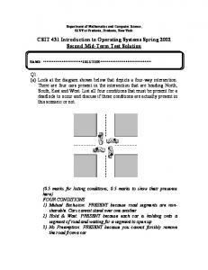
c Figure 1: Intersecting links between two pairs of nodes may impose any or all edges in a 4-gon. Our goal is to maximise the number of active edges in a wireless network graph while providing routing guarantees using LHR. In an attempt to relax planarity, currently required to guarantee the success of a traversal between two nodes, we must identify the causes for failure in an arbitrary graph. We focus this work on the unit disc graph (UDG), where all communication ranges are normalised. The UDG is appropriate since it limits potential routing options yet still poses a challenge to LHR routing. Our investigation begins with an enumeration of all of the types of intersections that may appear in the UDG.
3.1
An Enumeration of Intersection Types
Consider any two intersecting edges. We provide the edges ac and bd in Figure 1 for reference. The nodes a, b, c, d at the end points of these edges form a 4-gon (shown in Figure 1 using dashed lines). The question we ask is, which of the edges of the 4-gon may or may not be communicating links in the unit-disc graph? In order for at least one such edge to exist, we need to show that all four sides cannot be greater than both diagonals. Using cosine rule we know, (ac)2 = (ad)2 + (dc)2 − 2(ad)(dc) cos D.
(1)
If |ac| is less than or equal to 1, then (ad)2 + (dc)2 − 2(ad)(dc) cos D ≤ 1.
(2)
When D ≥ π2 , then cos D ≤ 0. In this case, (ad)2 + (dc)2 ≤ 1, which means (ad) ≤ 1 and (dc) ≤ 1. Thus, if an angle of the 4gon is right or obtuse, then both incident edges must exist in the UDG. (By contrast, incident edges when D < π2 may or may not exist.) This implies and restricts the possible configurations that allow intersections to three in number, all shown in Figure 2. The two cases where the nodes of intersecting edges produce a 4-gon with two obtuse angles is shown in Figures 2a and 2b, while the 4-gon containing a single obtuse angle is shown in Figure 2c. (It is impossible for a 4-gon to be constructed with three obtuse edges; and that edges incident to an acute angle may or may not appear in the unit-disc graph.)
3.2
The Prohibitive Link
The finite and small number of possible intersections allows us to carefully examine the behaviour of a left-hand traversal over all possible cases. A left-hand traversal is deemed successful 4
a a
obtuse
acute
b
a
acute
d d
acute
obtuse
c
d
obtuse
obtuse
b
obtuse
b
acute
acute
acute acute
c
c
(a) All edges of the 4-gon must (b) Edges bc, cd, da must exist. (c) Edges ab, ad must exist. exist. Figure 2: Possible 4-gons when edges ac and bd intersect in the UDG with dashed lines indicating edges that may or may not appear. a
b
a
d
c
(a)
a
b
c
d (b)
d
b
c
(c)
Figure 3: A unique face emerges from all but the ’umbrella’ shape, shown in (c). when it can identify a single unique face in an intersecting environment. We show in Figure 3 the traces corresponding to the three intersections in Figure 2. Traversals are shown using a dotted line. In the first two cases an LHR traversal succeeds in identifying a single face irrespective of the point of entry into the intersecting environment. (We show via inductive proof in Section 4 that the same holds true when intersections are composed together.) The ‘bad’ configuration occurs during a traversal of the intersection shown in Figure 3c. Here the different points of entry reveal that there are two faces with respect to LHR. This means there are two ways in which LHR may fail. The first is demonstrated by the dashed-dot-dash line originating at node d. (Entry at nodes a and b are analogous.) A traversal using left- or right-hand rule will never traverse edge ac while travelling through this intersection. Supposing c must be traversed in order to reach the destination, LHR will fail. The second possible failure occurs when an LHR traversal encounters this intersection first via node c in Figure 3c using the dashed line. LHR traverses the inside of the triangle 4abd and exits without ever seeing edges that protrude from the outside of the triangle. As before, any such edges leading to the destination may be overlooked by an LHR traversal. Referring back to Figure 2c this case occurs when there are three acute angles and when only the edges of the 4-gon incident to the obtuse angle appear. This represents the case where network node a communicates with b, c, d, and b with d; node c communicates only with a. We call this case the umbrella configuration for its appearance. The cause of both failures lies in the relationship between 4abd and ac in Figure 3c: There exists an edge from the triangle that is accessible only from inside the triangle. In other words, a traversal around the inside or the outside of the triangle fails to encounter all edges leading to the triangle. Both failures are solved by removing any of the edges that form the triangle. The easiest of these to identify and remove from the network graph is the edge of the triangle 5
a
d
b
c
Figure 4: Removing prohibitive link bd allows LHR to traverse all edges. that forms the intersection in the umbrella configuration. In Figure 3c this link is represented by bd. We call this the prohibitive link. The prohibitive link is identified by the only node that is able to see all four nodes that anchor the umbrella configuration. In Figure 3c this responsibility falls on node a. It looks for intersections consisting of two links. The first link is formed by itself and an immediate neighour, with subsequent links formed between two immediate neighbours. Referring again to Figure 3c, node a evaluates the intersection of ac with bd. We revisit this subject and build a networking protocol in Section 4. Before closing this section the outcome following a removal of the prohibitive link from the umbrella configuration is demonstrated in Figure 4. The intersection that was the umbrella configuration is reduced to a planar set of edges easily navigated by left- or right-hand rule.
3.3
A Note on the Sufficiency of Prohibitive Links
In our introduction we stated that this work was motivated by the desire to find the minimal set of edges necessitating deletion while preserving certain guarantees. (In particular, we guarantee delivery using face-routing schemes.) We note here that the set of prohibitive links to be deleted is sufficient, but it may be unnecessary to delete all of the links in the set. The minimal set remains an open problem.
c
q p
b
d
a
Figure 5: Removal of the prohibitive link is only sufficient. An example of where it is sufficient but unnecessary to delete a link is shown in Figure 5. Node a recognises prohibitive link bd in its neighbourhood. Removal of bd guarantees that
6
all links in and out of the intersecting nodes will eventually be encountered. With respect to the local neighbourhood it is necessary to remove the prohibitive link. However the exitence of alternate paths outside of a neighbourhood, as shown in Figure 5 through nodes p and q, suggest that it may be unnecessary to remove the prohibitive link. We will see in our evaluations in Section 5 that the occurrence of umbrella configurations is so infrequent that this trade-off between global knowledge and local decisions may not even be worth considering. In the next section we use our knowledge of the prohibitive link to construct the prohibitive-link detection and routing protocol.
4
Prohibitive-link Detection and Routing Protocol (PDRP)
We have enumerated all possible intersections in the unit-disc graph and identified the type of intersection with the link that prohibits successful delivery when routing according to right- or left-hand rule. In this section we present a Prohibitive Link Detection Protocol (PLDP) and show its correctness.
4.1
PLDP Overview
Most wireless protocols construct network graphs to guarantee delivery. The goal of PLDP is to remove from the network graph as few links as needed to guarantee routing. To better describe PLDP we assume a static graph where each node is assigned a coordinate in a 2-dimensional Euclidean system. We assume that the graph is connected and that all links are bi-directional. PLDP functions adequately in a mobile space provided that changes in position occur over a greater time-frame than is required to re-evaluate local prohibitive links and transmit local updates. In this work communication range is fixed and uniform across all nodes.
a
a
om
it d
tb mi
,e
d
om
it
b
o
d
b e
b
e
c
c
(a) Before detection phase.
(b) Following detection phase links db and eb omitted.
Figure 6: Local neighbourhood from viewpoint of node c, before and after the PLDP detection phase. The face-routing family of protocols preserve their delivery guarantees in PLDP graphs. During their normal operation nodes route in a greedy fashion and forward messages to the neighbour that most reduces the distance to the destination. Where no such neighbour exists a message is deemed ‘stuck’ in a local minima and is forwarded according to left- (or right-)hand
7
rule. (The node initially selected is the first to appear left, or right, of the line segment from the current location to the destination.) The first node found that sits closer to the destination than the ‘stuck’ location returns to the greedy forwarding phase. The correctness of PLDP and its ability to guarantee delivery to the destination is discussed in Section 4.2. During the PLDP detection phase each node inspects its neighbourhood using neighbour positions reported in ordinary ’hello’ packets. Each node evaluates intersections within range and flags any three neighbours that compose an umbrella configuration, as described in Section 3.2. Once sufficient information is compiled a node sends an notification packet to the neighbours that anchor prohibitive links. Notification messages exchanged between nodes consist of either a delete or an insert instruction. As is suggested by its label, a delete deactivates a prohibitive link at the anchors of the link. Similarly an insert instruction reactivates a link previously deemed prohibitive. This allows for corrections as the network state changes. We emphasize that PLDP takes a passive approach when looking for the recovery subgraph: In contrast to the ’active’ approach taken by protocols such as CLDP and GDSTR, PLDP sends instruction messages only upon witnessing an umbrella configuration, and only to the neighbours that anchor the prohibitive link. The reduction in overall messaging is evaulated in Section 5.4. The detection phase is demonstrated in Figure 6. In Figure 6a, node a determines that two intersections in its vicinity contain prohibitive links, those links being bd and eb. Nodes b, d, and e have no knowledge of node c’s existence. The responsibility falls on node a to inform neighbours of their prohibitive links. Moving to Figure 6b, node a instructs each of d and e to ignore their links to b during recovery; similarly node a instructs b to omit links to d and e. Alternatively, notifications may be avoided entirely by producing and sending ’hello’ notification packets that include neighbour information. Having been provided a 2-hop view of its neighbourhood a node can see all of the information it needs to identify prohibitive links (albeit at the cost of a larger ’hello’ packet).
4.2
Statement of Correctness
Having identified and removed prohibitive links in umbrella configurations, we show in this section that PLDP will successfully route a message between two nodes if a path exists. We remind our reader that during the routing phase of PLDP, any standard position-based routing technique consisting of greedy + face-routing recovery may be implemented. The following argument progresses first by defining the graph embedding so that we might state our claim. We first establish connectivity of the network embedding, and then show correctness by tracing a face-routing traversal within its intersections. Definition 4.1 Let G be an embedding of a graph. We define G0 = U DG(G) ∩ U mb(G), where U DG(G) is the unit-disc graph over G and U mb(G) is the subgraph of G where umbrella intersections are removed. Proposition 4.2 If U DG(G) is connected, then so too is G0 . Proof (Sketch). We begin with an umbrella configuration in a unit disc graph. The prohibitive link is only removed when there is an alternate path remaining between all nodes in the neighbourhood. Thus, removal of the prohibitive link cannot disconnect the nodes in the umbrella configuration. Any connected component in U DG(G) remains connected in G0 .
Having shown connectivity we can now inspect traversals in the network embedding. 8
Proposition 4.3 We claim that in G0 , a traversal T , consisting of left-hand rule with memory, will find and traverse a unique face. Proof. We prove by induction on the neighbourhoods witnessed by T . Consider the first neighbourhood, k0 , visible to starting node v. If no intersection is visible to v then the next edge in T is trivial. If, however, an intersection exists in k0 then it must be in the form depicted in either of Figures 7a or 7b (see Section 3.1 for proof). We evaluate both cases below.
d
d m
q
p
n
t
r
o (a)
s (b)
Figure 7: Once prohibitive links are omitted, two possible contentious configurations remain. 1. Consider the intersection in Figure 7a. For any v ∈ {m, n, o, p} and destination d, if vd intersects with no local edges (ie. vd does not pass through quadrilateral (mnop)) then the next left edge - and thus first edge in the current face - is trivial. If, however, vd does pass through (mnop) as shown in Figure 7a then there are two cases: v = n The starting vertex is situated in the quadrilateral such that a single vertex sits left − → of vd and two vertices sit on the right. In Figure 7a this case is represented by v = n. Node n forwards to m. Both mo and mp intersect with nd, the line segment from the destination to the point where T started, so T will escape this neighbourhood → when m chooses the next CCW edge from − mp. v = o The starting vertex is situated in the quadrilateral such that a single vertex sits right − → of vd and two vertices sit on the left. In Figure 7a this case is represented by v = o. Here, too, o forwards to m and m chooses the next CCW edge from mp. In either case, the face of interest begins at vertex m where a cycle, if traversed, will be declared. 2. Consider the intersection in Figure 7b. Let starting node be v ∈ q, r, s, t and destination d sit such that rd intersects qs and sd intersects rt. The trivial case is v = q. Three cases remain: v = r The starting vertex is situated in the quadrilateral such that a single vertex sits left − → of vd and two vertices sit on the right. In Figure 7b this case is represented by v = r. r forwards to q where T will escape the neighbourhood. (Recall that when T intersects with vd, T switches faces.) In this case the cycle will be detected at r. v = s The starting vertex is situated in the quadrilateral such that a single vertex sits right − → of vd and two vertices sit on the left. In Figure 7b this case is represented by v = s. s forwards along sq where T escapes the neighbourhood. On its return, T will detect a cycle at s since node t will avoid the edge sq since it was traversed previously. 9
v = t The starting vertex is situated in the quadrilateral such that all three vertices sit − → left of vd. In Figure 7b this case is represented by v = t. Here, T traverses tr, rq before its escape from q. (Note that qs is not a valid edge since it intersects the edge previously traversed, tr. T will detect this cycle at node t. Assume now that for any neighbourhood, ki , traversal T exits on the same face on which it enters. We show that for neighbourhood ki+1 traversal T exits on the same unique face on which it enters. Referring once more to Figure 7, there are two types of neighbourhoods to consider. Those intersections whose endpoints join into a quadrilateral such as in Figure 7a require little consideration. For any entry point m, n, o, p on the quadrilateral, T will exit on the outside of this neighbourhood. Similarly in Figure 7b, traversals entering on {q, r, s} are trivial. We focus on traversals of T that reach node t. From t the next CCW edges in T are {tr, rq} since qs intersects tr. From q, T is forwarded along the next CCW edge.
Corollary 4.4 For any G0 , a traversal, T , consisting of left-hand rule with memory, guarantees a path will be found provided a path exists, or complete the face if no path exists. Proof. We know that for a set of unique faces (ie. no intersections) in an embedding, that a left-hand traversal from source to destination is guaranteed to find a path provided one exists. Thus T , which finds sets of unique (non-intersecting) faces will find a path if it exists, or complete the face where no path exists.
Finally, we note that traversal T requires no memory to succeed. A trace with no memory through all examples reveals that T will escape from any intersecting neighbourhood via the same egress links as above. T will achieve this by traversing the remaining links in the quadrilateral formed by the intersection. PLDP overcomes drawbacks of existing methods. We show in the next section that an implementation of PLDP is also competitive with these methods.
5
Simulation Results
The previous section describes the PLDP protocol and asserts its correctness. We demonstrate the practical performance of PLDP via simulation in the sections that follow.
5.1
Experimental Design
So that we might better evaluate the performance of PLDP we have implemented PLDP into the netsim platform for geographic routing simulations used to evaluate GDSTR in [5] and GSpring in [9]. We compare PLDP primarily against two protocols. The first is CLDP [2, 4], a novel distributed planarization protocol that corrects for real-world events that violate the unit disc assumption. The second is GDSTR [5], also a distributed algorithm that reduces the high communication cost of CLDP but forces the network to cooperate as a whole. The comparison of PLDP against CLDP and GDSTR may seem somewhat unfair given that CLDP and GDSTR operate outside of the UDG model. Our intention, rather than to ’compete’
10
directly is to question the need for the one assumption on which all face-based routing techniques are based, that planarity is required for correct operation. For completeness we set our experiments against a backdrop that includes more conventional face-routing schemes. Evaluations of the PLDP and CLDP network graph are made using GPSR [12] and GOAFR [14, 15]. GPSR design and accomplishments have served as the foundation on which later efforts have been built; it has long been considered the baseline for benchmark performance, while GOAFR provides some optimal theoretical bounds. Finally, GDSTR is implemented with two trees.
Figure 8: A sample network containing 250 nodes with an average degree of ∼ 8. Simulation networks are composed of nodes placed uniformly in a space that is 1000 units squared; each node having a communication range of 100 units. Node density varies by increasing network size; neighbourhoods ranged from 4 to 16 nodes, on average. Each set of tests consisted of 5 runs, using the same five networks drawn from non-overlapping streams in each set of tests. A sample network with 250 nodes and an average degree of ∼ 8 appears in Figure 8. Our primary performance metrics are hop stretch and message overhead. The latter takes our discussion into an investigation of the frequency of the umbrella configuration. We begin first by demonstrating the success rate of PLDP.
5.2
Routing Quality
The success rate is measured as the fraction of messages that are correctly transmitted between source-destination pairs. Figure 9a shows the success rate of each protocol as a function of network density (ie. the average number of neighbours). We test the validity of the CLDP and PLDP subraphs by routing with GPSR and with GOAFR. Each protocol performs as expected, with all but greedy routing achieving 100% success. This further demonstrates that, despite containing intersections, it is possible for face-routing schemes to guarantee delivery without planarity.
5.3
Hop Stretch
Of greater interest is the story that emerges by looking at the affect of PLDP on hop stretch. Hop stretch is defined as the ratio of hops taken vs hops of the minimum path. We consider only those paths over which packets were routed during face-based recovery; this is to avoid the
11
5 1
none-greedy rng-goafr cldp-goafr cldp-gpsr gdstr2 pldp-gpsr pldp-goafr
4.5
0.6
Hop Stretch
Success Rate
4 0.8
none-greedy rng-goafr cldp-goafr cldp-gpsr gdstr2 pldp-gpsr pldp-goafr
0.4 0.2 0
2
4
6
8
10
12
3.5 3 2.5 2 1.5 1
14
16
0
2
Average Node Density
4
6
8
10
12
14
16
Average Node Density
(a) Delivery Rates.
(b) Hop Stretch.
Figure 9: Routing metrics when PLDP is combined with traditional routing schemes. distortion of results that would otherwise occur during the greedy phase (which is a common phase among all the methods tested).
3.5
none-greedy rng-goafr cldp-goafr cldp-gpsr gdstr2 pldp-w/memory
1 0.8
Hop Stretch
Success Rate
3
0.6 none-greedy rng-goafr cldp-goafr cldp-gpsr gdstr2 pldp-w/memory
0.4 0.2 0
2
4
6
8
10
12
2.5 2 1.5 1
14
16
0
Average Node Density
2
4
6
8
10
12
14
16
Average Node Density
(a) Delivery Rates.
(b) Hop Stretch.
Figure 10: Routing metrics of PLDP graphs after memory is added to GPSR packets. Observations for hop stretch are shown in Figure 9b. In this figure we plot for a PLDP with no changes to the routing protocols overtop, namely GOAFR and GPSR, and labeled accordingly. Though delivery guarantees remain, the performance of both routing schemes is noticeably worse during the recovery phases over PLDP graphs than it is over planar graphs. In the best case scenario, routing over PLDP graphs during recovery takes 1/3rd greater number of hops than the next best scheme tested. Why is this, and is there anything that can be done? To understand the cause we refer back to Figure 3b, in which we trace an LHR traversal. In this ’open’ intersecting environment an LHR traversal that begins at node b and exits at node a requires 7 hops to escape. By contrast, were this region planarized then an LHR traversal requires 3 hops1 . To resolve this issue we look to the statement of correctness provided in Section 4.2. The case was proved for messages that maintain a record of the links traversed so that LHR can avoid 1
The overall cost to a path stretch is much lower than would appear since the portion of time a packet sends in recovery is much lower than the portion of time that a packet sends in greedy mode.
12
next hops that intersect with previous hops. In our evaluations up to this point we have tested unaltered routing protocols over the PLDP graph, a case also addressed in Section 4.2. Specifically this means that packets have no memory of where they have been so many intersecting links will be traversed, only to return later along the same link in the opposite direction. A noticeably different picture emerges if we record the recovery path and allow the routing protocol to skip past those links that would intersect previously traversed links. The effect of this “with memory” approach is demonstrated in Figure 10. First, in Figure 10a we can see the aforementioned change has no effect on delivery, as predicted previously. More interestingly is the difference in hop stretch. In Figure 10b we plot GPSR with memory over a PLDP graph. Noting the change in range along the y-axis, we can see that the hop stretch along the PLDP graph has been diminished by roughly 1/2.
a
b
c
d
Figure 11: When packets record traversed links, nodes can substantially reduce hop counts. So that our readers may clearly understand what is happening we point to Figure 11. A packet enters the intersecting region at node b who, according to LHR forwards to node d, who then forwards to a. Node a sees that the next link in counter-clockwise order ac intersects with link bd, previously seen by this packet. In this example a packet escapes the intersecting region using 1 fewer hops than if the region had been planarized. Figures 9 and 10 provide evidence that planarity may be ’over’ solving the challenges faced by face-routing schemes. Next we evaluate the messaging cost associated with the setup and maintenance of the PLDP graph.
5.4
Message Cost
It is difficult, though necessary, to compare the setup of PLDP graphs with those setup by CLDP and GDSTR. The difficulty arises because of the difference in assumptions and goals: PLDP in its current form relies on the unit-disc assumption, whereas CLDP and GDSTR make none. Furthermore CLDP strives to provide planarity while overcoming some real-world challenges that include, for example, uni-directional links. The comparison is necessary since, for all of their achievements, face-based protocols rely on the underlying assumption that planarity is required for guaranteed delivery. PLDP graphs recognise that this assumption is stronger than necessary. Presumably, if we can reduce the set of undesired events then we can create more efficient real-world protocols. We plot the total number of messages sent in a network, on average, on log scale in Figure 12. The results obtained for CLDP and GDSTR are consistent with previous results: CLDP’s relatively expensive messaging cost is reduced by an order of magnitude using the GDSTR approach. By contrast the number of PLDP packets produced is three orders of magnitude smaller than GDSTR. In our simulated networks PLDP produced close to zero packets until the average node density reached about 8 nodes. In the densest networks of approximately 16 nodes, 60 PLDP packets are sent. In our trials these small numbers suggested that the number of prohibitive links is much smaller than we expected. In the next section we validate the small number of messages by 13
Total Messages Sent
1e+06 100000 10000 1000 100 10 1
CLDP GDSTR PLDP 2
4
6
8
10
12
14
16
Average Node Density Figure 12: Packets sent or fowarded per node to achieve stability. investigating the frequency of prohibitive links.
5.5
Umbrella Observations
The very small number of PLDP packets produced implies that the number of prohibitive links is very small. To evaluate this hypothesis we generate large network graphs of varying density, distribution, and topology. Network nodes are distributed in a 200x200 unit space, each node with a fixed range of 8 units. We vary node density by changing the network size. Note that by changing size instead of communication range we can vary the density without affecting the maximum network diameter. Network sizes are 1500, 2500, and 3500 nodes. (In the uniform networks this results in average neighbourhood sizes of ∼7, 12, and 17 nodes.) To obtain results unbiased by isolated nodes we tabulate and experiment over the largest connected component of each network as described by Table 1. Table 1: Largest connected components in tested networks with 99% confidence intervals. Initial Network Size 3500 2500 1500
Size of largest connected Uniform Normal 3499.9 ± 0.2 3450.8 ± 5.3 2499.8 ± 0.4 2433.8 ± 4.9 1490.0 ± 7.5 1406.7 ± 7.7
component Skewed 3403.8 ± 12.3 2382.2 ± 10.9 1359.0 ± 12.9
Nodes locations are chosen from a normal or skewed (Pareto) distribution in addition to the uniform distribution traditionally used to generate wireless network topologies. Uniformly distributed networks may be sufficient to provide insight yet are poor representations of many real deployments. Normal coordinates are generated with an average of 100 (the center) and a standard deviation of 40. Skewed coordinates are chosen from the Pareto distribution with scale parameter 1.0 and shape parameter 100.5. Example topologies appear in Figure 13. In each network we count the number of intersecting links. From those we count the number of intersections that form the umbrella configuration. The results are tabulated and averaged in Table 2 with 99% confidence intervals. The ratio of the two numbers appears in the last column, indicating that in all cases the proportion of intersections that form the umbrella configuration is slightly more than 1%. This suggests that the frequency of configurations that might otherwise prevent successful 14
200
200
200
150
150
150
100
100
100
50
50
50
0
0 0
50
100
150
200
(a) A uniform network.
0 0
50
100
150
200
(b) A normal network.
0
50
100
150
200
(c) A skewed (Pareto) network.
Figure 13: Example networks of 3000 (density ' 7) nodes with varying topologies. delivery via LHR is quite small. Table 2: The number of umbrellas in tested networks with 99% confidence intervals. Network Size (Density) 1500 (7.5)
2500 (12.5)
3500 (17.5)
6
Node Distribution uniform norm skew uniform norm skew uniform norm skew
Intersections 119536.4 ± 9563.5 2275283.8 ± 226415.4 11577261.2 ± 8833878.2 939384.8 ± 38816.3 16631429.2 ± 1775319.2 90216371.2 ± 51567741.3 3692688.2 ± 124431.4 67160718.8 ± 4266681.4 280116248.2 ± 97476260.3
Umbrellas 1586.4 ± 96.1 30521.2 ± 3360.0 130028.6 ± 97577.0 12454.6 ± 802.6 225528.4 ± 22547.8 1007242.4 ± 546546.8 49094.8 ± 1984.6 900722.2 ± 58436.6 3199356.0 ± 1024083.1
Ratio U/I 0.013 0.013 0.011 0.013 0.014 0.011 0.013 0.014 0.012
Conclusions
In this paper we have explored an new approach to graph construction for successful forwarding in position-based routing. It is instructive to compare this approach with previous work. Traditionally, the success of face-routing schemes relies on the assumption that the underlying graph is planar. This is restrictive; local constructions of planar graphs risk inaccuracies, while co-operative (or global) constructions are resource intensive. In either case there has yet to appear an examination of the challenges that face left-hand rule in the presence of intersections. By contrast, the approach taken in this work was to enumerate the configurations that form an intersection in the network graph. We then scrutinised each with a left-hand rule traversal so as to isolate the ‘bad’ configurations from which left-hand rule is unable to recover. In doing so we recognised the existence of a prohibitive link that has the potential to conceal other viable links from a left-hand rule traversal. We then presented PLDP, a protocol that detects and avoids the prohibitive link to successfully deliver packets. It operates locally and, unlike planarization methods, omits only essential links. Our simulation results demonstrate that routing performance over PLDP graphs is similar to current face-routing schemes. Success rates over all graphs for all schemes is 100%, while the path stretch in PLDP graphs is competitive with other methods. Where PLDP separates itself is in its messaging cost. Messages in PLDP are associated with the removal and maintenance of prohibitive links, which are shown to appear rarely. This suggests that traditional planar schemes may be ’over-solving’ the problem. We are working to release our source code as part of the Netsim2 package. We are pleased to make it available upon request in the meantime. Currently we are working to remove the unitdisc assumption. Then, using the approach presented in this paper we expect to augment PLDP 15
for general case networks where communication error and non-uniform range is commonplace.
References [1] D. Chen and P. Varshney, “A survey of void handling techniques for geographic routing in wireless networks,” Communications Surveys & Tutorials, IEEE, vol. 9, no. 1, pp. 50–67, First Quarter 2007. [2] Y.-J. Kim, R. Govindan, B. Karp, and S. Shenker, “On the pitfalls of geographic face routing,” in Proceedings of the 2005 joint workshop on Foundations of mobile computing (DIALM-POMC, 2005, pp. 34–43. [3] K. Seada, A. Helmy, and R. Govindan, “On the effect of localization errors on geographic face routing in sensor networks,” in Proceedings of the 3rd international symposium on Information processing in sensor networks (IPSN), 2004, pp. 71–80. [4] Y.-J. Kim, R. Govindan, B. Karp, and S. Shenker, “Geographic routing made practical,” in Proceedings of the 2nd USENIX Symposium on Networked Systems Design and Implementation (NSDI), Boston, MA, USA, May 2005. [5] B. Leong, B. Liskov, and R. Morris, “Geographic routing without planarization,” in Proceedings of the 3rd USENIX Symposium on Networked Systems Design and Implementation (NSDI), San Jose, CA, USA, May 2006. [6] F. Zhang, H. Li, A. Jiang, J. Chen, and P. Luo, “Face tracing based geographic routing in nonplanar wireless networks,” in IEEE 26th Conference on Computer Communications (INFOCOM)., Anchorage, AK, USA, May 2007. [7] H. Frey and I. Stojmenovic, “On delivery guarantees of face and combined greedy-face routing in ad hoc and sensor networks,” in the 12th annual international conference on Mobile computing and networking (Mobicom), 2006, pp. 390–401. [8] C. Schindelhauer, K. Volbert, and M. Ziegler, “Geometric spanners with applications in wireless networks,” Computational Geometry: Theory and Applications, vol. 36, no. 3, pp. 197–214, 2007. [9] B. Leong, B. Liskov, and R. Morris, “Greedy virtual coordinates for geographic routing,” in Proceedings of the IEEE International Conference on Network Protocols (ICNP), October 2007. [10] P. Bose, P. Morin, I. Stojmenovi´c, and J. Urrutia, “Routing with guaranteed delivery in ad hoc wireless networks,” in Workshop on Discrete Algorithms and Methods for Mobile Computing and Communications (DialM), 1999. [11] P. Bose, P. Morin, I. Stojmenovic, and J. Urrutia, “Routing with guaranteed delivery in ad hoc wireless networks,” Wireless Networks, vol. 7, no. 6, pp. 609–616, 2001. [12] B. Karp and H. Kung, “Gpsr: Greedy perimeter stateless routing for wireless networks,” in Proceedings of ACM MobiCom, Boston, MA, September 2000. [13] F. Kuhn, R. Wattenhofer, and A. Zollinger, “Asymptotically Optimal Geometric Mobile Ad-Hoc Routing,” in 6th International Workshop on Discrete Algorithms and Methods for Mobile Computing and Communications (DIALM), Atlanta, Georgia, September 2002. 16
[14] F. Kuhn, R. Wattenhofer, Y. Zhang, and A. Zollinger, “Geometric Ad-Hoc Routing: Of Theory and Practice,” in 22nd ACM Symposium on the Principles of Distributed Computing (PODC), Boston, Massachusetts, USA, July 2003. [15] F. Kuhn, R. Wattenhofer, and A. Zollinger, “Worst-Case Optimal and Average-Case Efficient Geometric Ad-Hoc Routing,” in 4th ACM International Symposium on Mobile Ad Hoc Networking and Computing (MOBIHOC), Annapolis, Maryland, USA, June 2003. [16] H. Kalosha, A. Nayak, S. Ruhrup, and I. Stojmenovic, “Select-and-protest-based beaconless georouting with guaranteed delivery in wireless sensor networks,” in IEEE 27th Conference on Computer Communications (INFOCOM)., Pheonix, AZ, USA, April 2008, pp. 346–350. [17] M. Heissenb¨ uttel, T. Braun, M. W¨alchli, and T. Bernoulli, “Evaluating the limitations of and alternatives in beaconing,” Elsevier Ad Hoc Networks, vol. 5, no. 5, pp. 558–578, 2007. [18] D. Chen and P. K. Varshney, “On-demand geographic forwarding for data delivery in wireless sensor networks,” Elsevier Computer Communications, vol. 30, no. 14-15, pp. 2954–2967, 2007. [19] H. Fler, J. Widmer, M. Ksemann, M. Mauve, and H. Hartenstein, “Contention-Based Forwarding for Mobile Ad-Hoc Networks,” Elsevier’s Ad Hoc Networks, vol. 1, no. 4, pp. 351–369, November 2003. [20] M. Heissenbttel, T. Braun, T. Bernoulli, and M. W. A, “Blr: Beacon-less routing algorithm for mobile ad-hoc networks,” Elseviers Computer Communications Journal (Special Issue, vol. 27, pp. 1076–1086, 2004. [21] J. Sanchez, R. Marin-Perez, and P. Ruiz, “Boss: Beacon-less on demand strategy for geographic routing in wireless sensor networks,” in IEEE Internatonal Conference on Mobile Adhoc and Sensor Systems (MASS)., October 2007, pp. 1–10. [22] G. Zhao, X. Liu, M.-T. Sun, and X. Ma, “Energy-efficient geographic routing with virtual anchors based on projection distance,” Elsevier Computer Communications, vol. 31, no. 10, 2008. [23] B. Karp, “Challenges in geographic routing: Sparse networks, obstacles, and tra ffic provisioning,” presented at DIMACS Workshop on Pervasive Networking, May 2001. [24] C. Lochert, M. Mauve, H. Fler, and H. H. rtenstein, “Geographic Routing in City Scenarios,” ACM SIGMOBILE Mobile Computing and Communications Review (MC2R), vol. 9, no. 1, pp. 69–72, January 2005. [25] Y.-J. K. R. Govindan, B. Karp, and S. Shenker, “Lazy cross-link removal for geographic routing,” in the 4th international conference on Embedded networked sensor systems (SenSys), 2006, pp. 112–124.
17