Sep 11, 2009 ... formal model of a subset of the TrainGuard control (see example section ... The
Trainguard MT CBTC system allows an uninterrupted service ...
Project DEPLOY Grant Agreement 214158 “Industrial deployment of advanced system engineering methods for high productivity and dependability”
DEPLOY Deliverable D16 D2.1 Pilot Deployment in Transportation (WP2) Public Document
September 11th 2009
http://www.deploy-project.eu
1
Contributors: Jerome Falampin ................................... Siemens Transportation Systems
Reviewers: Michael J Butler..................................................University of Southampton John Fitzgerald............................................................Newcastle University
2
Table of Contents Abbreviations.............................................................................................................. 3 Introduction................................................................................................................. 3 Description of the pilot ............................................................................................... 3 3.1 System General Requirements............................................................................ 3 3.2 Description of the CBTC functions .................................................................... 3 3.3 Architecture......................................................................................................... 3 3.4 Hypotheses / constraints ..................................................................................... 3 3.5 CBTC chosen function: “Manage operating modes”.......................................... 3 3.6 Definitions........................................................................................................... 3 3.7 Informal description............................................................................................ 3 3.8 Safety properties of the function......................................................................... 3 4 Aims of the work ........................................................................................................ 3 4.1 Integration of event B development at Siemens Transportation Systems .......... 3 4.1.1 Current Siemens Transportation Systems project lifecyle.......................... 3 4.1.2 Proposed lifecycle including event-B ......................................................... 3 4.2 Comparison between lifecycle with/without event-B......................................... 3 4.2.1 Development:.............................................................................................. 3 4.2.2 Validation:................................................................................................... 3 4.3 Required activities/documents supporting an event-B project (development) ... 3 4.3.1 SRS ............................................................................................................. 3 4.3.2 SAS ............................................................................................................. 3 4.3.3 EFS.............................................................................................................. 3 4.3.4 Refinement Plan.......................................................................................... 3 4.4 Required activities/documents supporting an event-B project (validation)........ 3 4.4.1 PHA............................................................................................................. 3 4.4.2 Functional Safety analysis .......................................................................... 3 4.5 Standards............................................................................................................. 3 4.6 Safety demonstration and formal proof .............................................................. 3 5 Technical steps undertaken ......................................................................................... 3 5.1 Probabilities ........................................................................................................ 3 5.1.1 Need for event probabilities and invariant probabilities............................. 3 5.1.2 Difficulties with probabilities within event B models ................................ 3 5.1.3 Safety objective Allocation Principle ......................................................... 3 5.1.4 Safety properties Allocation Principle ........................................................ 3 5.1.5 Safety definition for an equipment ............................................................. 3 5.1.6 Reliability validation (HW) ........................................................................ 3 5.1.7 Reliability validation (SW) ......................................................................... 3 5.2 Use of probability within event-B models .......................................................... 3 5.2.1 Probability................................................................................................... 3 5.2.2 Properties .................................................................................................... 3 5.2.3 Events.......................................................................................................... 3 5.2.4 Combination of failures .............................................................................. 3 5.2.5 Common mode of failure ............................................................................ 3 5.2.6 Difficulties and improvements (to be investigated).................................... 3 1 2 3
3
6
7
8 9
5.3 FMEA ................................................................................................................. 3 5.4 Requirement traceability..................................................................................... 3 5.4.1 Traceability within event-B models............................................................ 3 5.4.2 Traceability proposal .................................................................................. 3 5.5 Validation of railway data................................................................................... 3 Results of the minipilot and pilot deployment............................................................ 3 6.1 Minipilot ............................................................................................................. 3 6.2 System requirements specification (SRS)........................................................... 3 6.3 Refinement plan .................................................................................................. 3 6.4 Example of pilot development: avoiding collision ............................................. 3 6.4.1 First refinement:.......................................................................................... 3 6.4.2 Second refinement: ..................................................................................... 3 6.4.3 Fifth refinement .......................................................................................... 3 Lessons learnt, feedback to Methods and Tools and towards full deployment .......... 3 7.1 Lessons learnt...................................................................................................... 3 7.1.1 Probabilities and failures............................................................................. 3 7.1.2 Requirements .............................................................................................. 3 7.1.3 Temporal constraints................................................................................... 3 7.2 Feedback to Methods and Tools ......................................................................... 3 7.2.1 UML2B ....................................................................................................... 3 7.2.2 proB............................................................................................................. 3 7.3 Towards full deployment .................................................................................... 3 7.4 event-B model decomposition ............................................................................ 3 7.4.1 event-B model generation ........................................................................... 3 7.4.2 event-B to B translation .............................................................................. 3 Conclusion .................................................................................................................. 3 ANNEX : refinement plan .......................................................................................... 3 9.1 First refinement:.................................................................................................. 3 9.2 Second refinement : ............................................................................................ 3 9.3 Third refinement: ................................................................................................ 3 9.4 fourth refinement ................................................................................................ 3 9.5 fith refinement..................................................................................................... 3 9.6 6th refinement : ................................................................................................... 3 9.7 7th refinement : ................................................................................................... 3 9.8 Decomposition .................................................................................................... 3 9.8.1 Time ............................................................................................................ 3 9.8.2 Driver .......................................................................................................... 3 9.8.3 train ............................................................................................................. 3 9.8.4 Carborne controler (CC) ............................................................................. 3 9.8.5 Wayside controler (WC) ............................................................................. 3 9.8.6 Track ........................................................................................................... 3
4
1 Abbreviations Abbreviation
Definition
ATPF
Full Automatic Train Protection
ATC
Automatic Train Control
ATO
Automatic Train Operation
ATP
Automatic Train Protection
ATPR
Automatic Train Protection Restricted manual mode
ATS
Automatic Train Supervision
Automaton
State machine
CBTC
Communication Based Train Control
CC
Carborne Controller
EB
Emergency Braking
EdithB
Tool developed by STS, that automatically generates refinements of a B model
EFS
Equipment Functional Specification
FMEA
Failure Mode and Effects Analysis
FSA
Functional Safety Analysis
FTA
Fault Tree Analysis
HMI
Human-Machine Interface
IXL
Interlocking
MAL
Movement Authority Limit
NV
Non Vital
PHA
Preliminary Hazard Analysis
RAMS
Reliability, Availability, Maintainability, Safety
SAS
System Architecture Specification
SIL
Safety Integrity Level
SRS
System Requirements Specification
STS
Siemens Transportation Systems
TO
Train Operator
V
Vital
Vital
Safety critical
ZC
Zone Controller
5
2 Introduction WP2 is the transportation case study of the Deploy project, lead by Siemens Transportation Systems, in close cooperation with the following partners: • Åbo Akademi and Newcastle University (collaboration with WP8, task 8.4 on stochastic reasoning) • University of Southampton (review of the minipilot and pilot, work on decomposition and UML2B ) • Düsseldorf University (work on data proof) • ETH Zürich (training and work on stochastic reasoning) Siemens Transportation Systems (STS) has considerable experience of applying formal methods to software components of railway systems. For DEPLOY the challenge is to raise this to the level of overall systems in order to address system safety. Event-B would thus involve new people, system engineers, without any background in formal methods. To deploy event-B into the transportation industry, the following development strategy has been pursued: • Minipilot: The minipilot is a small event-B model, focused on specific aspects (in the WP2 case, timing issues and probability) • Pilot: The pilot's aim is to define an industrial process (necessary for large scale deployment) and bring evidences for sector acceptance (by developing a representative model of a railway system) • Full-deployment: The full-deployment will result in a complete development (from system level to software level) of a railway function. The purpose of this deliverable is to provide the results of the minipilot and the pilot, and in particular: • formal model of a subset of the TrainGuard control (see example section 6.4) • a specification of the automatic generation of the formal software model (RODIN2B tool is almost finished, and will enable translation from event-B model to classical B models supported by AtelierB, see section 7.4.2) • validation result (see validation process section 4.4) The chosen system for the minipilot, pilot and full-deployment is the Communication Based Train Control (CBTC), which is commercially used in New York, and will be used for future projects (Paris line1,3,5 ; Budapest line 2 & 4, Sao Paulo Line 4, Barcelona line 9, Helsinki...)
6
3 Description of the pilot 3.1 System General Requirements The Trainguard MT CBTC system allows an uninterrupted service (7/7 days, 24/24 hours). The System is intended to cope with: • mixed traffic (traffic with CBTC equipped and non-equipped trains) • mixed operation (same as mixed traffic, but unequipped trains are also used for passengers transportation) for example in case of interconnected lines or progressive refurbishment of the signaling system of an existing line (migration phase). The Trainguard MT CBTC system also considers heterogeneous fleets: • Trains with various lengths • Trains with various mechanical characteristics (rolling stock interface, servo control, presence of a free axle…) • Trains with various performances • Work trains The CBTC system is a functionally integrated train command, control and management system to equip main tracks, turnback tracks, sidings and depots of a “metro” rail system. The CBTC system shall perform functions related to: • the safety of train movement in order to prevent derailment and collisions, • manual/ automatic driving between stations (with train operator inside), • train regulation, • safety of passengers and staff in the trains and on station platforms. In the CBTC system, all the functions are classified, according to their involvement with safety into Safety Integrity Levels (SILs), All the system functions classified SIL 4 or SIL 3 have to be implemented in a vital software and/or on a vital hardware: In the vital software,the design is based on the following: •
Use of the vital coding technique for random failures during the compilation and the execution of the software. It ensures that errors in the production chain and hardware failures are detected. It ensures that the undetected error probability is below the required level of safety. • Use of B method for software development. In the vital hardware, the design is based on the use of inherent fail-safe design in the non digital hardware board
7
3.2 Description of the CBTC functions The CBTC (Communication Based Train Control) is a product developed by Siemens Transportation Systems, and commercialized under the name “Trainguard MT CBTC”. The following diagram presents the Trainguard MT CBTC system in its environment.
Figure 1: Trainguard MT CBTC Environment
The Trainguard MT CBTC system shall support the following interfaces: •
Technical interfaces o Rolling Stock Vital and non-vital commands from onboard CBTC equipment to Rolling Stock (propulsion/braking commands, emergency brake activation, doors opening command, etc.) maintenance information Vital and non-vital train statuses for train control (cab activation status per cab, all doors closed statuses…) o External interlocking Override commands from Trainguard MT CBTC to IXL Field elements statuses (track vacancy detection, signal, train stop, switch) route statuses
8
o CBTC Automatic Train Supervision (ATS) Automatic Train Control (ATC) to ATS remote monitoring for Supervision, Operation and Maintenance ATC to ATS remote monitoring for Centralized Event Data (for further use of the ATS Store & retrieval functionalities) ATC to ATS train position report for ATS tracking Vital and non-vital ATS to ATC remote controls for train movement control facilities (automatic trip management, automatic route management, automatic train regulation, temporary speed restrictions set or removal, alarm management, ATS time management, etc.) o Trackside equipments Platform Track Protection System, Platform Emergency Plungers, Punctual Detectors o Traction Power System Electrical section status (energized or not) Traction power shutdown in case of suspicion of passenger on the track •
Interface to operation o Train Operator via Train Operator Human-Machine Interface (HMI) via train operator commands (cab activation, driving mode selector, train start…) part of the Rolling Stock interface o ATS user (via CBTC-ATS interface) operator commands ATS user data for operation and supervision
•
Interface to maintenance o Via CBTC-ATS interface Maintenance supervision Event data recorder (centralized) o Directly on a given CBTC equipment Event data recorder (embedded in CBTC equipments)
9
•
3.3 Architecture The structure of TGMT CBTC system is composed of four main parts: 1. TGMT CBTC on-board ATC subsystem, CC (Carborne Controller). Every train unit is equipped with a CC which: •
supervises and controls the train movement,
•
provides a representation of the train for ATS supervision and central service and diagnosis,
2. TGMT CBTC wayside ATC subsystem, including a ZC (Zone Controller). The equipped network is divided into one or several zones (depending on its length and complexity), each one equipped with a ZC. The ZC: • protects train movement •
is the central point where the track data base (logical representation) of the ZC controlled area (is inserted in the system and provides this track data base to the trains,
•
is the central point where the speed restrictions are managed for the ZC controlled area.
3. TGMT CBTC ATS subsystem : •
provides a central entry point for ATS controls onto the trains.
The main criteria, which have been taken into account for the design of the system are the following: • Limit the impact of a complete wayside failure onto the overall train movements. Trains pass the failed area in a restricted driving mode and resume normal mode once reaching the following operational zone. •
Operate at decentralized level even in case of complete loss of central ATS system.
•
Interface to external devices that are spread out along the entire line.
10
•
Have a functional split between track related and interlocking related functions on the one hand and train related functions on the other hand (which limits computing effort of each machine and reduce amount of data to be exchanged, e.g. no need to exchange data between different trains).
•
Allow interoperability and interchangeability with external provider's equipment. Since the product shall be used for different project, interoperability and interchangeability for the product means strict definition of the sub-system interfaces. o Interoperability is a way to operate a network where:
An equipped train provided by Siemens Transportation Systems can run on an equipped track supplied by another company
An equipped train provided by Siemens Transportation Systems can be coupled with a train supplied by another company
A portion of track equipped by Siemens Transportation Systems and an adjacent track supplied by another company can be interfaced with a common Operation Control Centre
A train equipped by STS or another company can pass several boundaries (STS/ another company) without any operational or technical disturbance.
o Interchangeability allows the replacement of a STS component by an equivalent component provided by another provider. The list of interchangeable components is as follows:
The ATS
The Trackside sub assembly (ZC and associated hardware)
The on-board sub assembly (CC and associated hardware)
3.4 Hypotheses / constraints On CBTC equipments, the main functions are realized by cyclic software. This software has a cycle time of about 300ms, so the inputs are watched every 300ms, and the outputs are emitted 300ms after the corresponding input. The controller does not get the inputs continuously, but gets inputs every 300ms. This means, for instance, that the driver may select a mode with the driving console switch, but the carborne controller will get this input with a delay (300ms after the driver switched, at the latest). The outputs of the software (EB, control
11
mode,...) are issued within 300ms after getting the input (selected mode on the driving console switch, status mode of the train). Due to this constraint, the safety properties cannot all be proven to hold at all times: a driver may select a forbidden mode and then return to the previous mode within 300ms, without any reaction of the system. This implies that assumptions should be made explicit about the driver's behaviour, and that there should be a distinction between a safety property (absence of derailment and collision) and a "safety related" property (selection of an authorized mode).
3.5 CBTC chosen function: “Manage operating modes” This function was chosen for the minipilot, pilot and full deployment because: • It involves all equipments (CC, ZC, ATS, IXL, train) of a railway system. • Experience gained on a previous project suggested that this function is difficult to reuse • It involves human behaviour (driver) The major goal of the controller function “Manage operating modes“ is to determine the train control mode according to driving console switch and the train position on the line. "Manage operating modes" is divided into the following sub-functions: •
Determine train operating mode
•
Determine train status mode
•
Determine train control mode
The function “Determine train operating mode” determines the train operating mode according to a switch on the driving console. The function “Determine train status mode” determines whether the geographical position of the train allows full ATP mode. The function “Determine train control mode” determines the train control mode.
3.6 Definitions Operating modes: There are three operating modes on the driving console switch: Full ATP (ATPF = Full Automatic Train Protection) ATPR (Automatic Train Protection Restricted) Bypass (CBTC is bypassed) These operating modes are selected manually by the train driver. Territory: The subway network is divided into two kinds of territories: CBTC territory: network area where full ATP mode is authorized
12
Non CBTC territory: network area with no CBTC equipment where ATPR is the normal mode. Full ATP mode is forbidden. Control modes: There are three control modes considered by the carborne controller: Full ATP (ATPF = Full Automatic Train Protection) ATPR (Automatic Train Protection Restricted) Bypass (CBTC outputs are bypassed) These control modes are determined by the controller. Emergency Brake (EB): EB = Emergency brake EB can be triggered (train is braking) or not triggered. EB triggered is considered as a safe state.
3.7 Informal description The full ATP control mode allows driver or driverless mode, and is available only on CBTC territory. When the controller does not know the position of the train on the line, it assumes that it is outside of the CBTC territory: therefore, the ATP control mode is not authorized, even if the actual position of the train is on the CBTC territory (in that case, the carborne controller will trigger the emergency brake) . ATPR control mode is authorized anywhere, anytime. ATPR provides a restricted protection (train speed is limited to 25km/h), the train is under driver’s responsibility. Bypass control mode is authorized anywhere, anytime. When bypass is selected, the outputs of the CBTC are bypassed, but the controller triggers the EB output, just to be on the safe side. In bypass mode, the train is under driver’s full responsibility. When a train in APTF control mode moves from CBTC territory to non-CBTC territory, the carborne controller shall trigger the emergency brake The driver can select any mode, anywhere, anytime. The controller shall protect the train (EB triggered, no control mode change) if the driver endangers the train by selecting or being in a wrong mode.
3.8 Safety properties of the function Bypass mode selected on the driving console switch shall result in a triggered EB. In case of Full ATP mode selected on the driving console switch while the train is on a non CBTC territory, the control mode shall be ATPR.
13
Any discrepancies between selected operating mode and control mode shall result in a triggered EB. As a consequence of the two previous properties: Full ATP mode selection on the driving console switch while the train is on a non-CBTC territory shall result in a triggered EB. The initialization control mode is ATPR. The driving console switch is vital: the controller sees the actual selected
operating mode, and operates accordingly to the indicated position of the switch.
14
4 Aims of the work The acceptance of event-B at Siemens Transportation Systems rely on - evidence that a large scale event-B development is feasible (pilot and full deployment) - an industrial process that supports event-B development - a safety validation of the system developed with event-B - compliance with CENELEC standards The pilot results are discussed in section 6. This section deals with the three last items.
4.1 Integration of event B development at Siemens Transportation Systems Siemens Transportation Systems has been using B method for more than 15 years, and a considerable investment has been made in tools and methods. In particular, an automatic refinement tool has been developed to allow the (almost) automatic production of the concrete B model from the abstract B model. It is therefore important that the use of event-B at system level does not impose new investments at software level.
4.1.1 Current Siemens Transportation Systems project lifecyle System requirement specification
design On-board equipment functional specification
design
Software functional specification
design
Validation is done by manual analyses
On-board abstract B model
Wayside equipment requirement functional specification
design
Software functional specification
design
Wayside abstract B model
Manual Semi-automatic Automatic
As can be seen on this simplified diagram, the system and equipment development is supported only by documents written in natural language. The SWRS (SoftWare Requirement Specification) may contain semi-formal notation (pseudo-B). The abstract B model is the hand-written part of the B model.
15
4.1.2 Proposed lifecycle including event-B System requirement specification
modelization
System event-B model
design
design
equipment functional specification (Automatons)
modelization
design
On-board event-B model
translation Validation is done by manual analyses and proof
Wayside event-B model
translation
On-board abstract B model
Wayside abstract B model
Manual Semi-automatic Automatic
The System requirement specification is the top-level document, it is a list of requirements written in natural language (see pilot example in section 6.1 ). This document is modelized in a system event-B model. This modelization work is supported by the refinement plan (see the pilot example in section 6.3 ). Modelization work consist in : •
Finding the correct data structure to describe the system
•
Finding the correct model architecture
•
Defining the level of abstractions (refinements)
The system event-B model is decomposed as per the SAS in several equipments (on-board and wayside, in this simplified diagram). The equipment event-B model is then enriched by the equipment functional specification document: this will lead to prove that the requirements are fulfilled by the specified behaviour of each equipment. The equipment functional specification document is mainly composed of automatons (state machines), in order to be modelized easily (modelization supported by UML2B tool).
16
4.2 Comparison between lifecycle with/without event-B This section discusses the differences between the two project lifecycles presented in section 4.1, since these differences enable the management to assess the cost loss/gain for each activity.
4.2.1 Development: Classical B
event-B
SRS/SAS document
Yes
Yes
EFS document
Yes
Yes (automaton)
Refinement Plan
No
Yes
Software specification Yes document No event-B model Abstract B model Concrete B model
Ada-PSC code
No
Yes (translated from automatons + manual ) Manual translated from event-B model generated by EdithB generated by EdithB New EdithB rules required Translated Translated (except base machines, (except base machines, manually written) manually written)
With event-B, one document has to be written in a different manner (EFS will be mainly automatons, instead of natural language). Automatons are already used (scarcely) in EFS, so this notation is already used and understood by system engineers. With event-B, the software specification document is suppressed, and the refinement plan is added: in both cases, these documents (written in natural language with possibly pseudo-B notations) support the modelization work. With event-B, there is no need to write the abstract B model anymore (since it is translated from the event-B model), but of course, it is required to write the eventB model. This coarse-grained comparison suggests that the two developments’ cost should be equivalent, since modified/suppressed activities are replaced by equivalent activities. Of course, this preliminary conclusion has to be confirmed by the full deployment.
17
4.2.2 Validation: Classical B
event-B
PHA
Yes (PHA document)
Yes (PHA doc + model)
FSA on EFS
Yes (FSA document)
FSA on SWRS
Yes
Yes (FSA document + model) No
FMEA
optional
Traceability tables
Yes (manual)
Automatic generation, need to be reviewed Yes (automatic)
Proof of event-B model No Animation at system level Abstract B model analysis analysis of basic machines Proof of classical B model Functional test
Yes
impossible Yes
Yes (no simulator required) No
Yes
Yes
Yes
Yes
Yes (all functions)
Yes (for functions not animated)
With event-B, the scope of the Functional Safety Analysis on the Equipment Functional specification is larger, since it includes the analysis of the EFS and the event-B model analysis. However the equivalent extra work at the software level (abstract B model analysis) is suppressed. The proof of the event-B model is a new activity, but will be (hopefully) almost automatic. The workload on test should remain the same, but some test at low software level could be replaced by animation at system level, enabling to uncover mistakes earlier. Again, this coarse-grained comparison suggests that the two developments cost should be equivalent, since modified/suppressed activities are replaced by equivalent activities. This preliminary conclusion has to be confirmed by the full deployment.
18
4.3 Required activities/documents supporting an event-B project (development) 4.3.1 SRS The SRS (System Requirement Specification) is a list of requirements, written in natural language (no formal notation, few/no diagrams). A SRS has been written for the pilot, and is included in this document (see section 6.1).
4.3.2 SAS The SAS allocates each SRS requirement to the relevant pieces of equipment. It enables the decomposition of the system into sub-systems. Here is an example of SAS table (extract): SRS Function
Allocation
SRS Ref.
Train operation mode selection Protect train movement Train Localisation Overspeed protection Rollback protection Emergency brake
7.1 7.2 7.2.1.1 7.2.3 7.2.4 7.2.6
ATS
Safety
CC X
ZC
Oth.
X
X
V
X
X
V
V
X
V
X
V
X
V
4.3.3 EFS The EFS (equipment functional specification) is a document that specifies the behaviour of an equipment. The notation used shall be mainly automatons (UML state machines) in order to be translated into event-B with UML2B.
19
4.3.4 Refinement Plan The refinement plan is a document that provides modelization choices and abstraction ordering of the requirements (from the SRS), in order to help the modelization and the proof. The refinement plan is complete when each requirement of the SRS is taken into account in the refinement plan. A requirement of the SRS can be split into several sub-requirement, generalized in a more abstract property, rephrased, etc.
4.4 Required activities/documents supporting an event-B project (validation) 4.4.1 PHA This preliminary hazard analysis is a table composed of the following columns:
Option
Mishap
Hazard
(1)
(2)
(3)
S
(4)
Potenti al causes
Subsys tem/ interfac es
Safety requir.
(5)
(6)
(7)
Type
(8)
Covered by requirement
(9)
Mishaps that could occur on the system are, for instance, train collision, derailment, passenger injured,...: Then, the output of the PHA is a list of safety requirements (to prevent each hazard). These safety requirements have to be modelled in the event-B model as invariants. However, some requirements are impossible to integrate in the event-B model (Cutting. Burning, Radiation, Asphyxia, Electrocution...) For these specific items, a separate analysis (i.e. apart from the event-B model) has to be performed.
20
4.4.2 Functional Safety analysis Phase 1 For each functional safety analysis: Identify the functions from the Equipment specification Identify the environmental constraints Phase 2 Recall the PHA safety requirements (Hazardous situations) Phase 3 For each class of hazard, determination of detailed hazardous situations (tree format) Phase 4 For each terminal event of the tree diagram, detailed analysis is done: • through an event-B model analysis, a traceability table is issued to show how the hazardous event is covered by the invariants, guards etc. If the proof is not feasible, the specification/model has to be changed. • if additional criteria are necessary, they are pointed out as below : o Software criteria o
Dimension criteria
o
Hardware criteria
o
O&M criteria
o
External system criteria (Rolling Stock, …)
4.5 Standards The applicable standards at software level (CENELEC EN 50128) mention that formal methods (and in particular B) are "highly recommended" for safety critical software and specification, but no process or activities are described to define how to use formal methods. At system level, formal methods are not mentioned at all. This means that there is currently no informative or normative chapter about formal methods in Cenelec Standards, and a railway industrialist has to define a process that is acceptable to both the customer and certification bodies.
4.6 Safety demonstration and formal proof The complete list of safety properties gives a formal definition of safety, whereas very often (both in contracts and technical documents) safety definition is implicit and/or vague: it is usually encapsulated in a phrase like "the system shall not cause injuries nor fatalities". However, a railway system cannot fulfil that requirement in all circumstances: earthquake, terrorism, vandalism, etc may cause accidents that cannot be avoided. So one of the
21
main outputs of the modelization is agreement on a common, explicit and formal definition of safety between all partners of a project: customer, cocontractors, sub-contractors, certification bodies, transportation authorities.... Then, once safety is formally defined, the aim of the model is to prove the safety properties. This implies that the model shall also contain all possible failures, in order to prove the safety properties in all cases, including degraded modes, combination of failures, etc. But with failures (for instance, loss of the brakes), it appears that safety properties don't hold anymore. And, indeed, the goal of the safety validation is not to demonstrate that no combination of errors can lead to an unsafe situation: The goal is to show that all combinations of errors leading to unsafe situations are improbable. Therefore, we have to introduce probabilities of failures and set up a safety critical objective: the typical value for that is "unsafe situation rate < 10^-9/h" The proof of the model ensures that this objective is met, in all modelized cases.
22
5 Technical steps undertaken It appeared early (during the minipilot development, see section 6.1) that some topics had to be studied for future large scale development: •
Probabilities and FMEA (to model failures)
•
Data validation (to handle future decomposition of the system into many sub-systems)
These topics are addressed in this section.
5.1 Probabilities 5.1.1 Need for event probabilities and invariant probabilities event-B models are well adapted to system modeling, in order to formally prove that a set of properties (including safety properties) always hold. However, event-B modeling is not yet adapted to systems where properties (including safety properties) shall hold in "most cases", and where it is accepted to violate the system properties, providing that it is demonstrated that the probability of these violations are lower than a very low rate (for instance, in railway systems, unsafe situations are accepted, providing that the probability of such unsafe situation is lower that 10^-10/h). In other words, each safety property is associated to an acceptable probability of violation of the property. This "acceptable probability of violation of the property" is given by standards, such as EN50128/EN50129/EN50126 for railways applications.
5.1.2 Difficulties with probabilities within event B models First, it is not always possible to calculate the exact probability of occurrence of an event. Usually, failure rate is known, but the frequency of use can only be estimation. This is why categories of probabilities are used. Even with all probabilities available, introducing probabilities would necessitate the introduction of floating point numbers in the model, which may lead to proof difficulties. Here again, it seems better to use probability categories rather than actual probability figures.
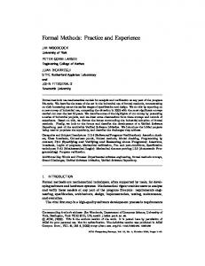
5.1.3 Safety objective Allocation Principle For a WCU (Wayside Control Unit), the safety objective is 10-9/h (maximum unsafe situation rate). The WCU objective has to be decomposed into objectives for equipments, boards, and finally components. An example of decomposition of objective is represented by the following figure:
23
WCU 10-9/h
WCU B 5.10-10/h
WCU A 5.10-10/h
hardware 4.10-10/h
software 10-10/h
boards 3,9.10-10/h
cardfiles 10-11/h
The allocation for all cardfiles is 10-11/h, i.e. allocation for each one of the 2 cardfiles is 5.10-12/h. The allocation for all boards is 3.9 .10-10/h, the allocation for each one of the 23 board is 1.65 .10-11/h.
5.1.4 Safety properties Allocation Principle A Fault Tree Analysis (FTA) is performed to decompose system hazards into equipment hazard. Each equipment hazard is allocated to a unique equipment.
5.1.5 Safety definition for an equipment An equipment is safe if the probability of all equipment hazards allocated to this equipment is below the safety objective of the equipment. If there is no equipment hazard allocated to an equipment, the equipment is not safety related, and no safety activities are required for this equipment.
5.1.6 Reliability validation (HW) For each board, an analysis (FTA and/or FMEA) is performed to list all failures or combination of failures that could lead to an unsafe behaviour of the board. It leads to individual component failure or combination of individual component failure. Thanks to the reliability data handbook, it is possible to know the reliability of each component, and therefore estimate the probability of a behaviour of the board, and then compare it with the safety objective to determine if the objectives are met.
24
5.1.7 Reliability validation (SW) The development/validation process guarantees that the source code (B model) is safe. The source code unsafe behaviour probability is zero. The execution of the software may lead to wrong results even without hardware failure (electromagnetic fields, for instance). An analysis of the Vital Coded Processor gives a probability of 10-10/h for this hazard.
5.2 Use of probability within event-B models In this section, we are making a proposal for an approach to the modelling of probability classes in event-B models suitable for the purposes of the STS pilot study.
5.2.1 Probability A global variable P is defined in the model. This variable is initialized at zero, and is decremented by the events.
5.2.2 Properties All properties are associated with an acceptable probability of violation of the property, corresponding to a Safety Integrity Level (SIL).
SIL
probability of violation of the property (examples)
property category
0
1
0
1
10-3/h
-3
2
10-5/h
-5
3
10-7/h
-7
4
10-10/h
-10
For instance, a property "Prop" associated to SIL2 will be modelled in event B as : Invariant Inv1 : Prop or (P10-4/h
0
Probable
10-6/h< Occurrence < 10-4/h
-4
Occasional
10-8/h < Occurrence < 10-6/h
-6
Remote
10-9/h < Occurrence < 10-8/h
-8
Improbable
Occurrence < 10-9/h
-9
Example of event associated to category "Remote”: Event xxx Guard1 : yyy Action1 : P=P-8 Action2 : zzz … In fact, most events are in the "frequent" category, the other categories are for degraded mode, failures, emergency procedures, etc.
5.2.4 Combination of failures Usually, a single failure is not enough to cause an unsafe situation. The typical case is one or several failure(s) causing a degraded mode, and in this degraded mode, another failure can lead to an unsafe situation. This is an example of modelization :
26
Invariant1 : Safe=TRUE or P P