In these studies, the authors utilize kirigami, a variation of origami that relies on cuts in the fold patterns before the structure becomes volumetric. Other methods.
COVER SHEET
Paper Number: 271 Title: Deployable Structures Constructed from Composite Origami Authors: James O’Neil Antonio Alessandro Deleo Hiromi Yasuda Marco Salviato Jinkyu Yang
ABSTRACT The goal of this paper is to construct lightweight, deployable, yet stiff structures made from composite origami. In particular, the deployable origami structures manufactured in this study are based on the Tachi-Miura-Polyhedron (TMP). The TMP is a bellows-like structure that can be stored in a flat state and deployed to a finite volume with defined axial stiffness. The stiffness is highly tunable and depends on several geometric properties as well as the material properties of the crease-lines. The structure can exhibit auxetic behavior among other interesting traits when tuned properly. This study will focus on the manufacturing of this origami utilizing composite materials which can offer a lower weight and higher stiffness solution for constructing the TMP for real world engineering applications. Prototypes are constructed with dry glass fibers to form the crease-lines. Polyurethane resin is then infused to bond the structure together and protect the resin. This research can contribute to the design of origami-based deployable structures in industry and research. The manufacturing process used is relatively simple since it does not require a complex system of moving parts or mechanical connections. Additionally, this structure is hollow and therefore offers a space filling feature which gives it great potential as a space structure or a disaster relief shelter.
INTRODUCTION Paper is a cheap and simple material to work with and is widely used to study origami structures. However, it is not an effective material choice for engineering applications. Instead, engineers must look to other materials that can provide stiff _____________ James O’Neil, University of Washington, 3940 Benton Lane NE, Seattle, WA 98195-24001. Antonio Alessandro Deleo1 Hiromi Yasuda1 Marco Salviato1 Jinkyu Yang1
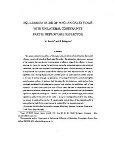
yet foldable structures. This paper will introduce a novel manufacturing method to construct origami structures through the use of composite materials. These materials offer engineers the ability to develop deployable structures that save weight and volume and are highly tunable through their geometry and their materials properties. Deployable structures already made from origami prototypes include but are not necessarily limited to solar panels and sails [1], emergency shelters, and bridges [2]. These characteristics are also important in space and flight applications. The proposed origami structures can also reduce complexity in mechanical systems as they do not require mechanical joints and hinges. Origami structures can see an application as impact mitigation and as the chassis of robotic systems in addition to the aforementioned applications due to their flexible and tunable stiffness configurations [3]. There are not many manufacturing methods for composite origami found in previously published work. Those that have been introduced generally focus on the adaptation of composite origami for sandwich core or honeycomb core applications [4, 5]. In these studies, the authors utilize kirigami, a variation of origami that relies on cuts in the fold patterns before the structure becomes volumetric. Other methods introduce the ability to control the curvature of facets and obtain self-folding behavior through a combination of active and passive core materials [6]. These methods allow one to maintain foldability of the structure either during manufacturing and/or after manufacturing. One method fabricates the origami utilizing molds and do not introduce slits or different material in the crease-lines. The resulting product is rigid and it was shown that this may be useful for improving compression stiffness and impact response [7]. Although insightful for their respective applications, these manufacturing methods cannot be applied to deployable structures. Work conducted in North Carolina State University has developed deployable CubeSat booms and other origami folds using a technique that involves resin infusion for both the facets and crease-lines [8]. This method can be used to tailor the behavior of the creaselines but only by varying the resin that is infused as the crease-lines maintain the same material and ply orientation of the facets. This paper will validate the importance of this novel manufacturing method by successfully demonstrating the fabrication of the Miura-ori fold pattern and the Tachi-Miura Polyhedron (TMP). TMP is a bellows-like structure that folds from a flat state into a finite volume and is a strong candidate to act as a deployable structure. An example of TMP is shown in Figure 1. Miura-ori is known as rigid origami which means that it does not exhibit significant bending or stretching in its facets. As TMP is a derivation of the Miura-ori fold, it also exhibits rigid-folding behavior among other interesting qualities such as negative stiffness, strain hardening near the end of compression, and negative Poisson’s ratio [9]. Minimum success for this study is achieved when a TMP produced from our manufacturing process exhibits near rigidfoldability and is deployable.
Figure 1. An isometric view of a generic TMP structure as it is folded from left to right.
Tachi-Miura Polyhedron Geometry and Behavior TMP is a partial derivation of the Miura-ori fold pattern as can be seen in Figure 2a below. Just like the Miura-ori fold, TMP is also rigid foldable.
Figure 2a. A TMP fold pattern where dashed lines indicate valley folds and solid lines represent mountain folds. Notice the presence of the Miura-ori unit cell. 2b. A partially folded Miura-ori unit cell with important geometrical parameters. 2c. Geometrical properties required to define a layer of TMP. 2d. A side-view of TMP with the fold angle marked and the total height H labeled. [9]
As shown above, a Miura-ori unit cell has three valley folds and one mountain fold. In the center is a sharp vertex. Four geometrical parameters are introduced in Figure 2b as well. These are the panel tilt angle α, half of the dihedral main-crease fold angle θM, half of the dihedral sub-crease fold angle θS, and the angle θG. Eq. 1 and 2 give the relationships between these angles as [10]: tan(𝜃𝐺 ) = tan(𝛼) sin(𝜃𝑀 )
(1)
sin(𝜃𝐺 ) = sin(𝛼) sin(𝜃𝑆 )
(2)
One can control the folding behavior of the TMP through these relationships by modifying only two parameters. Figure 2b is a TMP folding pattern with Miura-ori highlighted. This demonstrates how the Miura-ori unit cell fits into the TMP’s geometry. It can immediately be seen from the fold pattern of the TMP that there are other geometric parameters that are needed to fully define the structure. Figures 2c and 2d indicate the other parameters that are needed. The other parameters are layer height d, parallelogram width m, and trapezoid half-width l. In addition to θM , these variables are the only five parameters needed to describe the state of the structure. Eq. 3 allows us to relate the major crease-line angle with the height of the TMP: 𝐻
cos(𝜃𝑀 ) = 𝑁𝑑
(3)
N is the number of layers in a TMP structure. Through this equation, it is possible to determine the folded state of the TMP. However, to provide better comparison between force-displacement and stiffness properties of different TMP structures, a fold angle ratio is generally used instead. We define this ratio as: 𝜃
𝛾 = 90°
(4)
Figure 3 defines the “breadth” (B) and “width” (W) of the TMP. These dimensions are needed to derive a Poisson’s ratio for the TMP. Also shown is the cross-sectional area A.
Figure 3. The breadth B and width W of the TMP while it is undergoing folding. A is the crosssectional area of the TMP.
There are two Poisson’s ratios that can be derived with TMP. They are given below in Equations 5 and 6. 𝜈𝐻𝐵 =
4𝑚 tan(𝛼)𝑐𝑜𝑠(2𝜃𝐺 )𝑐𝑜𝑠2 (𝜃𝐺 )+𝑑 cos(𝜃𝑀 )cot(𝜃𝑀 ) 2𝑚𝑠𝑖𝑛(2𝜃𝐺 )+𝑑𝑠𝑖𝑛(𝜃𝑀 )
𝜈𝐻𝑊 = −
4𝑚 tan(𝛼)𝑠𝑖𝑛(2𝜃𝐺 )𝑐𝑜𝑠2 (𝜃𝐺 ) 2𝑚𝑐𝑜𝑠(2𝜃𝐺 )+
𝑑 +2𝑙 tan(𝛼)
cos(𝜃𝑀 )cot(𝜃𝑀 )
(5) (6)
In Eq. 5, it is clear that the Poisson’s ratio in the HB (height-breadth) direction will be positive through the entire compression of most configurations. However, form Eq. 6, it is evident that the Poisson’s ratio is always negative, regardless of the geometric inputs. Theoretically, this means that the TMP’s width should always decrease as the structure is compressed. Figure 4a demonstrates what the TMP width will look like under a full compression. The slope should be negative if a negative Poisson’s ratio is adhered to. Figure 4b demonstrates the normalized volumetric change of the TMP during full compression.
Figure 4a. The normalized change in width as a TMP with d = l = m = 40 mm and α = 45° is fully compressed. 4b. The normalized change in area as the same TMP is fully compressed.
From Figure 4b, the volume increases and then peaks before the structure is folded 50% of its full height. For our composite prototypes, we will want to see the TMP deploy from a fold angle ratio of 1, up to around the peaking region of the volumetric curve. In a real life application, if a deployable structure is needed as an emergency shelter or other storage, controlling the TMP and having it achieve this volumetric state may be very desirable. MANUFACTURING Traditional composite manufacturing methods frequently require the use of autoclaves and advanced vacuum systems such as VARTM (Vacuum Assisted Resin Transfer Molding). To overcome these extra costs and complexity, another similar, yet cheaper and as reliable method was used: VBO (Vacuum Bag Only). In this method, the fibers instead of being dry are already pre-impregnated with resin; therefore, the vacuum is only used to supply pressure and not to allow the resin to flow through the fibers. The curing cycle choice is also very flexible. Depending on the type of resin used, some cycles can be cured at ambient temperature for a longer period of time, or cured in a ventilated oven at a higher temperature which considerably reduces the curing time. In this experiment, the facets of the TMP structure were made out of weave T700 CFRP cut using an automated fabric cutter and cured using a traditional hot-press method. The crests were manufactured using fiberglass impregnated with Sharkthane Flex Pro 30-20 urethane epoxy and joined to the facets using the VBO method. The urethane epoxy was cured overnight at ambient temperature. Figure 5 below shows the schematic of a VBO technique.
Figure 5a. Schematic of VBO technique. 5b. Example of a specimen during curing. [9]
Different layups and materials have been used and tested by the authors and it was found that using the crest of the origami tructure as integrant part of the layup was the most efficient in terms of manufacturability and folding repeatability [9]. The whole laminate after manufacturing consisted of three plies except when a crest is wanted, so in that case the carbon plies would be discontinued and only the crest ply made out of fiberglass would be present, as shown below in Figure 6. The steps used to manufacture a 3-layer TMP structure are shown below in Figure 7. The pre-cured CFRP facets are laid down on a garolite plate covered of release agent following the chosen geometrical parameters. Subsequently, bagging materials are prepared and put on the side. The urethane epoxy is mixed and spread over the single fiberglass layer and the last layer of the CFRP facets are laid down exactly on top of the lower ones and everything is properly aligned before the Teflon and vacuum bag are used.
Figure 6. Schematic of the laminate for the TMP Origami Structure using CFRP (Carbon Fiber Reinforced Plastic) and GF (Glass Fiber) impregnated with a urethane resin. [9]
Figure 7a. First layer of CFRP facets are laid down following geometrical properties. 7b. The garolite plate is prepared for the VBO technique. 7c. The laminate is let cured overnight under vacuum pressure to ensure material adhesion. 7d. The final laminate after cure and de-bagging.
EXPERIMENTS An experiment was conducted to verify that the manufacturing process produced TMPs that exhibited the expected kinematic behavior. A three layer composite TMP prototype was compressed to varying heights. We started the compression in the flat stage and ended in its folded stage as shown in Figure 8a below. At each height, the width W was measured with measurements being taken between the vertices labeled in Figure 8b. The main-crease line fold angle was also calculated from images of the side of the TMP. Figure 8c plots the analytical or predicted width of the TMP along with the measured data.
Figure 8a. The various stages a TMP with d = l = m = 40 mm, α = 45°, and N = 3 is compressed (flat to folded stages) for experimental verification. 8b. The height H and width W of the TMP at a given stage. 8c. Experimental results of the width change as the TMP is compressed.
The experimental results show good agreement with the analytical behavior and therefore verifies that the manufactured TMP prototypes follow the kinematics laid out in our theory. Deviations occur in minor manufacturing defects such as small misalignments in the panels. Additionally, the theory assumes that the crease-lines have no gap and so there is no curvature between the facets. These gaps may vary in size and could cause unwanted deformation along the crease-lines further deviating the results from theory. These defects are minor and will improve as the manufacturing process is optimized. Finally, the deployability of the structure was tested with a simple compress-andrelease test of the same TMP prototype. The prototype is weighed down and compressed using a 0.5 mm acrylic plate. Cables are fed through the plate at two opposite edges and are used to hold the structure in place. Then the cables are released and the structure is deployed. Figure 9 presents the results of the deployment test.
Figure 9. From left to right, results of the deployment test of the TMP prototype.
As we can see, over a 200 ms timeframe, the TMP is capable of expanding its volume significantly. The weight of the plate also keeps the TMP from deploying back to its flat-folded state. This means that we can maintain control over its deployability. The mechanisms which drive the process can be more elaborate. If we compare the rightmost image of Figure 9 with the peak TMP structure in Figure 4b, we can see that we did indeed achieve a large volumetric expansion near the peak volume. CONCLUSIONS The objective of this paper was to verify through both qualitative inspection and basic kinematic experimentation that origami structures, more specifically rigid origami structures such as the Tachi-Miura Polyhedron (TMP), could be manufactured using composite materials for a wide range of engineering applications. Such applications include deployable structures, impact mitigators, and so much more in space and flight where robust structures with high strength-toweight would be beneficial. Our goal was to construct a composite TMP. This was achieved by fabricating the facets with carbon-fiber prepreg and using glass fibers that were infused with a polyurethane matrix to form the crease-lines. Vacuum-bag-only methods (VBO) were utilized to cure and consolidate the unfolded structure. Our process is cheap, efficient, and not overly time consuming. Conducted experiments showed that the constructed composite TMPs respond in compression as expected based on previously studied kinematics and are deployable. Future investigations will involve gathering data on the force-displacement behavior of the composite TMP structures. TMP is normally studied assuming all of the crease-lines have the same torsional spring constant. However, due to the nature of our layup where the glass fibers are not oriented the same along the main creaselines as they are along the sub crease-lines, a new model will need to be developed to account for varying torsional spring constants. In addition, as we mature the manufacturing process, we will work towards fabrication of origami structures that do not follow a rigid assumption. Achieving this goal would verify the robustness of this manufacturing process for composite origami structures.
REFERENCES 1.
Tsuda, Y., Mori, O., Sawada, H. Yamamoto, T., Saiki, T., Endo, T., and Kawaguchi, J. 2011. “Flight Status of IKAROS Deep Space Solar Sail Demonstrator.” Acta Astronautica, 69: 833840. 2. Reis, P., Jiménez, F., and Marthelot, J. “Transforming architectures inspired by origami.” Proceedings of the National Academy of Sciences of the United States of America, 120(40): 12234-12235. 3. Miyashita, S., Guitron, S., Ludersdorfer, M., Sung, C.R., and Rus, D. “An untethered miniature origami robot that self-folds, walks, swims, and degrades.” Computer Science and Artificial Intelligence Laboratory, MIT, Cambridge, MA. 4. Saito, K., Pellegrino, S., and Nojima, T. 2014. “Manufacture of Arbitrary Cross-Section Composite Honeycomb Cores Based on Origami Techniques.” Journal of Mechanical Design, 136: 051011-1 – 051011-9. 5. Saito, K., Fabio, A., and Scarpa, F. 2011. “A Cellular Kirigami Morphing Wingbox Concept.” Journal of Intelligent Material Systems and Structures, 22: 935-944. 6. Chillara, V., Headings, L., and Dapino, M. 2015. “Self-Folding Laminated Composites For Smart Origami Structures.” Proceedings of the ASME 2015 Conference on Smart Materials, Adaptive Structures and Intelligent Systems. 7. Kshad, M., D’Hondt, C., and Naguib, H. 2017. “Carbon nano fibers reinforced composites origami inspired mechanical metamaterials with passive and active properties.” Smart Materials and Structures, 26: 105039. 8. White. C. 2016. “Manufacturing and Structural Characterization of Flexible and Dual-Matrix Deployable Composites for Space Application.” North Carolina State University Thesis. 9. Deleo, A., O’Neil, J., Yasuda, H., Yang, J., and Salviato, M. 2018. “Composite Origami: Foldable Structures Based on Tachi-Miura-Polyhedron Origami Technique.” Proceedings of SAMPE 2018. 10. Yasuda, H., Yang, J. 2015. “Reentrant Origami-Based Metamaterials with Negative Poisson’s Ratio and Bistability.” Physical Review Letters, 114: 185502-1 – 185502-5.