Vol. 25, No. 5 | 6 Mar 2017 | OPTICS EXPRESS 5341
Depth detection in interactive projection system based on one-shot black-and-white stripe pattern QIAN ZHOU,1,5 XIAORUI QIAO,2,5 KAI NI,1,3 XINGHUI LI,1,4 AND XIAOHAO WANG,1 1
Division of Advanced Manufacturing, Graduate School at Shenzhen, Tsinghua University, Shenzhen 518055, China 2 Department of Precision Engineering, The University of Tokyo, 7-3-1, Hongo, Bunkyo-ku, Tokyo,Japan 3
[email protected] 4
[email protected] 5 These authors contributed equally to this work
Abstract: A novel method enabling estimation of not only the screen surface as the conventional one, but the depth information from two-dimensional coordinates in an interactive projection system was proposed in this research. In this method, a one-shot black-and-white stripe pattern from a projector is projected on a screen plane, where the deformed pattern is captured by a charge-coupled device camera. An algorithm based on object/shadow simultaneous detection is proposed for fulfillment of the correspondence. The depth information of the object is then calculated using the triangulation principle. This technology provides a more direct feeling of virtual interaction in three dimensions without using auxiliary equipment or a special screen as interaction proxies. Simulation and experiments are carried out and the results verified the effectiveness of this method in depth detection. © 2017 Optical Society of America OCIS codes: (120.0120) Instrumentation, measurement, and metrology; (330.1880) Detection; (100.4995) Pattern recognition, metrics; (330.5000) Vision - patterns and recognition.
References and links 1.
K. D. D. Willis, “Pre-history of handheld projector-based interaction,” Pers. Ubiquitous Comput. 16(1), 5–15 (2012). 2. K. Ni, Q. Zhou, L. Chen, P. Sun, H. Xu, Y. Gao, J. Ma, Y. Li, and M. Liu, “A location system based on two-dimensional position sensitive detector used in interactive projection systems,” Proc. SPIE 7850, 78502G (2010). 3. X. Qiao, Q. Zhou, K. Ni, L. He, G. Wu, L. Mao, X. Cheng, and J. Ma, “Real-time interactive projection system based on infrared structured-light method,” Proc. SPIE 8558, 855802 (2012). 4. P. Beardsley, J. van Baar, R. Raskar, and C. Forlines, “Interaction using a handheld projector,” IEEE Comput. Graph. Appl. 25(1), 39–43 (2005). 5. Q. Zhou, K. Ni, Y. Lu, L. Chen, Y. Gao, L. He, H. Guo, J. Ma, Y. Li, and M. Liu, “Indirect measurement of the infrared pen point used in a short throw interactive projection system,” Proc. SPIE 7850, 78502F (2010). 6. A. D. Wilson, “Play anywhere: a compact interactive tabletop projection-vision system,” in Proc. of the 18th Annual ACM Symposium on User Interface Software and Technology (2005), pp. 83–92. 7. J. Letessier and F. Berard, “Visual tracking of bare fingers for interactive surfaces,” in Proc. of the 17th Annual ACM Symposium on User Interface Software and Technology (2004), pp. 199. 8. C. Tomasi, A. Rafii, and I. Torunoglu, “Full-size projection keyboard for handheld devices,” Commun. ACM 46(7), 70–75 (2003). 9. G. Tovi and W. Daniel, “Going deeper: a taxonomy of 3D on the tabletop,” in 2nd Annual IEEE International Workshop on Horizontal Interactive Human-Computed Systems (2007), pp. 137–144. 10. I. Shahram, H. Steve, T. Stuart, D. Rosenfeld, N. Villar, A. Butler, and J. Westhues, “Going beyond the display: a surface technology with an electronically switchable diffuser,” in 21st Annual ACM Symposium on User Interface Software and Technology (2008), pp. 269–278. 11. K. Yasuaki and N. Takeshi, “Tablescape plus: interactive small-sized vertical displays on a horizontal tabletop display,” in 2nd Annual IEEE International Workshop on Horizontal Interactive Human-Computed Systems (2007), pp. 155–162. 12. C. R. Wren and Y. A. Ivanov, “Volumetric operations with surface margins,” in Computer Vision and Pattern Recognition: Technical Sketches (2001).
#282175 Journal © 2017
https://doi.org/10.1364/OE.25.005341 Received 5 Dec 2016; revised 14 Feb 2017; accepted 14 Feb 2017; published 28 Feb 2017
Vol. 25, No. 5 | 6 Mar 2017 | OPTICS EXPRESS 5342
13. P. Su, R. E. Parks, L. Wang, R. P. Angel, and J. H. Burge, “Software configurable optical test system: a computerized reverse Hartmann test,” Appl. Opt. 49(23), 4404–4412 (2010). 14. Y. Wang, S. Negahdaripour, and M. D. Aykin, “Calibration and 3D reconstruction of underwater objects with non-single-view projection model by structured light stereo imaging,” Appl. Opt. 55(24), 6564–6575 (2016). 15. P. S. Huang and S. Zhang, “Fast three-step phase-shifting algorithm,” Appl. Opt. 45(21), 5086–5091 (2006). 16. Q. Zhang and X. Su, “High-speed optical measurement for the drumhead vibration,” Opt. Express 13(8), 3110– 3116 (2005). 17. S. Zhang, “Recent progresses on real-time 3D shape measurement using digital fringe projection techniques,” Opt. Lasers Eng. 48(2), 149–158 (2010). 18. Y. Wang and S. Zhang, “Optimal fringe angle selection for digital fringe projection technique,” Appl. Opt. 52(29), 7094–7098 (2013). 19. H. Kawasaki, R. Furukawa, R. Sagawa, and Y. Yagi, “Dynamic scene shape reconstruction using a single structured light pattern,” in IEEE Computer Vis. Pattern Recognition (2008), pp. 1–8. 20. W. Lohry, V. Chen, and S. Zhang, “Absolute three-dimensional shape measurement using coded fringe patterns without phase unwrapping or projector calibration,” Opt. Express 22(2), 1287–1301 (2014). 21. S. Zhang and P. Huang, “High-resolution, real-time 3D shape acquisition,” in Computer Society Conference on Computer Vision and Pattern Recognition Workshops (2004), pp. 28–38. 22. P. S. Huang, C. P. Zhang, and F. P. Chiang, “High-speed 3-D shape measurement based on digital fringe projection,” Opt. Eng. 42(1), 163–168 (2003). 23. O. Hilliges, S. Izadi, and A. D. Wilson, “Interactions in the air: adding further depth to interactive tabletops,” in Proc. of the 22nd Annual ACM Symposium on User Interface Software and Technology (2009), pp. 139–148.
1. Introduction An interactive projection system allows people to create and sends powerful messages by simply touching the screen. A typical interactive projection system generally consists of a projection device, a location subsystem, and a signal processing unit. The key component among these is the location subsystem [1–4], as it determines the characteristics of the interactive system and the performance of interactive experiences. Location subsystems of currently available interactive projection technologies mainly involve three types, an interactive whiteboard, handing-device-type subsystem, and computer-vision-type subsystem [3]. The first two types depend on the location sensors. Interactions occur when the finger or the interactive proxy touches the screen. The touch positions can be sensed by the sensors of the screen and the proxy [2–5], which results in confinement of the interactions on the screen or in inconvenient interactions due to the handing device. The interactive instrument and the special screen equipped with sensors play an important role in promoting the location function of the system. Therefore, the resulting interaction is unnatural and awkward, since users have to be instrumented, and both the installation and the physical movement of the screen are inconvenient. In those systems equipped with the first two types of location subsystems, the effectiveness and the accuracy of the estimation of the two-dimensional (2D) screen coordinates are considered important, but the estimation of depth information, which will benefit many applications have not been considered. Compared with abovementioned two types, the third type that is based on the combination of projection techniques for display and computer vision techniques for sensing affords flexibility in sensing various objects placed on the surface [6]. The interactive surface in this case is a typical technology for supporting natural interactions [7], such as finger or hand gestures. This technology has made much more progress, helping users to get rid of auxiliary instruments and make interactions possible just by hand [8]. Despite these advantageous aspects, the interactions with such interactive surfaces are also bound to the display surfaces. This makes some real-world actions such as stacking objects or placing them in containers difficult and non-intuitive. For meeting the great demand on 3D natural interactions, a great deal of researches have been focused on depth information acquisition [9]. One way to utilize the space above the screen is to use 3D input devices, such as data gloves or styluses with markers; however, the working style of such devices is awkward and unnatural. Camera-based technology can sense the 3D positions and detect gestures by using a depth-sensing or stereo camera to build a depth map for estimating the distance of an object with respect to the screen, but it suffers from some
Vol. 25, No. 5 | 6 Mar 2017 | OPTICS EXPRESS 5343
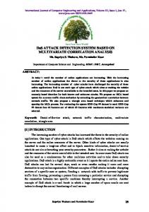
robustness problems. Improvement of the robustness always required special projection screens, such as switchable diffusers or holographic materials, to support the sensing of the display [10, 11]. Depth detection can also be achieved by using two cameras and performing stereo calculations [12]. But in such case, the correspondence problem becomes significant because the correspondence errors will reduce the accuracy of the 3D reconstruction results. Structured light is widely used in optical field to achieve precise 3D measurement for large, highly aspherical shapes and achieve accurate results [13]. Therefore, structured light is possible to be used to interactive system to improve the accuracy of the 3D measurement. Thus structured light [14–19], especially one-shot pattern one that is represented as the marker has been widely used to reduce the correspondence errors and improve the accuracy of the 3D information, such as 3D facial expressions and hand gestures, however, this method suffers from the drawbacks of its complicated code, slow processing of the pattern and slow measurement, which may cause the failure of the tracking of the hand movement. Hence, an effective method for detecting depth information is essential for an interactive projection system. This paper then proposes a simple yet effective depth detection method with utilization of a one-shot black-and-white stripe pattern. Differing from the conventional complicated use of these stripe patterns for 3D reconstruction by extraction and unwrapping of their phases [20], or for measurement of slow movement by using the shift of their phases [21, 22]. In our system, the stripe pattern is only a black and white one and no any phase information required. Since there is no need to consider the robustness of the phases, the segmentation and recognition of this stripe pattern are greatly simplified, enabling a rapid detection. In order to achieve natural 3D interactions, an important issue is to acquire the depth information. In Ref [23], a virtual reality tabletop system was proposed, in which the depth information is mainly acquired by the 3DV ZSense camera and the shadow provided additional depth feedback for strengthening the coupling the action between hand and virtual objects. Although the shadow was used in this system, the main role of it was to improve the awareness of the virtual reality system. In our method, differing from that shown in [23], the shadow is used for correspondence features to get the 3D position. The accurate depth information acquisition was built by using the precise geometric relationship between the hand and its shadow on the screen in the interactive projection system. The correspondence method was illustrated, built and simulated. Experiments were conducted to verify the accuracy of our proposed depth acquisition method. 2. Principle As mentioned above, an interactive projection system is composed of a projector, a camera, and a computer. The stripe pattern is projected on a planar surface. When a hand or an object appears in the projection area, the pattern deforms due to the modulation of the height of the hand or the object. Then, the camera captures the deformed image and transmits it to the computer in real time. The frame is processed by our novel algorithm, and depth information can be acquired during the interaction. Basic principle of depth detection in our interactive projection system is triangulation method [18], as shown in Fig. 1. In this figure, point D represents the depth information of the fingertip, and Dcp is the distance between the optical center of the projector and the camera, which is called baseline, which is parallel to the projection screen. Dcs is the standoff distance from the baseline to the screen. Light passes through point D and is captured by the camera. Point C represents the projection result of point D. When the hand appears in the projection area, it occludes the light. Point A represents the image of point D. In our system, the Z-axis represents the depth direction. Hence, in the system, EDB ∽ADC. Further, the depth of point D can be obtained as follows:
Vol. 25, No. 5 | 6 Mar 2017 | OPTICS EXPRESS 5344
L × Dcs Dcp + L
(1)
lpp × m × Dcs Dcp + lpp × m
(2)
hD =
Equation (1) can be rewritten as follows: hD =
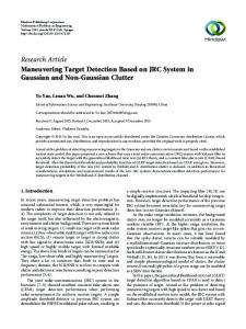
where lpp is the length per pixel and m is the pixel distance from A to C [3]. The determination of L is the key task in obtaining the height of D, which suggests the correspondence between the point in the projected pattern and that in the deformed pattern. Note that the hand is always accompanied by its shadow in the projection system. The light passing through the fingertip is just at the top of the shadow. As shown in Fig. 2, the fingertip position matches the top of its shadow. In the captured image, we need to position the first stripe on the finger and the first stripe on the shadow. These two stripes are the same as those before the hand appears in the scene. Hence, the correspondence can be obtained by just a single pattern and coding the pattern is not necessary. This simple and effective correspondence method is implemented in our system.
Fig. 1. Principle of depth detection system.
Fig. 2. Correspondence of stripe pattern.
Vol. 25, No. 5 | 6 Mar 2017 | OPTICS EXPRESS 5345
To obtain the depth of point D, the positions of point A and C in the captured images must first be known. The stripe pattern is generated by our pattern generating programming. According to the screen size, the pattern image can be generated automatically by our programming. Here the width of the stripe is set the same width and the pattern image is the same size as the screen size. Let w denote the width of the stripe; l(i), the white connected domain in the image, where 1 ≤ i ≤ M (M being the total number of white connected domains); and C(i), the center of each white domain. Then, I = C (i + 1) − C (i ) ≤ w si ( x, y ) =
b1i ( x, y ) + b 2i ( x, y ) + u1i +1 ( x, y ) + u 2i +1 ( x, y ) 4
(3) (4)
i = min(I) is the first white domain that is segmented by the shadow, as shown in Fig. 3. The edge points of b1i (x,y), b2i (x,y), u1i + 1 (x,y), u2i + 1 (x,y) are found. Therefore, the top of the shadow, si (x,y), i.e., point C, is obtained according to Eq. (4).
Fig. 3. Method for estimating the shadow and fingertip.
The next step, aimed at obtaining the depth of the fingertip, is to determine the 2D coordinates of the fingertip. Two scenarios are possible with regard to the 2D coordinates of the fingertip. The first scenario is that the accurate fingertip location has been obtained by other methods, such as the use of infrared sensors and color markers. In such scenario, the depth information is always missing, whereas the 2D information is accurate. Therefore, our method can be recognized as being a method for overcoming the drawbacks. The second scenario is that the location of the fingertip is unknown. In such a case, the fingertip domain can be found by line searching. The position of the fingertip projection on screen is the center of ln (x,y), which is the same as point A. The height of point D or the depth of the fingertip is obtained from Eq. (2). In this way, the depth information can be obtained by just one frame; hence, this is a rapid and efficient approach. 3. Experiments and results First of all, the correspondence method is simulated. The scene in the simulation is constructed by 3Ds MAX 2009. The projection pattern is a black-and-white stripe, and the fingertip is measured, as shown in Fig. 4. The screen size in the simulation is 640 mm × 480 mm, and the captured image is 640 × 480 pixels. This implies that 1 mm represents 1 pixel on the screen. Dcs is 711 mm, Dcp is 350 mm, and w is 3 pixels (3 mm). All the parameters are precise in the simulation.
Vol. 25, No. 5 | 6 Mar 2017 | OPTICS EXPRESS 5346
We choose nine points on the screen as our measurement points, each of which has five heights to be verified, as shown in Figs. 4 and 5. It should be noted that the points cannot be very close to the edge of the screen, because the detection of the shadow may fail when it is outside of the range of the scene. We assume that the 2D positions of the fingertip are already known and that the depth information of each point is measured by our algorithm. The distance to the screen varies from 60 to 20 mm. The distances are measured every 10 mm, as shown in Fig. 4. Figure 6 illustrated the verification results. Here, the blue lines represent the real data, and the color squares represent the simulated data. It is seen that all the simulated data are distributed closely around the actual data, and the error is less than 3 mm, which demonstrates the effectiveness of our proposed method. This also suggests that the depth information of the fingertip can be detected accurately during interaction. The accuracy of the distance which close to the screen implies that the action of touching the screen will also receive a good response.
Fig. 4. Five different heights at a point in simulation.
Fig. 5. Selected nine measurement points on the screen.
Vol. 25, No. 5 | 6 Mar 2017 | OPTICS EXPRESS 5347
Fig. 6. Heights measured at the nine points.
After simulations, an experimental platform is set up to verify the accuracy of the proposed method in a real scene, as shown in Fig. 7. The black-and-white stripe is projected on a white wall. The experimental platform consists of a projector, a monochrome charge-coupled device camera with an image capture card (OK_M10B), and a personal computer. The resolution of the projector is 854 × 480 pixels, and that of the camera is 640 × 480 pixels. Dcp is 388 mm, Dcs is 1037 mm, and w is 4 pixels (3.5 mm). The system was previously calibrated before the measurement.
Fig. 7. Experimental platform.
In the experiment, a paper rod is used as an interaction object in the system because measurement with it is simple, as shown in Fig. 8. The distance between the touch point on the screen and the interactive point D is 22 mm, that is, the depth is 22 mm. We use this rod to touch the screen, so the depth remains 22 mm. In fact, in the error analysis part, we use the knowledge that the shorter the distance, the greater will be the error introduced. Therefore, if the depth of 22 mm is accurate, a longer distance will be more accurate.
Vol. 25, No. 5 | 6 Mar 2017 | OPTICS EXPRESS 5348
Fig. 8. Design sketch of interaction using paper rod.
First, we select 32 points on the screen, as shown in Fig. 9. The red circles represent the measurement points. All these points are previously marked by pencil, and we use the paper rod to touch them on the screen. As shown in Fig. 10, all the experimental data are distributed close to the actual data, and the maximum error is 4 mm, which is acceptable for interaction with the hand or a rod in an interactive projection system. This means that the depth information can be obtained accurately in a real scene.
Fig. 9. 32 points to be measured.
Fig. 10. Depth information at 32 points.
Vol. 25, No. 5 | 6 Mar 2017 | OPTICS EXPRESS 5349
To verify the randomness and accuracy of the depth detection in the system, the paper rod is made to traverse through the screen, and 600 random points are measured in total, as shown in Fig. 11. Only one point is off the actual data; the rest are close to the actual data, which implies fewer errors during the interaction. The depth detection is unaffected by whether the points are located at the edge of the screen or in the center region. For further demonstration of the performances of this method, experiment is conducted for depth detection in natural interactions, as shown in Fig. 12. The depth of an interactive point is estimated in real time during the hand writing. Steps a, c, e, and f are the intervals between the two actions of touch drawing, and the estimated depth is higher than the set value, 22 mm. Therefore, no output is obtained. Steps b, d, and g are the periods of touch drawing, and the estimated depth is smaller than the set value of 22 mm; therefore, an output is obtained. In this way, the depth of the interactive point is successfully detected during natural drawing. According to Eq. (2), the depth error is caused mainly by the pixel number m due to the width of stripe on the finger and the shadow of the fingertip. The uncertainty of the height, Δh, can be expressed using the uncertainty of the pixel number, Δm, according to Eq. (5). In the experiment, the stripe width is 4 pixels, i.e., about 3.5 mm.
Fig. 11. Depth information at 600 random points.
Vol. 25, No. 5 | 6 Mar 2017 | OPTICS EXPRESS 5350
Fig. 12. Depth detection during writing by hand.
Δh =
lpp × Dcs × Δm m × (m + Δm) × lpp 2 Dcp + ( 2m + Δm ) + Dcp
(5)
It is noticeable that the depth accuracy is affected by both the uncertainty of the pixel number (Δm) and the height (h) itself. With an increase in Δm, which is caused mainly by image processing, the height error increases. As the height increases while the Δm remains unchanged, the ratio of uncertainty decreases, and thereby the height error decreases, as shown in Fig. 13. This is also the reason why we perform measurement only at a distance close to the screen. The errors at a height of 22 mm are represented by the green squares in the figure. We can see that when Δm is 3 pixels, the error at a height of 22 mm is about 5.4 mm, which agrees with the errors in the experiment. Further, on the basis of the accurate output of touch drawing in Fig. 12, the error is found to be acceptable. The error depends mainly on the width of the stripe. As shown in Fig. 13, if the width of the stripe is more refined, Δm is 1 pixel and the depth error is less than 2 mm at a height of 22 mm. Hence, a refined stripe pattern and a high resolution camera would be useful in improving the accuracy of the system.
Vol. 25, No. 5 | 6 Mar 2017 | OPTICS EXPRESS 5351
Fig. 13. Error at a height of 22 mm.
4. Conclusions This paper proposes a depth detection method for an interactive projection system, which overcomes the drawback of conventional methods, in which the interaction is bound to the 2D surface. In this method, depth can be estimated by employing just the one-shot black-and-white stripe pattern without use of any phase information, which greatly simplified and fastened the depth calculation process. Both the theoretical and experimental results illustrate that the error in depth measurement is around 3 mm and can be further improved by refining the stripe pattern, which verified the effectiveness of this method. Implementation of this method will result in the realization of complicated actions and accomplishment of natural interactions. Further research related to the present work will be focused on improvement of 3D measurement accuracy with the frame proposed in current research. Funding National Natural Science Foundation of China (NSFC) (61205167, 51427805); China Postdoctoral Science Foundation Funded Project (2016T90089); Shenzhen Science and Technology Plan (JSGG20150512162908714); National Key Research and Development Program (2016YFF0100704); Shenzhen Fundamental Research Program (JCYJ20140417115840232, JCYJ20160301153417873).