motion parallax from drastically changed depths in urban environments. Approaches ... scanning and introduce the stationary blur in Section 3. Section 4 is ...
Depth from Stationary Blur with Adaptive Filtering Jiang Yu Zheng and Min Shi Department of Computer Science Indiana University Purdue University Indianapolis (IUPUI), USA
Abstract. This work achieves an efficient acquisition of scenes and their depths along long streets. A camera is mounted on a vehicle moving along a path and a sampling line properly set in the camera frame scans the 1D scene continuously to form a 2D route panorama. This paper extends a method to estimate depth from the camera path by analyzing the stationary blur in the route panorama. The temporal stationary blur is a perspective effect in parallel projection yielded from the sampling slit with a physical width. The degree of blur is related to the scene depth from the camera path. This paper analyzes the behavior of the stationary blur with respect to camera parameters and uses adaptive filtering to improve the depth estimation. It avoids feature matching or tracking for complex street scenes and facilitates real time sensing. The method also stores much less data than a structure from motion approach does so that it can extend the sensing area significantly. Keywords: Depth from stationary blur, route panorama, 3D sensing.
1 Introduction For pervasive archiving and visualization of large-scale urban environments, mosaicing views from a translating camera and obtaining depth information has become an interesting topic in recent years. Along a camera path, however, overlapping consecutive 2D images perfectly is impossible due to the inconsistent motion parallax from drastically changed depths in urban environments. Approaches to tackle this problem so far include (1) 1D-2D-3D approach [1] that collects slit views continuously from a translating camera under a stable motion on a vehicle. The generated route panorama (RP) [2][3][4] avoids image matching and stitching. Multiple route panoramas from different slits are also matched to locate 3D features in the 3D space [1][4][5][6]. (2) 2D-3D-2D approach that mosaics 2D images through matching, 3D estimation [7], and re-projection to a 2D image. If scenes are close to a single depth plane, photomontage can select scenes seamlessly [8] to result in a multiperspective projection image. Alternatively, images at intermediate positions can also be interpolated to form a parallel-perspective image [9]. (3) 3D-1D-2D approach obtains a long image close to perspective images at each local position. The 1D sampling slit is shifted dynamically [10] according to a dominant depth measured by laser [11][12] or the image velocity in a video volume [13][14][15][16]. This work aims to scan long route panoramas and the depth with a 1D slit as it is the simplest approach without image matching. We analyze the stationary blur [2][24] ⎯ a perspective effect in the parallel projection due to using a non-zero width Y. Yagi et al. (Eds.): ACCV 2007, Part II, LNCS 4844, pp. 42–52, 2007. © Springer-Verlag Berlin Heidelberg 2007
Depth from Stationary Blur with Adaptive Filtering
43
slit. The degree of blurring is related to the scene depth from the camera path as well as the camera parameters [17]. By using differential filters to evaluate the contrast in the RP against the original contrast in the image, we can obtain depth measure at strong spatial-temporal edges. This paper further adjusts camera parameters such as the vehicle speed, camera focal length and resolution to increase the blur effect, which gains the sensitivity of the method and improve the depth estimation. Adaptive filtering for various depths is implemented to reduce the depth errors. In the next section, we first extend the path to a general curve to obtain a geometric projection of the route panoramas. Then we analyze the physical model of the slit scanning and introduce the stationary blur in Section 3. Section 4 is devoted to a depth calculation method and Section 5 develops a filtering approach adaptive to various depths. Section 6 introduces the experiments followed with a conclusion.
2 Acquisition of Route Panoramas Along Streets in Urban Areas We define the slit-scanning scheme model along a smooth camera path on a horizontal plane. A video camera is mounted on a four-wheeled vehicle moving at a speed V. Denoting the camera path by S(t) in a global coordinate system where t is the scanning time in frame number, such a path is an envelope of circular segments with changing curvature κ(t), where κ(t)=0 for a straight segment. The vehicle keeps V=|V| as constant as possible and the variation can be obtained from GPS. In order to produce good shapes in a route panorama, a vertical Plane of Scanning (PoS) is set in the 3D space through the camera focal point as the camera moves along a path. This ensures that vertical lines in the 3D space appear vertically in the route panorama even if the camera is on a curved path.
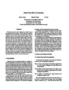
Fig. 1. A section of 2D RP from slit scanning. Different horizontal contrasts appear at different depths.
To create the route panorama, we collect temporal data continuously from the slit of one pixel width, which generates an RP image with time t coordinate horizontally and the slit coordinate y vertically (Fig. 1). A fixed sampling rate m (frame/sec), normally selected as the maximum reachable rate of the camera, is used for the scanning. At each instance or position on the path, a virtual camera system O-XYZ(t) can be set such that the image frame is vertical and the X axis is aligned with the moving direction V. Within each PoS, we can linear-transform data on the slit l to a vertical slit l’ in O-XYZ(t). This converts a general RP to a basic one that has a vertical and smooth image surface along the camera path. A 3D point P(X,Y,Z) in O-XYZ(t) has the image projection as
44
J.Y. Zheng and M. Shi
I ( x, y, t ) : x = Xf Z , y = Yf Z
(1)
where f is the camera focal length. The projection of P in the basic RP is then I (t , y ) = I ( x, y, t ) ' , calculated by x∈l
I (t , y ) : t = S r , y = Yf Z , r = V m
(2)
where V=|V|, S=|S|, and r (meter/frame) is the camera sampling interval on the path. We define a path-oriented description of the camera rather than using viewpoint orientated representation. As depicted in Fig. 2, the camera moves on a circular path with a radius of curvature R=1/κ, where κ0 for convex, linear, and concave paths, respectively. The camera translation and rotation velocities are V(V,0,0) and Ω(0,β,0), where β is a piece-wised constant related to the vehicle steering status and is estimated from GPS output. Because V is along the tangent of the path, a four-wheeled vehicle has a motion constraint as V =
∂ S (t ) = Rβ ∂t
(3)
where R and β have the same sign.
Fig. 2. Relation of circular path segments and the camera coordinate systems. (a) Convex path where R0.
On the other hand, the relative velocity of a scene point P(X, Y, Z) to the camera is ∂ P (t ) = −V + Ω × P (t ) ∂t
∂( X (t) Y(t) Z(t)) = −(V 0 0) + (0 β 0) × ( X (t) Y(t) Z(t)) ∂t
(4) (5)
When the point is viewed through the slit at time t, i.e., the point is on PoS, we have ∂ X (t ) = −V + β Z ( t ) ∂t
∂ Y (t ) =0 ∂t
β Z (t ) ∂ Z (t ) = − β X (t ) = − ∂t tan α
using tanα=X/Z. Taking temporal derivative of (1), the image velocity v is
(6)
Depth from Stationary Blur with Adaptive Filtering
v=
∂X ∂t ∂X ∂t ∂ Z (t ) ∂ t ∂x ∂ Z (t ) / ∂ t = f − fX = f −x 2 ∂t Z (t ) Z (t ) Z (t ) Z (t )
45
(7)
Filling in the results from (5) and (6) into (7), we obtain the image velocity on slit l as v=−
f (V − β Z ( t )) xβ fV V x + =− + (f + ) Z (t ) Z (t ) R tan α tan α
(8)
From (8), the depth Z(t) and the 3D point can be obtained by Z (t ) =
f 2V
fV = V x V (f + )− v (f R tan α R
2
X (t ) =
+ x ) − fv 2
Z (t ) tan α
, Y (t ) = Z (t ) y
(9)
f
where image velocity vZj
Overlapped sampling Justsampling
|v|π/4
|v|=1
=π/4
Stationary blur in RP No blur
wider than in image Same as in image
|v|>1