Depth Image-based Modeling of Point Cloud WEI Shuangfeng
CHEN Hong
School of Geomatics and Urban Information Beijing University of Civil Engineering and Architecture 1 Zhanlanguan Road,Xicheng District,Beijing 100044,China e-mail:
[email protected]
China Institue of Geotechnical Investigation and Surveying, 177 Dongzhimen Nei Street, Beijing 100007, China
Abstract—This paper introduces at first GQS(General Quadric Surface) equation,then considers that utilizing depth images referenced to various datum planes to model point cloud. After getting reference datum, this paper proposing the methods of creating depth images from point cloud and the specific steps with reference to different datums. Finally we choose some point cloud data of ancient building components from laser scanning data of Forbidden City in China as experiment data, and develop a depth images modeling system. Experiment results demonstrate the stability and high precision of the method of plane, cylinder and sphere fitting as well as the validity of depth images to represent point cloud of object. Keywords:Terrestrial Laser Scanning, point cloud; depth images; datum plane; datum cylinder; datum sphere; datum fitting
I.
INTRODUCTION
With the emergence and development of 3D laser scanning technology,it provides us a new means to capture 3D spatial information which can be quickly digitized.The technology supports the development of information digitization with the necessary existing circumstances.It supplements each other means to capture spatial data to serve for the people.and it has gained more attention in many fields such as Geoinformatics etc.Meanwhile,the process and management aroud point cloud data acquired from laser scanner become an all-important problem which is necessary to solve.
E-mail:
[email protected] point clouds in the light of the feature of the acient building(Zhang R.J.,2006).The point clouds that has been splited is regarded as the research object in this paper .The author’s main idea is to do the research about how to form range picture from messy point clouds and at the same time author propose an optimal algorithm about how to fit cylndrical surface from messy clouds point ,a method about forming range image with 3 different kind of reference datum and also a rapid interpolation algorithm based on grid index. Section 2 in this paper compare and analysis the characters of both range images and point cloud ; Section 3 simply introduce about some quadric camber equation based on general quadric surface. model ,such as plane, cylindrical surface, spherical surface and so on;Section 4 indroduce range image datum referan including the fit method about plane, cylindrical surface, spherical surface ;Section 5 introduce how to get datum to interpolate to form a range image on according to point clouds;At last ,the related algorithm is checked and analysed by experiment in Section 6.
To model, organize and manage the 3D point cloud data. This paper considers that utilizing depth images referenced to various datum planes to express point cloud of a characteric object.The main thought is in the following: extending the reference frame of range image to datum plane, datum cylinder and datum sphere,which are regarded as reference frame in different coordinate system for generating relevant range images from point cloud to express spatial object. datum plane, datum cylinder and datum sphere belong respectively to different local coordinate systems such as 2D rectangular plane coordinate system, cylindrical coordinate system and spherical coordinate system.The relation geometrical translation between local coordinate systems and global coordinate systems need to be built when reference datums are established.Finally depth images are created from 3D scattered point cloud refer to fitting datum with certain cell size specified.
II. DEPTH IMAGE AND POINT CLOUD We firstly compare and analysis the characters of both range images and point cloud ,and the difference between them.Their definitions are decripted in the following:Point cloud- A collection of XYZ coordinates in a common coordinate system that portrays to the viewer an understanding of the spatial distribution of a subject. It may also include intensity or colour information. Generally a point cloud contains a relatively large number of coordinates in comparison with the volume the cloud occupies(Barber D.M.,Mills J.P.and Bryan P.G,2003).Range images are a special class of digital images. Each pixel of a range image expresses the distance between a known reference frame and a visible point in the scene. Therefore, a range image reproduces the 3D structure of a scene. Range images are also referred to as depth images, depth maps, xyz maps, surface profiles and 2.5D images.Range images can be represented in two basic forms. One is a list of 3D coordinates in a given reference frame (cloud of points), for which no specific order is required. The other is a matrix of depth values of points along the directions of the x,y image axes, which makes spatial organization explicit ( Helmut Cantzler,2004).
After that we use three-dimensional laser scanning to get the data about point clouds and registering,we split and acquire
In this paper concepts of range images and depth images are same. Obviously point cloud is one form of depth
images.Nowdays management of point cloud has disadvantages such as we could not query feature object that we are interested in among cloud of points.Contrasting to scattered cloud of points ,we can discover that the second form of depth images with depth values matrix has some advantages on expression,management and spatial analysis in the following : (1)Flexible reference frames.We can adopt discretional 3D point as datum point,3D line as datum line or 3D plane as datum plane to calculate the depth values of points reference to them.(2)Low dimension.Depth Images store the distance between point and refrence frames with a matrix of depth values and reduce the data dimensions to one dimension which lessen the data storage.(3)Data Standardization.The expression of a matrix of depth values make data more standard.(4)Easy to sptial analysis.Depth Images is similar to DEM(Digital Elevation Model),so we can be convenient for spatial analysis such as volume computing, acquirement of section plane draw and so on. So based on the strongpoint of depth images above. We put forward the idea of modeling of Point Cloud based on depth images.. III.
PREQUADRIC CAMBER MODEL
F ( x , y , z ) = c1 x 2 + c2 y 2 + c3 z 2 + c4 xy + c5 yz + c6 xz + c7 x + c8 y + c9 z + c10 = 0 (1)
We call it general quadric surface(GQS),such as spherical surface, cylndrical surface, conical surface, paraboloid, hyperbolical surface, elliptical area and so on,in which spherical surface, cylndrical surface and conical surface is called as natural quadric surface(Lizisheng,1983).In the acient buiding models,the surface of them is usually composed as plane and natural quadric surface,but seldom quadric camber.The plane equation
The normal form of spherical equation: c7 ⎧ ⎪ x0 = − 2 ⎪ ⎪ y = − c8 ⎪⎪ 0 2 F ( x, y, z ) = x 2 + y 2 + z 2 + c7 x + c8 y + c9 z + c10 = 0 ⎨ c ⎪ z0 = − 9 2 ⎪ ⎪ 2 2 2 ⎪ R = c7 + c8 + c9 + −4c10 ⎪⎩ 2
(4)
cylndrical surface equation: F ( x, y, z ) = [( x − x0 )m − ( y − y0 )l ]2 + [( y − y0 )n − ( z − z0 )m]2 + [( z − z0 )l − ( x − x0 )n]2 − R = 0
x0 , y0 , z0 , l , m, n, R
Where
is
cylndrical
(5)
surface
o = ( x0 , y0 , z0 ) is a point in axis of cylndrical a = (l , m, n) represent unit vector of axis of surface,
paraneter,
Conical surface equation: F ( x, y , z ) = [( x − x0 ) m − ( y − y0 )l ]2 + [( y − y0 ) n − ( z − z0 ) m]2 + [( z − z0 )l − ( x − x0 ) n ]2 −
( x − x0 )2 + ( y − y0 ) 2 + ( z − z0 ) 2 sin θ = 0
In which ,a,b,c,d is regard as plane parameter,n=(a,b,c) represent plane normal vector.Plane can also be shown as quadric camber,that is:
⎧a = c7 ⎪b = c ⎪ 8 F ( x, y, z ) = c7 x + c8 y + c9 z + c10 = 0 ⎨ ⎪c = c9 ⎪⎩d = c10 So,plane can also be regarded as the degenerating form of quadric camber. This kind of feature surface will be discussed mainly refering plane and natural quadric surface. Spherical equation (3)
(6)
x0 , y0 , z0 , l , m, n, θ is conical surface parameter, p = ( x0 , y0 , z0 ) is the vertex of conical surface, Where
a = (l , m, n) is the unit vector of conical surface axis’s direction,
(2)
F ( x, y, z ) = ( x − x0 ) 2 + ( y − y0 ) 2 + ( z − z0 ) 2 − R = 0
semidiameter of sphere.
cylndrical surface,R is the semidiameter of cylindrical surface.
In three-dimensional space,if like sucn equation as follows:
ax + by + cz + d = 0
x0 , y0 , z0 , R represent spherical parameter, o = ( x0 , y0 , z0 ) represents the center of sphere,R is In which,
θ
is the half apex angle of cone of conical surface. IV.
THE DATUM FIT OF RANGE IMAGE
In order to set up differrent kind of range image model with different datum reference as has been said before .At first, datum must be fitted to form range image according to clouds point.This section mianly introduce fit method of range image about plane,cylindrical surface,spherical surface and so on.. While fit datum,the data is clouds point that has been splitted in the light of feature,this paper propose that using least square method to collect clouds point and then fit the plane datum with these points.With regard to cylindrical surface dattum fit,fitstly,we should estabilish parametric equation about cylindrical surface distance function,and then fit initial value with the method of part paraboloid and Gauss map,finally,we use Levenberg-Marquardt method to get the final value about non-linear least square. Concerning spherical surface datum fit,we could use non-linear least square method about geometry distance function parameterization,also method about linear least square.Then ,we will sepatately introduce the fit method about plane,cylindrical surface and spherical surface.
V.
⎡ cos θ ⎢ 0 =⎢ ⎢ − sin θ ⎢ ⎣ 0
GENERATION OF RANGE IMAGE
Using the reference datum which we get from the fitting algorithm, we can generate the rangeimage from the Scattered point cloud. The process of generating the rangeimage is described as follows: •
•
According to the reference datum to be fitted, we can get the posture of the base level,such as rotation parameters and translation parameters.Then we can establish the local coordinate system of the reference datum. After the Three-dimensional point cloud is projected onto the reference datum, we can get two-dimensional X, Y coordinates and calculate the distance between points to the value of projecting plane; Form the collection of three-dimensional point cloud which is located in the Local coordinate system.,at the same time to determine the coordinates of points in the coverage of projecting plane.
•
According to the space of the grid interpolation, we divide the coverage of coordinate and generate the regular grid which is in uniformly-spaced.
•
According to the collection of point cloud which is located in the Local coordinate system, we get the interpolation of the distance between these grid points and the base-level and generate a new rangeimage.
It can be seen from the above process, the critical problems of generating the range image are the determination of the base-level posture,the spacing of grid interpolation and the strategies and methods of interpolation located in different local coordinate systems. Then I will give a corresponding introduction of some problems. A.
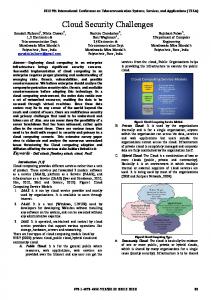
Determination of the base-level posture The base-level posture is in accordance with the profile fitting parameters to obtain the base-level datum plane of rotation, translation parameters. For the Datum plane, we can determine the rotation angle according to the Normal direction of fitting plane, and the translation vector can be determined by the new starting point of the plane. For the Cylindrical surface datum, the rotation can be determined by the Axis direction and the translation is determined by the new starting point of the cylindrical surface. If we get the core coordinates of the Spherical, we can determine the spherical posture. Then we will discuss the calculation of the base-level posture 、 the cylindrical surface datum posture and the spherical datum posture. 1) Plane posture In Figure 1,supposing that the plane we got is one rotating
ϕ °clockwise around x-axis and then rotating θ °around yaxis anticlockwise,the rotating matrix is ⎡ cos θ ⎢ 0 M = Ry (θ ) Rx (−ϕ ) = ⎢ ⎢ − sin θ ⎢ ⎣ 0
0 sin θ 1
0
0 cos θ 0
0
0 ⎤ ⎡1 0 0 ⎥⎥ ⎢⎢0 cos ϕ 0 ⎥ ⎢0 − sin ϕ ⎥⎢ 1 ⎦ ⎣0 0
0⎤ 0⎥⎥ cos ϕ 0⎥ ⎥ 0 1⎦ 0
sin ϕ
− sin θ sin ϕ cos ϕ
sin θ cos ϕ sin ϕ
− cos θ sin ϕ 0
cos θ cos ϕ 0
After M transfer,direction vector of z-axis turn to be
0⎤ 0 ⎥⎥ 0⎥ ⎥ 1⎦
nz = (0, 0,1)
nz' = Mnz = (sin θ cos ϕ ,sin ϕ , cos θ cos ϕ ) After
M
transfer,direction
vector
of
x-axis
vector
of
y-axis
nx = (1, 0, 0) turn to be: nx' = Mnx = (cos θ , 0, − sin θ ) After
M
n y = (0,1, 0)
transfer,direction
turn to be:
n = Mn y = (− sin θ sin ϕ ,cos ϕ , − cos θ sin ϕ ) ' y
The normal vector of plane turn to be plane normal vector value after fitting is n = ( nx , n y , nz ) = (
a1 2 1
2 2
a + a +1
,
a2 2 1
2 2
a + a +1
nz' ,
after rotation,e.g −1 2 1
a + a22 + 1
)
ϕ
So θ and can be defined through formulas above,meanwhile new direction vector of x -axis and y-axis can be got by these. Supposing that the origin can be got like that plane xoy ϕ ° and then rotate rotate around x-axis clockwise about around y-axis anticlockwise about '
' o
' o
' o
θ
°,we can get origin
o (x , y , z ) by translation.As o is on the plane and JJJK ' oo = kn ,we can get translation vector from plane xoy to '
fitting
plane,e.g.
−a a −a a a o ' ( xo' , yo' , zo' ) = ( 2 0 2 1 , 2 0 2 2 , 2 0 2 ) a1 + a2 + 1 a1 + a2 + 1 a1 + a2 + 1 .
2) Cylindrical poseture Cylindrical poseture can be defined by cylindrical patameter from the paper (Wei S.F.,2006).We will get 5 patameters through fit usingLevenberg-Marquardt '
method.Then axis direction a,point o on axis and radius should be calculated.According to cylindrical patameterizaton principle,cylindrical radius r is 1/ κ ,coordinate
1 o + ( ρ + )n
o ' is
κ .At the same time,local coordinate system should be defined in order to the interpolation of clouds point.The concrete algorithm is as showm below:
Regarding the nearst point close to cylinder central axis points as the origin of cylinder coordinate system,and axis as Z1,meanwhile supposing Z1 is Z-axis that is to say ϕ vector(0,0,1)rotate around x -axis clockwise about °,we can get a after tanslation ,if we rotate Z1-axis around y-axis about
θ
°。Where the rotation angles value.So we cake conclude that: ⎡ cos θ ⎢ 0 M = Ry (θ ) Rx ( −ϕ ) = ⎢ ⎢ − sin θ ⎢ ⎣ 0
⎡ cos θ ⎢ 0 =⎢ ⎢ − sin θ ⎢ ⎣ 0
ϕ
and
0 sin θ 1 0 0 cos θ 0 0
θ
are both positive
0⎤ ⎡1 0 ⎥ ⎢ 0⎥ ⎢ 0 cos ϕ 0⎥ ⎢ 0 − sin ϕ ⎥⎢ 1⎦ ⎣0 0
− sin θ sin ϕ sin θ cos ϕ cos ϕ sin ϕ − cos θ sin ϕ cos θ cos ϕ 0 0
0⎤ 0 ⎥⎥ 0⎥ ⎥ 1⎦
After M transfer ,direction vector of z-axis turn to be:
ϕ and θ
nz = (0, 0,1)
can be got from formula above.
While going through M transfer, direction vector of y-axis
n y = (0,1, 0)
turn to be:
n'y = Mn y = (− sin θ sin ϕ ,cos ϕ , − cos θ sin ϕ ) So direction vector of x-axis turns to be X1-axis after M transfer:
n = Mnx = (cos θ , 0,sin θ ) ' x
Finally, we can get coordinate system named X1-X2-X3 in the global coordinate system. 3) Spherical Posture As spherical surface has great symmetry, it’s OK that we
( x , y , z0 ) and
should only know spherical center coordinate 0 0 radius R in the process of ensuring spherical posture.
We need to take the fitted spherical center coordinate O1
O1 ( x0 , y0 , z0 ) as coordinate origin, and regard global direction of coordinate axis as the axis direction of coordinate system so called X1-Y1-Z1. B.
p
where the plane located. Set the coordinate point is i , under the new coordinate axis posture, according to the definition of the dot product(wang shengrui,2006),the coordinates of
pi in
JJJK JJJK 0⎤ ' ' ' o pi ⋅ n 'y 0 ⎥⎥ the new coordinate system is ( o pi ⋅ nx 、 JJJK 、 JJJK JJJK ' ' cos ϕ 0 ⎥ ' ' ' ' ⎥ o pi ⋅ nz ), o pi ⋅ nx is the value of X-coordinate, o pi ⋅ n y 0 1⎦ JJJK 0 sin ϕ
nz' = Mnz = (sin θ cos ϕ ,sin ϕ , cos θ cos ϕ ) = a So
1) The range image interpolation of Datum plane After ascertaining the spatial attitude of planar reference surface, we should calculate the new coordinate of every point relative to the plane, according to the new coordinate system
Interpolation method of range image After ensuring the datum posture and the size of interpolation grid, we can get the range image according to the step 4.3.The main problem of grid interpolation is at the ensurance of domain and the choice of the interpolation method. The main research model of this section is the method and step of resampling.
o' p ⋅ n'
i z is the Z values of is the value of Y- coordinate, elevation .After we get the collection of the point cloud in the new coordinate system , calculate the number of rows or columns of the grid interpolation according to the grid interval, then do the interpolation of each grid. Then we will describe the method interpolation below.
The construction of regular grid can be got directly from the discrete points of space data, or setting up the data about TIN first and then do the interpolation of TIN .In order to reduce the computation, we use the method of generating the regular grid from the discrete points directly. It always adopts the method of the interpolation from point to point. The basic principle is that make the point to be inserted as the center, then define a partial function to fit the data points around(Reference point), The scope of data points is changed with the location of the point ( Li Z.L.,Zhu Q.,2000 ) .There are so many interpolation methods, such as Mobile surface fitting, Distance weighting method, Finite element interpolation, Cone Construction Law and so on, the first two methods are used more widely. As for the mobile surface fitting method, To insert in each of its points, many reference points around are chose to fit a polynomial surface, the formula M = Ax 2 + Bxy + Cy 2 + Dx + Ey + F is adopted, there x, y is the coordinate of every reference point, the M is the attribute value, A、B、C、D、E、F is undetermined parameter, it can be calculated by using the least square method. As for the distance-weighted method, the formula n
n
i =1
i =1
Z p = ∑ pi Z i / ∑ pi
is adopted; there
Zp
is the elevation of
p Z the undetermined point . i is the elevation of the reference
point i, n is the number of the reference point, Pi is the weight of the point .As for moving average method, many complicated error equations have to be soluted. In practical application, the distance-weighted method is used more commonly; this method is the special case of moving average method, Instead of using the weighted average of the error equations when the elevation of the undetermined point p is soluted. So the distance-weighted average method is adopted in this thesis. Choosing ten points which are nearest to the point p for fitting. The weight is
pi = 1/ ri 2
, there
ri is the distance between
point p and each reference points. There are two methods for searching the nearest point. The first method is that when we search for the nearest point we should search all points around to find out the nearest ten points, this method is called Ergodic interpolation. But the efficiency of this method is very low when it is used for the data about large-scale three-dimensional point cloud. So in order to improve the efficiency, grid indexing is adopted, that is fast interpolation which is based on grid index, named Index Grid interpolation. 2)
database. When the range image of cylindrical datum is read from database and displayed, we anti-calculate the point about x-coordinate ,y-coordinate and altitude value in the stretching
(x
,y
,z
)
plane dem dem dem to global coordinate, the calculating formula about coordinate is shown as follows:
θ = xdem / r + θ min x = (z dem +r)* cosθ y = (z dem +r)* sinθ
Range image interpolation of cylinder datum
After ascertaining the space posture of cylinder referance plane, we can devided the range image interpolation of cylinder datum into 3 steps: a) Calculation about clouds point parameter According to the fitted cylinder axis vector and the axis equation that is defined by a point on the axis,after ascertaining the posture of cylinder datum and local coordinate of cylinder,we can calculate the aggregation of 3-dimensional clouds point in whicn contains clouds point in the local coordinate,then according to the parameter equation:
⎧ x = r cos θ ⎪ ⎨ y = r sin θ ⎪z = h ⎩ Cylindrical parameter
0 ≤ θ < 2π , −∞ < h < +∞
plane,supposed
θ
θ
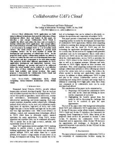
3) Range image interpolation of spherical datum After defining the spacial posture of spherical surface datum, the range image interpolation of spherical surface datum can be divided int three steps: a) Ensure latitude and longitude of cloouds point on sphere We take the fitted spherical center point
O (x , y , z )
1 0 0 0 as coordinate origin,and do coordinate direction of global coordinate axis as the axis direction of spherical surface coordinate X1-Y1-Z1.Next we calculate the 3-dimensional clouds point coordinate in new coordinate
system,and then calculate included angle
θ
and h can be got.
b) X-coordinate ,y-coordinate and the altitude of the interpolation points After getting
z = ydem
and h,we should stretch cylinder to
is min and h is min ,meanwhile,the point on
(θ
,h )
the cylindrical surface is op( min min ),supposed the line that is parallel to op is y-axis,and x-axis is streched by op’s generatrix,the value of x-coordinate,y-coordinate and
(x , y , z ) altitude dem dem dem could be calculated as follows: Supposing the radian from a point to op is x-coordinate of cylindrical coordinate that has been stretched,so we can get that
xdem = r *(θi − θ min ) ,where r is the radius of cylinder,e.g. radius value 1/ κ got when fitting cylinder;value z in the new
coordinate system is taken as y-coordinate after spreading cylindrical surface;The direction value from a point in new coordinate system to cylidrical datum is taken as the direction 2 2 value about range image,e,g, zdem = x + y − r .
c) Point direction value interpolation about range image grid According to x-coordinate and y-coordinate of interpolation, we can ensure the coordinate coverage of interpolation point ,e.g.,minimum bounding rectangle (MBR).Then we should devide grid in the light of interval of interpolation grid, and interpolate the value of grid interval through traversal interpolation method or grid index . Finally, the range image data model is established and saved in
O1 Pi
λ
between Z1-axis
'
O1 Pi that is from a point to X OZ center of sphere which is projected at plane 1 1 1 ,we call it
and the line
projected by line
longtitude.Its scale is from
ϕ
−180D to 180D .The included angle O1 Pi ' X 1O1Z1
which is formed between
and plane
calculated too,we call it latitude.Its scale is from
will be
−90D to
90D (see Figure 3). b) Calculation of x,y-axis and altitude value of interpolation point Supposing that
λ
ϕ is min with the point on the (λ , ϕ ) op min min ,the algorithm about
is min and
spherical surface being
point’s x,y-coordinate and altitude value as follows:
( xdem , ydem , zdem ) is
Supposing that the x-coordinate value is derived from longtitude minusing
O1 Pi
λmin ,we can get that xdem = λi − λmin . x-
coordinate value is derived from
O1 Pi latitude minus θ min ,e.g.
ydem = ϕi − ϕmin ;The direction of range image is derived
from the distance of one point to spherical surface datum in 2 2 2 new coordinate system, e.g. zdem = X + Y + Z − r ,where r is the fitting spherical radius ,(X,Y,Z) is the coordinate in X1Y1-Z1 coordinate system. c) image
Distance value interpolation of clouds point range
Based on the X-coordinate and Y-coordinate of the interpolation points which are calculated above, to determine the coverage of the coordinates of interpolation points, that is the scope of latitude and longitude of the spherical, then divide the coverage into spherical grid with the spacing of the interpolation grid, and use Ergodic interpolation or Index Grid interpolation for the value of grid point interpolation. Finally, generate the Range Image Data Model and deposit the model to the database. When we read and display the range image of the
(x
,y
,z
•
Different method about fitting plane, cylindrical surface and spherical surface is proposed, also new optimization algorithm cylinder fit about using Guass mapping to get initial value. The stability of the algorithm is then analyzed by experiment comparison.
•
The steps of generating the depth image are proposed, the depth image is generated through fitting to be planar, cylindrical, spherical which is taken as the reference datum. As for the interpolation of the massive point cloud, the fast interpolation algorithm method which is based on the grid index is proposed, and it is proved by experiment that the high efficiency of the Index Grid interpolation. And the automatic method of calculating the size of the grid interpolation.
•
It has been vertified by experiment that the correctness of the method of fitting to the planar, the cylindrical, the spherical surface and the method of generating the depth image.
)
datum cylindrical, and anti-calculate dem dem dem to the global coordinate system, the formula for calculating its coordinates is as follows: λ = xdem + λmin ϕ = xdem + ϕ min X = (z dem +r)* cosϕ sin λ Y = (z dem +r)* sinϕ Z= (z dem +r)* cosϕ cos λ
VI.
ACKNOWLEDGMENT
EXPERIMENTS ANALYSIS
A. The fit of plane datum The process of fitting plane datum is as follows:firstly,open data bout clouds point on plane,then use the method of least square to get the plane datum,and then the range image will be got by interpolation according to assigned grid resolution(Figure 4). B.
The fit of cylindrical datum 3D laser scanning data, which is used in digital surveying project in the Imperial Palace, is adopted by this article to do the experiment. Figure 5 is the result which is got from fitting after determining initial value by Gauss projection method in the paper( Wei S.F.,2006). The stability of the algorithm is proved by experiment comparison.
Figure 8 shows Depth images of Taihemen of Forbidden City in China in the depth images modeling system in Visual C++ Integration Development Environment with OpenGL graphics library. . C.
The fit of spherical datum As is shown in Figure 6,it is a pictureof clouds point that present steel structure’s girder sphere node of national indoor stadium.In Figure 7,the red part is spherical surfance datum got by fitting through linear least square. VII. CONCLUSION
This article start from the normal equation,and study the methodof fiting plane datum,cylindrical surface datum and spherical surface by making use of 3-dimentional clouds point,then proposes cylinder fit optimization algorithm about how to use Guass mapping to get initial value.The datum’s posture and new coordinate is defined by model parameter through fitting,then the range image is resampled in new coordinate,finally real range image is formed. The main innovation in this paper:
This publication is an output from Project “Research on Spatial Data Organization and Management for Terrestrial Laser Scanning Data Based on Range Images” supported by National Natural Science Foundation of China ( No. 40801159),Funding Project for Academic Human Resources Development in Institutions of Higher Learning Under the Jurisdiction of Beijing Municipality(No. PHR 20070101) and the project of " “Research on Spatial Data Organization and Management for Terrestrial Laser Scanning Data Based on Range Images " supported by the Scientific Research Foundation of Beijing University of Civil Engineering and Architecture. REFERENCES [1]
[2]
[3] [4]
[5]
[6]
[7]
[8]
Barber D.M.,Mills J.P.and Bryan P.G.Towards a standard specification for terrestrial laser scanning. International Archives of Photogrammetry and Remote Sensing, 34(5/C15): 619-624.2003 Helmut Cantzler.An overview of range images.2004.http://homepages.inf.ed.ac.uk/rbf/CVonline /LOCAL_COPIES/CANTZLER2/range.html Li Z.S., Analytic geometry of space Shandong Education Press. 1983 Zhang R.J.,“Study on 3D reconstruction technoloy of ancient architecture based on 3D laser scanning data”,Ph.D. dissertation of Wuhan University,Wuhan,2006 Wei S.F.,Wanf Y.M.,An Optimized Method for Cylinder Fitting in Range Image JOURNAL OF ZHENGZHOU INSTITUTE OF SURVEYING AND MAPPING .2007,24(5),PP.281-283 Liu Y.P.,Zhang D.H.,“Study on Evaluation of Cylinder Geometric Parameters in Reverse Engineering”.Mechanical Science and Technology.Xi’an,2005. 24(3),pp. 310-311 Chaperon T, Goulette F.Extracting cylinders in full 3D data using a random sampling method and the Gaussian Image[A]. In: Vision, Modeling and Visualization, Stuttgart, VMV[C], 2001:35-42 Li Zhilin, Zhu Qing. Digital elevation model. Wuhan University Press .2000
[9]
Coorg S.teller S.Real-time Occlusion Culling for Models with Large Occluders.ACM Symposium on Interactive 3D Graphics.pp:83-90.1997 [10] Douglas D H and Peucker T K. Algorithms for the reduction of the number of points required to represent a digitized
Figure 1 plane posture
line or its caricature. The Canadian Cartographer, 10(2): 112-122, 1973. [11] G. Roth and M. D. Levine Geometric primitive extraction using a genetic algorithm[J].IEEE Transactions on Pattern Analysis and Machine Intelligence,1994,16(9):901-905.
Figure 2 cylinder posture
Figure 4 Depth image based on datum plane
Figure 6 Initial clouds point about sphere
Figure 3 Point calculation of longtitue and latitude
Figure 5 Depth image based on datum cylinder
Figure 7 Fitting sphere from point cloud
Figure 8 Depth images of Taihemen