dependant on real time data processing and execution. ... 2.1 Hardware Modeling of the Humanoid ... device by Microsoft for XBOX 360 video game console.
IOSR Journal of Electrical and Electronics Engineering (IOSRJEEE) ISSN : 2278-1676 Volume 1, Issue 1 (May-June 2012), PP 31-37 www.iosrjournals.org
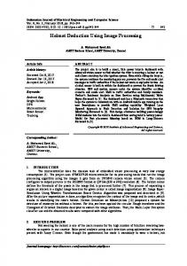
Depth Image Processing and Operator Imitation Using a Custom Made Semi Humanoid Ghanshyam Bhutra1, Piyush Routray2, Subrat Rath3, Sankalp Mohanty4 1
(Dept. of EEE, S‘o’A University, India) (Dept. of E&I, S‘o’A University, India) 3(Dept. of EEE, S‘o’A University, India) 4 (Dept. of EEE, S‘o’A University, India) 2
ABSTRACT : The motivation for creating humanoids arises from the diverse socio-economical interests ranging from the restoration of day-to-day activities of differently abled to assisting humans in nearly inaccessible areas such as mines, radiation sites, military projects, etc. Recent developments in the field of image processing, thus enabling depth imaging and skeleton tracking easily has greatly increased the potential of accurately inferring the signals of human operator. The time constraints on various jobs make them grossly dependant on real time data processing and execution. Also, the acceptance by the industrial community depends on the accuracy of the complete system. The objective is to develop a proof based accurate system to assist human operation in potentially inaccessible areas. The system has to analyze image feed from the camera and deduce the gestures of the operator. Then the system communicates wirelessly with the self designed SemiHumanoid which in-turn, imitates the operator with maximum accuracy.
Keywords – Humanoid Robot, MATLAB, Microsoft Kinect, Servo Motor, Skeleton Tracking. I.
INTRODUCTION
Humanoid robots, in the future, seem to be the best alternative for human labor. Communication at work place environment greatly depends on body movements apart from direct audio signals. While verbal signals give brief idea of the details of the work to be done, it is the physical demonstration that tends to have maximum impact. Much work has progressively been done in the fields of gesture recognition and implementation [1]-[3]. However, with advent of comparatively cheaper and easy to use depth imaging techniques such as Microsoft Kinect, the accuracy of gesture recognition can be increased to greater percentage. Perfect imitation of the human, by a robot, requires tremendous calculations and harmonious work of many different aspects of the system. A common form of mobile robot today is semi-autonomous, where the robot acts partially on its own, but there is always a human in the control loop through a link i.e. Telerobotic. In this technique, there are no sensors on the bot, those it may use to take a decision. One of the possible methods of controlling such a bot is by amalgamation of depth imaging and skeletal tracking of the human operator. For extending the area of application of the bot, it has to be wirelessly controlled and equipped with fine maneuvering techniques. The signal transmission demands many-to-many communication with optimum use of bandwidth and data protection. If achieved with maximum accuracy this technology stands to be of great applications at outer space exploration, remote surgeries, hostile industrial and military conditions, security purpose and of course, gaming and recreational activities.
II.
APPROACH
The approach to the problem was made on a calculated basis by first simulating on software and then implementing as hardware. Broadly, the approach can be divided into four categories dealing with different works. Successive amalgamations of the acquired results lead to the final goal. First step is to model the Humanoid. It is followed designing of the control architecture, which is the suite of control required for behavioral synchronization between human and the BOT. Next step caters to the acquisition and processing of image feed from the Kinect sensor. Thus, the controlling parameters are determined here. Final step involves wirelessly transmitting the inferred values of the controlling parameters to the Bot. the microcontrollers (mcu) used in the robot decodes these parameters and thus redirects the robot to react accordingly. The approach has been discussed thoroughly through the following paragraphs.
www.iosrjournals.org
31 | Page
Depth Image Processing and Operator Imitation Using a Custom Made Semi Humanoid 2.1 Hardware Modeling of the Humanoid The software design was readied with 6 Degrees of Freedom. The model was divided into various links and every link was modeled individually in the SolidWorks software. All the links were mated and ADAMS was used to test the model under real physics by simultaneously solving equations for kinematics, statics, quasistatics and dynamics for multi-body system. Specifically for simulation purpose, the virtual model is designed based on principles of kinematic modeling by Denavit-Hartenberg methodology for robotic manipulators [4]. There are total 18 Degrees of Freedom (DOF). Each arm has 5 DOF and each leg has 4 DOF. (Fig.1)
figure 1. Adam‟s plant model of humanoid for simulation. The destination coordinates are fed into the ADAMS plant which has been configured to take input in the form of angular velocities and output the current joint angles. The ADAMS plant is executed in MATLAB (Simulink) environment with a function file to control it. The stability of the humanoid was inspired from previous works done in this regard [5] – [8]. There are two separate methods to control the motion of a humanoid i.e. DC (Direct Control) and CC (Command Control).Direct Control performs the conversion of 3D joint coordinates of the user to servo angles whereas the Command Control converts information to a single command for the robot‟s understanding. The information that is sent is the destination positions for the tool frame and the calculation of joint angles is left for the model. For gain of maneuvering options in terms of speed and simplicity for most cases, the biped locomotion was voted against in favor of wheeled maneuvering system. Next step was to construct the hardware model. The material for construction was chosen to be Aluminium and 6 Servo Motors of the rating 60g/17kg/0.14sec were used. For the base of the BOT, four motors, two each of the rating 12V, 250 rpm, 60Kgcm and 12V, 250 rpm, 30Kgcm were used. To regulate the speed of the driving motors, PWM was executed with Motor Drivers. The gross weight of the BOT is 10kg (approx.) including the weight of the BECs (Battery Eliminator Circuits) and Power Supply. LiPo Batteries of the rating 11.1V, 6000 mAh 25~50C (Qty-2) and 11.1V, 850 mAh 20C (Qty-4) have been used for power supply. The servos operate in the range 4.8V~6.0V and thus BECs were used to convert 11.1V to 6.0V. The completed structure of the robot is shown as below. (Fig.2)
figure 2. Complete structure of the robot.
Figure 3. Control architecture
2.2 Control Architecture As shown above (fig.3), for convenience this has been described in two parts, AVR Controller and ZIGBEE Communication. The AVR microcontroller that has been used is ATMEGA 32 which is an 8-bit MCU. This controls the servo motors and the driving motors. There are in-total 10 motors to be controlled (6 Servo + 4
www.iosrjournals.org
32 | Page
Depth Image Processing and Operator Imitation Using a Custom Made Semi Humanoid Shunt). Four MCUs have been used, out of which three control the servos and the remaining one controls the driving motors. Each MCU has been interfaced with an LCD to continuously display its status. ZIGBEE is the standard that defines a set of communication protocols for low-data-rate, very low power applications. We are using XBee RF modules for communication. These modules interface to a host device through a logic-level asynchronous serial port. The link between XBee and ATMEGA 32 takes place via UART (Universal Asynchronous Receiver/Transmitter). The data format and transmission speeds are configurable. The AVR CPU connects to AVR UART via six registers i.e. UDR, UCSRA, UCSRB, UCSRC, UBRRH and UBRRL. 2.3 Depth Image Processing & Gesture Interpretation. Depth Imaging is the central point of this publication as it can be considered a giant leap in terms of boosting accuracy while operator imitation. The sensor being used is Kinect which is a motion sensing input device by Microsoft for XBOX 360 video game console. It is a horizontal bar connected to a small base with a motorized pivot and is designed to be positioned lengthwise. The device features an "RGB camera, depth sensor and multi-array microphone running proprietary software", which provide full-body 3D motion capture, facial recognition and voice recognition capabilities. The depth sensor consists of an infrared laser projector combined with a monochrome CMOS sensor, which captures video data in 3D under any ambient light conditions. The sensing range of the depth sensor is adjustable, and the Kinect software is capable of automatically calibrating the sensor based on the physical environment, accommodating for the presence of the user.
Figure 4. Kinect Sensor. Third party software and open source drivers were implemented to gain compatibility with MATLAB. At the heart of Kinect, lies a time of flight camera that measures the distance of any given point from the sensor using the time taken by near-IR light to reflect from the object. In addition to it, an IR grid is projected across the scene to obtain deformation information of the grid to model surface curvature. Cues from RGB and depth stream from the sensor are used to fit a stick skeleton model to the human body. The reference frame for the Kinect sensor is a predefined location approximately at the center of the view. The horizontal right hand side of observation denotes the x axis and transverse axis denotes y axis The z axis is the linear distance between the Kinect and user, the farther the user the higher the z value. We monitor the real time positions and orientations of 15 different data points in the user‟s body, namely: Head, Neck, Left Shoulder, Left Elbow, Left Hand, Right Shoulder, Right Elbow, Right Hand, Torso, Left Hip, Left Knee, Left Foot, Right Hip, Right Knee and Right Foot. The sensor generates a 2D Matrix of 225x7 dimension with the above mentioned datapoints for a single person. The seven columns are User ID, Tracking Confidence, x, y,z (coordinates in mm) and the next X,Y (the pixel value of the corresponding data point). Using the raw data points from Kinect, vectors are constructed and using those, the angles between different links and the lengths of different links were found. The skeletal map is obtained according to user specisified link and node colours as shown in fig.5a&b.
www.iosrjournals.org
33 | Page
Depth Image Processing and Operator Imitation Using a Custom Made Semi Humanoid Figure5 a. Skeletal mapping in low light conditions. Figure5 b. Skeletal mapping in sufficient lighting. The data points are then used to calculate and derive values ranging from link length to angular velocity as discussed in the later part. 2.4 Data transmission and Robot Control As mentioned earlier, the technology defined by the ZigBee specification is intended to be simpler and less expensive than other WPANs, such as Bluetooth. ZigBee is targeted at radio-frequency (RF) applications that require a low data rate, long battery life, and secure networking. One of the Xbee pair is connected to the PC using Xbee USB adapter board and the other one is interfaced to the Microcontroller. The data enters the module‟s UART from the serial port of the PC through the DI pin as ansynchronous serial signal. The signal should idle be high when no data is being transmitted. Each data byte consists of a start bit(low), 8 databits (least significant being first) and a stop bit. Now that the information to be sent and method of communication is ready, the next step is finding out the memory addressing technique so that the data transmitted should be in synchronization with the data received. In order to address the 10 actuated joints with a single duplex channel of 8 bit word length we had to involve an addressing strategy. The number of bits required to address 10 individual motors would ideally be 4 bits and to transmit 8 bits of data to each of the motors makes the word length of 12 bits which is not available. So instead of delivering the word in a single transmission the information is broken in 2 nibbles of 4 bit length and 2 consecutive transmissions are required to successfully transmit the 8 bit of data. With this split we had to assign 1 bit to distinguish between the higher and the lower nibble which again created a problem as the word length of a transmission is limited to 8 bits only. Two separate 4-bit address for each motor are used to send the higher and lower nibble of data from the source. This scheme allows us to address a 40 maximum of 256 different addressees and transmit information of 8 bits to each one in 2 consecutive transmission. The analogy, for betterunderstanding can be presented as in fig.6.
Figure 6. Diagramatic analogy of communication method. After the reception of the control signal at the remotely located manipulators the microcontrollers controlling the servos decodes the servo angles from the control signal and implements it. Controlling a servo using a microcontroller requires no external driver like H-bridge only a control signal needs to be generated for the servo to position it in any fixed angle. The control signal is 50Hz (i.e. the period is 20ms) and the width of positive pulse controls the angle. This implementation of the servo angle completes 1 cycle of the process as it ends with the beginning of the kinect sensor inputting the joint information to the control system. Thus, in this way the behavioral synchronization between an operator and the BOT is achieved.
III.
IMPLEMENTATION
The dynamic process of behavioral synchronization through a humanoid begins with derivation of real time information about the joints of the user be it prismatic (linear) or revolute (rotational). With degree of freedom as high as 10 the task becomes extremely tedious and requires tremendous processing power. One of the major problems in monitoring multiple joints information is the definition of the reference frame with respect to which information about the other frames can be derived. Even though the reference for individual joints may vary it is convenient to process all the joints with a single reference point. The Kinect Sensor provides this information to the central control block using a combination of infrared imaging and RGB camera. The infrared laser creates a depth profile of the area in display and the RGB camera returns RGB matrix.
www.iosrjournals.org
34 | Page
Depth Image Processing and Operator Imitation Using a Custom Made Semi Humanoid The sensor generates a 2D matrix of 225 x 7 dimension with the above mentioned data points for a single person and a maximum tracking capability of 15 people. The seven columns are User ID, Tracking Confidence, x, y, z (coordinates in mm) and the next X, Y (the pixel value of the corresponding data point). Using this information we calculate the joint angles in different planes between different links as well as the link lengths between data points. Having raw joint information is not enough for further operations, because of that on the next step the vector between joints should be constructed. As an example below a description of construction of vector between joints of right hand has been given: Connecting the right shoulder, right elbow and right elbow and palm determines the angle for right shoulder. Right shoulder = 𝑥𝑟𝑠 , 𝑦𝑟𝑠 , 𝑧𝑟𝑠 Right elbow = 𝑥𝑟𝑒 , 𝑦𝑟𝑒 , 𝑧𝑟𝑒 Right palm = 𝑥𝑟𝑝 , 𝑦𝑟𝑝 , 𝑧𝑟𝑝 Vect1 = 𝑥𝑟𝑠 , 𝑦𝑟𝑠 , 𝑧𝑟𝑠 − 𝑥𝑟𝑒 , 𝑦𝑟𝑒 , 𝑧𝑟𝑒 Vect2 = 𝑥𝑟𝑝 , 𝑦𝑟𝑝 , 𝑧𝑟𝑝 − 𝑥𝑟𝑒 , 𝑦𝑟𝑒 , 𝑧𝑟𝑒 Now the angle between the vectors is calculated by using a simple geometrical operation such as angle between two vectors. Joint angle = cos−1
𝑉𝑒𝑐𝑡 1 ∙𝑉𝑒𝑐𝑡 2 𝑉𝑒𝑐𝑡 1 ∗ 𝑉𝑒𝑐𝑡 2
Using the x, y and z coordinates derived from Kinect sensor and using the formula for distance calculation the link lengths are found. length =
(xrs − xre )2 + (yrs − yre )2 + (zrs − zre )2
After calculating the joint angles and link lengths, the next step in the behavioral synchronization would be to realize these real time parameters in the desired form. This step includes conversion of the parameters to actual servo angles. It is necessary for tuning purpose between the real angle values of joints and robot servo values. Another reason for the necessity of this step is because the real human joint angle values range from 0~360°, when the robot servo motor can accept values from 0~255. Now that the destination coordinates of the individual tool frames for the humanoid robot have been derived, two simultaneous steps follow, embedding the gesture movements into the virtual (software) and real (hardware) model. Since each arm has 3DOF, the tool frame coordinates – x, y and z depends on 3 angles θ1 , θ2 and θ3 which can be expressed as: θ1 x y = T θ2 z θ3 Here „T‟ is the transformation matrix that relates the coordinates with the joint angles. θ1 x y = J θ2 z θ3 „J‟ denotes the Jacobian matrix and x, y and z are the product of error signal of the corresponding axis and the proportionality constantk p andθ1 , θ2 and θ3 are the joint anglular velocities. x = (xdestination − x) × k p y = (ydestination − y) × k p z = (zdestination − z) × k p
www.iosrjournals.org
35 | Page
Depth Image Processing and Operator Imitation Using a Custom Made Semi Humanoid To evaluate the angular velocities, we use the expression , θ1 x θ2 = J−1 y z θ3 These angular velocities are then converted as discussed earlier and then transmitted to the Robot. The servomotors attached at designated joints thus move accordingly and operator imitation is achieved.
Figure7. Imitation of its human operator by ACE, the semi-humanoid robot.
IV.
CONCLUSION
The implemented architecture suggests simple, low cost and robust solution for controlling a semihumanoid with human gestures. The complete setup requires the synchronization of software and hardware. The above mentioned problems were faced for setting it up. This project can serve as a development platform for interaction between human and BOT via gestures and with the quality of resources of products, more sophistication can be inculcated. Presently biped motion and holding mechanism in the hands are being worked upon. The legged motion is expected to enable the robot to maneuver over uneven terrains easily than the wheels. The picking/holding mechanism would increase its applicability in the industries by manifolds. Thus the greater goal of attaining better man-machine teams for dynamic environments can be realized with perfection.
ACKNOWLEDGEMENTS We acknowledge the research facilities extended to us at Centre for Artificial Intelligence and Robotics (DRDO), Bengaluru for carrying out the simulations and learning other mechanical nuances of humanoids. We also thank faculty advisor of the ITER Robotics Club, Asst. Prof Farida A Ali for her continuous guidance and support over the period of research.
REFERENCES [1]
David Koterkamp, Eric Huber and R. Peter Bonasso, “Recognising and Interpreting Gestures on a Mobile Robot”, Thirteenth National Conference on Artificial Intelligence (AAAI), 1996.
[2]
Stefan Waldherr, Roseli Romero and Sebastian Thrun, “A Gesture Based Interface for Human-Robot Interaction”, Kluwer Academic Publishers, 2000.
[3]
Hideaki Kuzuoka, Shin'ya Oyama, Keiichi Yamazaki, Kenji Suzuki and Mamoru Mitsuishi, “GestureMan: A Mobile Robot that Embodies a Remote Instructor's Actions”, Proceedings of SCW’00, December 2-6, 2000.
[4]
John J. Craig, Introduction to Robotics, pg70-74, 3rd Edition, Pearson Education International. 2005.
[5]
Vitor M. F. Santos and Filipe M. T. Silva,
[6]
“Engineering Solutions to Build an Inexpensive Humanoid Robot Based on a Distributed Control Architecture”, 5thIEEE-RAS InternationalConference on Humanoid Robots, 2005.
www.iosrjournals.org
36 | Page
Depth Image Processing and Operator Imitation Using a Custom Made Semi Humanoid [7]
Santos, F. Silva, “Development of a Low Cost Humanoid Robot: Components and Technological Solutions”, in Proc. 8th International Conference on Climbing and Walking Robots, CLAWAR’2005, London, UK, 2005.
[8]
J.-H. Kim et al. –“Humanoid Robot HanSaRam: Recent Progress and Developments”, J. of Comp. Intelligence, Vol 8, nº1, pp.4555, 2004.
[9]
Jung-Hoon Kim and Jun-Ho Oh, “Realization of dynamic walking for the humanoid robot platform KHR-1”, Advanced Robotics, Vol. 18, No. 7, pp. 749–768 (2004)
[10]
K. Hirai et al., “The Development of Honda Humanoid Robot”, Proc. IEEE Int. Conf. on R&A, pp. 1321-1326, 1998.
[11]
[Kinect] Use With Matlab www.timzaman.nl
[12]
KINECTHACKS www.kinecthacks.com
www.iosrjournals.org
37 | Page