Jun 11, 2012 - numerous threads running in parallel over a set of shared data. In [3], the ...... used communication interfaces for modern computers are USB, ... overhead due to their 8b/10b symbol encoding scheme (used for clock recovery),.
Computing and Informatics, Vol. 31, 2012, 1001–1021, V 2012-Jun-11
DESCRIBING THE FPGA-BASED HARDWARE ARCHITECTURE OF SYSTEMIC COMPUTATION (HAOS) Christos Sakellariou, Peter J. Bentley Department of Computer Science University College of London Malet Place WC1E 6BT London, United Kingdom e-mail: {c.sakellariou, p.bentley}@cs.ucl.ac.uk
Abstract. This paper presents HAoS, the first hardware architecture of the bioinspired computational paradigm known as Systemic Computation (SC). SC was designed to support the modelling of biological processes inherently by defining a massively parallel non-conventional computer architecture and a model of natural behaviour. In this work we describe a novel custom digital design, which addresses the SC architecture parallelism requirement by exploiting the inbuilt parallelism of a Field Programmable Gate Array (FPGA) and by using the highly efficient matching capability of a Ternary Content Addressable Memory (TCAM). Basic processing capabilities are embedded in HAoS in order to minimize time-demanding data transfers. Its custom instruction set can be expanded based on user requirements, since the optional use of a CPU provides high-level processing support if required. We demonstrate a functional simulation-verified prototype, which takes into consideration programmability and scalability, and review various communication interfaces between HAoS and the CPU. Analysis shows that the proposed architecture provides an effective solution in terms of efficiency versus flexibility trade-off and can potentially outperform prior implementations. Keywords: Systemic computation, FPGA, parallel architecture, non-conventional computer architecture, content addressable memory, natural computation, CPUFPFA communication Mathematics Subject Classification 2010: 93C62, 68U99, 92-08
1002
C. Sakellariou, P. J. Bentley
1 INTRODUCTION Conventional silicon-based technologies are about to reach their limits. With the laws of physics now constraining our ability to further increase the clock speed, computer architectures are becoming increasingly parallel and distributed. However, there are few generic architectures specifically designed to support bio-inspired algorithms and models of natural systems. To address this, researchers have drawn inspiration from nature to found new computational paradigms. Such a newlyconceived paradigm is Systemic Computation (SC). SC is designed to be a model of natural behaviour and, at the same time, a model of computation. It incorporates natural characteristics and defines a massively parallel computer architecture that may model natural systems efficiently [1, 2]. There are three SC implementations to date. The first two attempts simulate a systemic computer, using conventional CPUs, and provide a satisfactory proofof-concept but suffer from poor performance [1, 2]. The latest attempt successfully maps a part of the model on the parallel resources of a GPU and achieves performance gains up to the order of hundreds [3]. Clearly, the full potential of SC cannot be exploited using conventional hardware. Thus, in this paper, which is an extended version of [4], an FPGA-based approach is proposed to implement the systemic computer. Section 2 outlines SC and prior implementations. Section 3 summarises our novel custom digital design. In Section 4 we demonstrate the verification and evaluation methodology for HAoS. Section 5 discusses the possible ways of implementing the communication interface between HAoS and the CPU. Finally, Section 6 concludes the paper. 2 SYSTEMIC COMPUTATION 2.1 Overview Systemic computation adopts a holistic analysis approach of systems embracing the significant importance of the interactions of their fundamental elements and their environment. Its intention is to resemble natural computation, in order to simulate biological processes effectively, by following a set of simple conventions [1]: 1. everything is a system, 2. systems may comprise or share other nested systems, 3. systems can be transformed but never destroyed or created from nothing, 4. interaction between systems may cause transformation of those systems according to a contextual system, 5. all systems can potentially act as context and interact in some context, 6. the transformation of systems is constrained by the scope of systems, and finally 7. computation is transformation.
1003
Describing the FPGA-Based HAoS
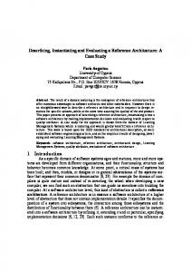
The interaction of two systems can be described by the systems themselves and a third “contextual” system (which is referred to as context) which denotes how/if the interacting systems are transformed after their interaction. The notions of schemata and transformation function are used in [1] to describe the interaction. Each system comprises of three parts, two schemata and one transformation function (see Figure 1). The function consists of an instruction from the SC instruction set (more advanced SC implementations may allow a transformation function to comprise multiple instructions). Both systems may change after an interaction, which implies circular causality (each system may affect the other). The scope here, as in nature, is an important factor. The scope of a system defines the neighbourhood (which can be other than spatial) in which the system can interact with other systems in a certain way, denoted by the context. Systems are represented as binary strings. baa0
0aab 0011
System 0011
0aab schemata1
(a)
transformation function (b)
baa0 schemata 2
Fig. 1. SC notation and systems representation: a) Graphical representation of a system in SC. b) The three elements of a system. (Reproduced with permission from [1]).
Pairs of systems always interact with a context; these systems constitute a valid triplet. The schemata of the context provide templates for the operand systems to match in order to interact, provided that all three systems belong in the same scope. Thus all computations in SC involve: • finding valid triplets (context and two matching systems in a shared scope) and • updating the two systems according to the transformation function in the context. Full details on SC are provided in [1, 2]. 2.2 Prior SC Implementations In [1], Bentley, along with introducing SC, provided a corresponding virtual computer architecture and its first implementation. This prototype included a basic instruction set, an assembly language, a compiler and resulting machine code. However the implementation was merely a simulation of a systemic computer, although it was a satisfactory proof-of-concept. The second implementation (SCoPE) [2] provides a complete SC platform (language, compiler, virtual machine and visualization tools) which is also an SC simulation, but it is based on a high-level SC language. It is fully programmable and more flexible than the original one. The transformation function set, the string
1004
C. Sakellariou, P. J. Bentley
length and the alphabet can be customized by the user for each model simulation in SCoPE. This flexibility comes in expense of execution speed. In [3], another PC-based implementation is presented, utilizing the inherent parallelism of graphics processors (GPUs) with considerable gains in terms of speed compared to previous attempts. The performance improvement is justified since this is the first implementation with a hardware constituent (GPU cores) and the first step towards a real systemic computer. GPUs are well suited for applications with numerous threads running in parallel over a set of shared data. In [3], the shared data are the systems. 3 THE PROPOSED SC HARDWARE ARCHITECTURE HAoS attempts to satisfy the basic SC requirements, taking into consideration the requirements of a practical implementation: programmability, design friendliness, technology maturity, I/O functionality efficiency, advanced processing features, compiler support and scalability. HAoS targets an FPGA as this option appears to be the optimal implementation platform among others based on a detailed review and analysis of the literature and available hardware platforms [5]. The conventional underlying architecture of a multi-core processor [6] is capable of just simulating SC, as mentioned in Section 2.2. Conventional network-based platforms (like computer clusters [7], peer-to-peer networks [8] and wireless sensors networks [9]) also rely on the same underlying architecture. However, a network can present characteristics like decentralized and distributed computation and parallelism while simulating asynchrony, self-organization and partial fault-tolerance. Thus, a network with FPGAs as basic building blocks could satisfy a large number of SC requirements by presenting these natural characteristics. Unconventional material (like DNA [10] or quantum [11]) platforms can also provide such characteristics but they are not mature enough yet to provide a practical implementation. The SC concept dictates that any three systems are eligible to form a valid triplet. A fully parallel implementation would generate a valid triplet of systems, in a random manner, for all contexts, in all scopes during an iteration of an SC program, while all interactions would happen instantaneously, provided that adequate parallel processing resources were available. Resource limitations forbid a practical implementation of this approach on an FPGA. It is apparent that the main two tasks that would ideally be executed in parallel are valid triplet generation and system transformation (the actual data processing). While one of the assumptions of the SC paradigm is that systems have “local knowledge”, storing the system bit representation and the scopes it belongs to in local registers was not adopted but instead, the binary contents of the systems and their scopes are stored in system RAM. This approach was preferred because local knowledge is a feature that cannot be accurately mapped on on-chip logic. The contents of a system could potentially be stored on registers which do not reside on
Describing the FPGA-Based HAoS
1005
the same area of the chip instead of using a RAM. The use of a RAM in this design is justified by the fact that RAM storage volumes are greater than those provided by registers in modern FPGAs and since no further fabric would need to be consumed for address decoding logic. Moreover, only a finite number of systems can be stored on a single RAM, which defines a neighbourhood for its systems, while the total number of systems can be spread over multiple RAMs. As a result, a potential failure in one of the RAMs would leave the rest of systems of the program unaffected, providing a limited level of fault-tolerance for the single-FPGA HAoS prototype. The level of faulttolerance of our single-FPGA configuration can be improved in the applicationlevel, as shown in [12], by combining redundancy (duplicating system instances) with self-maintenance (using self-repairing systems). A multi-FPGA configuration could further improve fault-tolerance by adding redundancy in the hardware-level to address faults that cannot be handled by the application (as a hardware failure of the resources used to store the global scopetable). One of the main limitations of the software-based implementations was the way valid triplets were generated. The common strategy was to randomly select three systems (one of which acted as context) in a scope and check triplet validity after matching the operand systems with the schemata of the context. A common practice to accelerate this task was to use priority queues that either gave priority to systems that had recently interacted [1] or had not recently interacted [2]. In [3], the GPU handles this task in parallel resulting in great performance gains. The present design addresses the valid triplet generation by exploiting the inherent parallelism of a Ternary Content Addressable Memory (TCAM). While traditionally used Random Access Memories (RAMs), when provided with an address return the data stored in this address, CAMs compare their input data with the data which they store and provide all matching addresses in parallel. Moreover, TCAMs have the ability to perform ternary comparisons, meaning that both the input and stored data can include “don’t care” bits. This functionality enables a guaranteed match of systems to the schemata of the given context, provided there are such systems in the scope of the context. HAoS also uses a pseudo-random number generator to randomly identify valid triplets but this operation is not biased by previous interactions. All matching systems have the same interaction probability while, as explained above, the use of the TCAM ensures maximum matching efficiency. While future work will target parallel processing capabilities, true parallel interaction is not currently supported by HAoS, since writing to the TCAM is limited to one system at a time in order to improve its area and enable ternary comparisons (assuming that parallel interactions would require simultaneous transformation the interacting systems). A fully asynchronous design might enable the true implementation of the stochastic property, but such an implementation would require that all systems, matching and control circuitry and interconnections would be realized in combinational logic which would pose a great area requirement and increase the possibility of timing hazards.
1006
C. Sakellariou, P. J. Bentley
3.1 The SC Architecture HAoS consists of the SC core (CORE), the Control Unit (CU), the Functional Unit (FU) and a set of configuration and data registers (REG BANK) for communication with the optional CPU (see Figure 2).
CONF/DATA REGS
FPGA
CORE
CONTROL FSM
EMBEDDED CPU
CU FU CONF/DATA REGS
EXTERNAL CPU
CPU INTERFACE
PROCESSING UNITS
CONF/DATA REGS
REG BANK
Fig. 2. The SC hardware architecture
The CORE contains the optimized logic for the parallel schemata matching and the memory elements. The CU handles the execution sequence of the SC program and the communication with the optional external CPU. The REG BANK provides a control and debug interface between the CPU and the local registers of the SC sub-modules. The FU provides basic local processing functionality. A set of simple instructions is supported to avoid expensive data transfers between the REG BANK and the CPU. The prototype implementation includes only one FU, but future implementations can take advantage of the plethora of DSP processing cores which are available on the FPGA, and give the option to be used as a simple ALU each, to provide multiple parallel processing resources. It is noted that only 16-bit signed integer processing is currently supported by the HAoS prototype. The addition of a hardware floating-point unit in future implementations is under investigation. However, floating-point intermediate operations of high-level functions, if required, can be executed from the optional CPU. The CPU is provided to the system in order to make more complex high-level functions available. This functionality was available only in SCoPE [2], since the other implementations had a fixed instruction set. HAoS increases flexibility by letting the user define new instructions, when this is necessary, in an unrestricted way. The SC compiler, which preserves backwards compatibility with the compiler presented in [1], is written in C and translates SC source code in SC assembly.
Describing the FPGA-Based HAoS
1007
Apart from the extra usability, the CPU in the prototype design is used to load the SC assembly code into the memory elements of the CORE during initialization or in the case of a hardware reset. A possible enhancement is to provide the option for assembly loading through an external memory card, thus making the CPU link completely optional, depending on the high-level functionality requirements of the user. As illustrated in Figure 2, the CPU may reside either on the FPGA, with the form of a soft or hard IP embedded processor communicating with the design using a shared internal FPGA bus, or be an external conventional processor connecting to the design through a standard communication interface (see Section 5). It is noted that the functional behaviour of the communication link is simulated in this work. Since the main SC program runs on the FPGA, the CPU is used as a co-processor in HAoS. A further performance and flexibility boost can be achieved in the future if we take advantage of the reconfigurability capabilities provided by the FPGA. A set of user defined pre-synthesized hardware functions can be stored on an external memory and dynamically loaded when needed. This technique could be applied for applications that do not frequently change the function part of contexts as reconfigurability speeds are quite low and would require the use of an embedded CPU to handle the reconfiguration of a reserved area on the FPGA. 3.2 The Control Unit The CU handles the flow of the user-defined SC program. As systems can never be destroyed, the program runs indefinitely, although it halts when all systems become stable and no further interaction is possible. The main control flow for each iteration of the program can be seen in Figure 3. Upon a hardware reset, the SC assembly code is loaded into the core. For each iteration of the SC program, four consecutive steps are performed. A scope is randomly selected, and then a valid triplet of systems is randomly chosen, the selected systems are fetched from memory, they interact (the actual computation is performed) and then the outcome of the interaction (the computation results) is written back to memory (the random system selection logic is described in the next section.) At the end of each iteration, the user is granted access to pause execution in order to easily extract debug information. All the optimized low-level SC microroutines (for scope and memory manipulation) are available to the user, to ensure maximum flexibility. Various optimizations have been applied in order to improve performance. When the selected context system gives a mismatch, meaning that any of its schemata does not match a system in the scope, it is disabled and becomes an invalid context for this scope to prevent future mismatches (see Section 3.3). Moreover, once a scope is selected, if it contains fewer than three systems or no valid contexts, it also is disabled and becomes an invalid scope until a new system is added to it. If all scopes have been disabled, no further transactions can occur and the program halts.
1008
C. Sakellariou, P. J. Bentley
Hardware Reset Initialization
Get Valid Triplet
Select Valid Scope
All Systems Stable?
Y
Halt
N
Load Program
Store Triplet
Select Context in Scope
Context Found?
N
Y Transform N Compute Infinite Loop
Compare Schemata 1 Write Result
Y
Compare Schemata 2 CPU Access
Match?
Match?
N
Y
Fig. 3. SC Program control flow: HAoS enters an infinite computation loop after the SC program is loaded, which involves finding valid triplets and transforming the selected systems
3.3 The SC Core The Core is mainly responsible for the efficiency of the design due to the way it handles the task of schemata matching. Its main components are the TCAM, the random selection logic, the system memories, the scopetable memories and the system status registers, as can be seen in Figure 5. HAoS supports three types of systems (see Figure 4): • data systems, comprised of two (16-bit) schemata and a zero (32-bit) function part, • context systems, comprised of a (32-bit) function and two schemata templates (used for matching with data systems and thus occupying the size of a whole data system, 64-bits,each) and • context adapter systems which have the same structure with context systems (but each of their templates can match a data system or a context). Since all the systems have the same size, each (effective) bit in a schema of a data system is padded with three zero bits to form a 4-bit element (represented as “000b” in Figure 4 a)). The full contents of a system are stored in two separate RAMs, one of them holds the binary part while the other stores the ternary part (the “don’t care” bits).
1009
Describing the FPGA-Based HAoS (a) A Data System Data System Template 1 0 00 b
Data System Template 2 32 zero bits transformation function
16 elements/effective bits
16 elements/effective bits
4bits per element
(b) A Context / Context Adapter System System 2 Template
System 1 Template 16bits schemata1
32bits transformation function
16bits schemata2
32bits context (adapter) function
16bits schemata1
32bits transformation function
16bits schemata2
Fig. 4. HAoS systems representation
Since the function part of a system is always binary, it is not stored in the ternary RAM. The various system parts are located in the same address in all memories in order to simplify the required address-decoding logic. The global scopetable information is stored in three RAM-based structures. One of them stores the systems that belong in each scope at the corresponding to the scope address, the second stores the scopes that each system belongs to at the corresponding to the system address while the third stores a mask for all the invalid contexts in a scope. The first two structures, although effectively storing the same information, provide parallel access to two different aspects of the scopetable (systems in scope and parent scopes of a system).
RANDOM SELECTION LOGIC
TCAM
SYSTEM STATUS REGS
ISDATA
L O G I C
BINARY RAM
SCH1 MASK
COUNTONES
SCH2
SCOPES
ISCONTEXT
M U X
CONTEXTS
ISADAPTER
DIVIDER
LFSR
SCOPETABLE
SYSTEMS IN SCOPE
INVALID CONTEXTS IN SCOPE
SCOPES OF SYSTEM
TERNARY RAM
L O G I C
BITPOSSEL
L O G I C
VALID SCOPES SCOPES WITH CONTEXTS
Fig. 5. The SC Core basic building blocks
CONF/DATA REGISTERS
1010
C. Sakellariou, P. J. Bentley
The TCAM is loaded with the regions of the systems that may be compared during initialization. For data systems, the function part is always zero, so only the binary representation of their two schemata may be compared while for context systems only their function part (which is double the size of a schema) may be compared. This implies that context systems can interact with other context systems or data systems, which greatly enhances functionality since it denotes that context adapting (where context systems can interact with other systems and be changed) is supported (a feature only supported previously in the highly flexible SCoPE implementation). Context adapter systems may not interact with other systems in HAoS. The restriction of comparing only parts of a system is posed by the fact that the TCAM resource requirements scale exponentially with systems capacity (the maximum number of supported systems). Thus, by minimizing the size of the TCAM, we maximize the capacity of the prototype. However, as the systems capacity of a single FPGA device is finite, in order to enable further scalability of the HAoS architecture, future work will investigate the use of either a multi-FPGA configuration or a scalable external TCAM. The random selection logic (RSL) accepts a value presenting at bus as an input and returns the address of a randomly selected set bit. It consists of a module that counts the set bits of the bus (COUNTONES), a maximal-length Linear Feedback Shift Register (LFSR) for pseudo-random number generation, a combinational divider (which also performs integer division when required in the Transform state – see Figure 3) and a module (BITPOSSEL) that given a bus and the rank of a set bit of this bus (the position of the set bit with rank 2 is 3 in 01001 101 – when rank starts from 0 and position 0 is the rightmost one), it returns its position (combining a parallel bit count approach with a branchless selection method). A random number, provided by the LFSR, is divided by the sum of the set bits of the bus. The remainder of this division is used as the rank of the random set bit that is given to BITPOSSEL in order to identify its position. The function of the RSL (the result of the selection) is controlled by a multiplexer (MUX) which feeds the RSL with one out of five possible input data paths (see Figure 5). When we need to choose a system that matches the first schema of the context, the input bus (SCH1) is generated by combining all the matching systems (the output of the TCAM) with valid SYSTEMS IN SCOPE (which of them are valid depends on the type of the context system). The same bus is used for matching the second schema (SCH2) after masking out the selected system for SCH1 (a system may not interact with itself). When a random scope is needed, the input (SCOPES) is defined by scopes which include more than two systems and at least one of their systems is a context (which is not disabled at that time). Finally, when we need to randomly identify a context in a previously selected scope, the input of the SRL (CONTEXTS) is defined by the valid contexts of the scope (meaning that previously used contexts that resulted in a mismatch are masked out). The fifth input of the MUX serves a low-level optimization for a scopetable manipulation task.
Describing the FPGA-Based HAoS
1011
3.4 HAoS Instruction Set HAoS Instruction Set Architecture (ISA) provides an on-chip hardware-supported RISC-like set of simple functions. Furthermore, in order to enhance flexibility, this core instruction set can be further extended by both extra hardware-supported application-specific instructions or software-implemented functions. It is important to note that a HAoS instruction does not share the definition of an instruction found in a conventional ISA but rather expresses the type of transformation that systems undergo when they interact. These interactions happen in a random nonsequential manner; the execution probability of each SC interaction depends solely on the number and types of systems in the SC program. The instructions are given by the transformation function (middle) part of a system (see Figure 4). Their respective fields are explained in Table 1. In this first prototype HAoS implementation, the transformation function is given by a 32-bit field. The first (LSB) 22 bits give the function identifier, the next bit enables the hardware-supported escaping functionality (to be explained later) which can be executed in parallel with any instruction except the CAPTURE instructions (also to be explained later), the next 8 bits are reserved to be used in a later implementation as variable parts of the instruction while the MSB enables the NOT functionality which reverses the matching requirement of an instruction (when enabled, the systems that do not match the provided schemata are selected). Bits Range 21:0 22 30:23 31
Meaning Function Identifier If Set Then: system also escapes from parent scope Reserved (variable part) If Set Then: the matching requirement is reversed Table 1. HAoS instruction fields
The prototype implementation of HAoS supports the instruction set given in Table 2. It is noted that this is a draft instruction set, as more instructions will be supported in the future. Table 2 comprises three sections: the SC Core hardware instructions which are supported natively from HAoS Function Unit, SC Extra instructions, which are also implemented on-chip but can be application-specific or realized outside the fixed FU (e.g. on a dynamically reconfigurable fabric or a set of DSP blocks) and software-based instructions implemented on the (on-chip or off-chip) CPU (these instructions are defined to have an opcode above a predetermined threshold in order to simplify HAoS control logic). For each instruction, its mnemonic (codename), opcode (in hexadecimal notation), a short description of the interaction they represent based on the Context Adapter Flag (discussed below) and its operation (their effect on the state, data and scope of the interacting systems) are given in the respective columns of Table 2. The Multiply instruction, for example, has MULT as a mnemonic, its opcode is 0x00000003 while schema 2 of system 1
1012
C. Sakellariou, P. J. Bentley
(sys1.sch2) gets the product of the multiplication of the schemata 2 of both systems (sys1.sch2 ∗ sys2.sch2 ) while schema 2 of system 2 is set to 1 (sys2.sch2 = 1). Various systems parts are altered after an interaction according to the Operation column. For some instructions there is the option to define a different type of interaction depending on the type of the two interacting systems. This option is controlled by the Context Adapter Flag (CAF). The CAF is a 2-bit field which states the type (data or context) of the interacting systems. Each bit corresponds to one of the system templates of a context adapter system (see Figure 4 b)). The LSB corresponds to template 1 while the MSB corresponds to template 2. A set bit in the CAF implies a context system template while a zero bit implies a data system template. Thus, a context system is essentially a context adapter system with both its system templates representing data systems (CAF = 00). When CAF is 01 or 10, the context adapter system is in mixed mode with a data system interacting with a context system and vice versa respectively, while when CAF is 11 two context systems interact. Two instructions are SC-specific and perform scopetable manipulation meaning that they alter the relationship or membership [1] of one system to another. These two instructions are ESCAPE and CAPTURE and are both optimized to be executed natively in HAoS. ESCAPE moves the escaping system (which, by convention, is the system that matches template 1) one level up in the membership hierarchy by removing it from its parent scope (which is the active scope for the interaction) and then inserts it to all the scopes that the parent scope belongs to (or parent scopes of the parent scope or in short the grandparents). The grandparents are conveniently provided in parallel (as a bus of length equal to the maximum number of scopes with set bits at the positions of the grandparents), as a part of the scopetable (SCOPES OF SYSTEM – see Figure 5). The ESCAPE task is further optimized by avoiding looping through all the possible scopes to identify the grandparents but rather only the positions of set bits are selected (using BITPOSSEL – see Section 3.3) resulting in great performance gain. The CAPTURE instruction, as the name implies, is the reverse ESCAPE task where the captured system is removed from its parent scope and added in the scope of the capturing systems which are selected based on matching template 2 of the CAPTURE system. A less efficient software implementation of the scopetable manipulation tasks is also provided to the user as an option (see Table 2). 4 TESTING AND EVALUATION Before the final design is implemented and tested in silicon, it is possible to verify its functional behaviour and assess its performance by using standard industry EDA tools. We intend to implement HAoS on the Xilinx ML605 evaluation board. Our prototype architecture, which supports a maximum number of 64 systems, is described in VHDL (7K lines of code) and synthesized targeting the on-board Virtex-6 LX240T FPGA device by using the Xilinx ISE v13.1 design suite. The
1013
Describing the FPGA-Based HAoS
Mnemonic
Code(hex) Short Description
SC Core HW Functions NOP 0000000F ESCAPE
0040000F
ADD
00000001
SUBTRACT
00000002
MULT
00000003
DIV
00000004
MOD
00000005
ISZERO
00000006
AND
00000007
OR
00000008
XOR
00000009
No Interaction System escapes from parent scope to all scopes the parent scope belongs to Add schematas of interacting systems Subtract schematas of interacting systems Multiply schematas of interacting systems Divide schematas of interacting systems Modulo of schematas of interacting systems Check if schemata of system is zero AND schematas of interacting systems OR schematas of interacting systems XOR schematas of interacting systems
COPY
0000000A
Copy parts of interacting systems
ZERO
0000000B
Zero parts of interacting systems
CAPTURE
0000000C
System is removed from parent scope & captured to capturing scope
Context Adapter Operation Flag –
–
–
Scopetable manipulation
01 01 01
sys1.sch2 = sys1.sch2 + sys2.sch2; sys2.sch2 = 0; sys1.sch2 = sys1.sch2 − sys2.sch2; sys2.sch2 = 0; sys1.sch2 = sys1.sch2 ∗ sys2.sch2; sys2.sch2 = 1; sys1.sch2 = sys1.sch2/sys2.sch2; sys2.sch2 = 1; sys1.sch2 = sys1.sch2 % sys2.sch2; sys2.sch2 = 1; if sys1.sch2 = 0 ⇒ SET sys1.sch1[schematasize-1] sys1.sch2 = sys1.sch2 AND sys2.sch2; sys2.sch2 = sys1.sch2 AND sys2.sch2; sys1.sch2 = sys1.sch2 OR sys2.sch2; sys2.sch2 = sys1.sch2 OR sys2.sch2; sys1.sch2 = sys1.sch2 XOR sys2.sch2; sys2.sch2 = sys1.sch2 XOR sys2.sch2; sys1.sch1 = sys2.sch1; sys1.sch2 = sys2.sch2; sys1.function = (sys2.sch2,sys2.sch1); sys1.function = (sys2.sch2,sys2.sch1); sys1.function = sys2.function; sys1.sch1 = 0; sys1.sch2 = 0; sys2.sch1 = 0; sys2.sch2 = 0; sys1.sch1 = 0; sys1.sch2 = 0; sys1.sch1 = 0; sys1.sch2 = 0; sys1.function = 0; sys2.function = 0;
–
Scopetable manipulation
– – – – – – – – – 00 01 10 11 00
SC Extra HW Functions Add schematas – & exchange Add schematas but keep the ADDuc2 00000012 – second unchanged SC Example CPU Functions (Above SC SW THRESHOLD=512) Software emulation of XESCAPE 00000200 – ESCAPE task Software emulation of XCAPTURE 00000201 – CAPTURE task PRINT 00000202 Print system to stdout – POWER 00000203 Exponentiation – ROOT 00000204 Arithmetic root – Knapsack Problem KNAPSACK* 00000280 – Related Functions ADDxc
00000011
sys1.sch2 = sys1.sch2 + sys2.sch2; sys2.sch2 = sys1.sch2; sys1.sch2 = sys1.sch2 + sys2.sch2;
Scopetable manipulation Scopetable manipulation – sys1.sch2 = sys1.sch2sys2.sch2 √ sys1.sch2 = sys2.sch2 sys1.sch2 *(actual functions omitted)
Table 2. HAoS instruction set
1014
C. Sakellariou, P. J. Bentley
verification environment is written in SystemVerilog (5K lines of code) and Mentor Graphics QuestaSim is used for simulation. The simulation experiments are carried TM R on an Intel Core i7 950 CPU with 4 GB of RAM running on 32-bit Windows 7 Ultimate and an nVidia GTX 260 GPU (192 CUDA cores). Xilinx design tools provide accurate area and timing implementation statistics. Thus, we can present precise performance metrics (see Table 3) before downloading our design on the FPGA. It is noted that the prototype design currently excludes the CPU INTERFACE. The DSP block is used as a multiplier in the FU.
Occupied Slices Slice LUTs Slice Registers I/O Blocks RAMs DSP Blocks
Used 5 759 15 487 6 019 143 5 1
Available 37 680 150 720 301 440 600 416 768
% 15 10 1 23 1 1
Table 3. HAoS implementation statistics on Virtex-6 LX240T FPGA
HAoS is divided into two clock domains: the REG BANK, which is connected to the CPU interface (see Figure 2) and runs at a higher clock rate (90 MHz) in order to provide faster read/write operations to the CPU, while the rest of the design is clocked at a (6 times) slower rate. Future efforts will include pipelining HAoS in order to achieve higher operating frequencies. In order to achieve system-level functional coverage closure, a series of 25 SC programs were designed to test and stress the design in various ways. An indicative set of the simulated SC test programs is given in Table 4. It is evident that basic and advanced functionality is supported by HAoS. The most interesting test case is the genetic algorithm (GA) optimization of the binary knapsack problem (using the implementation approach in [3]) which is reproduced and simulated as being executed in HAoS. In the general knapsack problem, there are n types of items (1 to n). Each type i has an associated nonnegative value vi and weight wi . The maximum combined weight of items that can fit in the knapsack is W . The binary (or 0-1) knapsack problem also poses a restriction on the number x of copies of each type of object to zero or one. The problem is mathematically formulated as Maximize
n X i=1
vi xi where
n X
wi xi 6 W and x ∈ {0, 1} .
i=1
In order to identify the solution for the knapsack problem, a set of systems are initialized with random values. Each bit in each system represents if the corresponding item will belong to the final solution. As the size of each schema is set to 16 bits in this HAoS implementation, a total of 16 items can fit in the knapsack. Initialized systems are transforming through either binary mutation, uniform crossover or
1015
Describing the FPGA-Based HAoS Systems Description of the SC Test Program 20 Additions in 4 different scopes 20
Systems subtract-escape, multiplied & printed
36 33
Systems subtract-escape and recaptured in their initial scopes Context adapter transforms context systems Mixed-mode context adapter transforms contexts to data systems Data systems are transformed to context systems Part of schemata 1 of a context is changed
12
Fibonacci numbers generator
4
Optimized incrementing counter
58
A 16-element binary knapsack problem solver based on a genetic algorithm
24 37 41
Functions Used ADD SUBe, MULT, PRINT SUBe, CAPTURE ADD, SUBe, COPY ADD, SUB, COPY SUB, COPY, ZERO ADD, ZERO ADDxce, COPY, PRINT, CAPTURE ADDuc BINARYMUTATE, CROSSOVER, INIT, OUTPUT
Table 4. A subset of the successfully simulated SC test programs
one point crossover (explained in [3]) and the one available final solution system is updated in the end of each iteration if the derived solution yields a higher weight than the one already stored. Since [1, 3] and HAoS use the same SC source code, this test program (which has not been optimized for HAoS) is used as a preliminary performance benchmark among the available SC implementations (timing metrics are approximated for the CPU interface in this work). Experimental simulation results show that for 10 000 interactions in the 16-element knapsack problem with 58 systems, the original implementation by [1] requires 33 241.2 ms, the GPU-based solution in [3] requires 255.1 ms, while HAoS needs just 55.7 ms, outperforming [1] by a factor of 596 and [3] by a factor of 4.6 (all results are based on the average of 10 repetitions of the experiment). The expected solution is found by HAoS on average after 14.9 ms while the SC program is loaded in 2.67 ms. Timing estimates of the CPU execution times were acquired by taking the average execution time of each used function (using the high resolution hardware timers of the CPU). These estimates were fed back to the verification environment in order to achieve system-level timing. It was assumed that the CPU interface (see Figure 2) can operate at the maximum supported frequency (90 MHz).The investigation of the most efficient and practical approach for the implementation of the CPU interface is discussed in Section 5. Similar results are anticipated for the other test programs. It is also noted that HAoS outperforms prior implementations in terms of the quality of the obtained results. As seen in Table 5, the correct solution for the knapsack experiment is given for a weight of 79 and a profit of 124. Only HAoS correctly estimates the expected solution given the restricted number of interactions.
1016
C. Sakellariou, P. J. Bentley
msec (factor) Solution Found (Weight : 79, Profit: 124)
Sequential 33 241.2 (x596)
GPU 255.1 (x4.6)
HAoS 55.7 (x1)
w:73, p:87
w:75, p:69.7
w:78.7, p:123.5
Table 5. Performance comparison based on the knapsack SC program
This high level of efficiency is justified from the effective way of triplet matching and the low-level optimizations of the Control Unit (mentioned in Section 3.2). 5 HAOS-CPU COMMUNICATION INVESTIGATION As described above, the use of the CPU after the SC program is loaded is optional for the HAoS prototype and depends on processing requirements. Since HAoS onchip processing capabilities are limited by the basic instruction set in Table 2, it is safe to assume that the CPU may be useful for a wide range of practical user applications. Thus, the implementation of the communication interface between HAoS and the CPU is important in order to avoid having a communication overhead as the performance bottleneck. The main design requirements for the communication link are high throughput, low latency and user-friendliness, meaning that it should be based on a widely used interface in order to minimize user effort. Since the maximum supported clock rate of our prototype is estimated at 90 MHz on the CPU interface boundary (see Figure 2), if we assume for simplicity that only single-byte data accesses are supported, a data rate requirement of 720 Mbps is posed on the communication link in order to have full utilization. We should further consider that the selected communication interface will determine the use of either an external more powerful CPU (using a commonly used but quite slower communication protocol) or a less powerful embedded (on-chip or on-board) CPU (using a relatively faster local bus). For a more realistic performance estimate, we should not only consider the maximum performance potential of the hardware but we should combine this with the actual response times caused by the software (operating system, drivers and user application programming interface implementation). Another significant consideration is that the HAoS-CPU communication will comprise quite small packets. Typically these will be less than 10 bytes for control instructions (low-level accesses of HAoS control registers which will be frequently used by the driver and also offered as part of the API to the user to enhance accessibility) and considerably less than 100 bytes for data exchange (input and output arguments of the transform task, see Figure 3). The availability of IP cores to support these interfaces and the effort required for drivers development is also important. Finally, the selected interface should be supported by the used FPGA development board (in our case, the Xilinx ML605). The external CPU option seems more appropriate since modern CPUs run more than one order of magnitude faster than embedded ones (the Intel i7 range runs
Describing the FPGA-Based HAoS
1017
typically at frequencies of 2-3GHz while the maximum frequency for a modern onchip CPU, e.g. the Xilinx MicroBlaze, is 100–300 MHz [13]). The most commonly used communication interfaces for modern computers are USB, PCI-Express and Ethernet. All of them are mature technologies which are constantly revised to support greater bandwidths. While Hi-Speed USB (or USB 2.0) is currently the most widely adopted interface, it specifies a maximum bandwidth of 480 Mbits/s [14]. Its successor, SuperSpeed USB (or USB 3.0) specifies a maximum theoretical fullduplex communication rate of 5 Gbits/s [14]. PCI-Express, featuring a point-topoint topology with separate full-duplex byte streams (1–32 lanes) connecting the device to a root complex [15], has four revisions that gradually increase bandwidth (the theoretical maximum per lane is [15]: 250 MB/s for the older Gen1, 500 MB/s for the widely used Gen2, 1 GB/s for the more recent Gen3 and 2 GB/s for the recently announced Gen4). Gigabit Ethernet is the last option supporting 1 Gb/s (higher bandwidths are also supported for specialized network devices). The theoretical maximum bandwidth that the most recent versions of all the aforementioned interfaces provide appears to be sufficient for the HAoS-CPU data rate requirement. However, their sustained performance in a working system can be considerably less due to various software and hardware sources of overhead. A quantitative example is given in [16], where a bus mastering design (implemented on a Virtex-5 FPGA) over PCI Express is measured on a Windows system. Sustained software performance is nearly 17 times slower than the theoretical maximum for a PCI Express Gen1 x1 link, mainly due to the very slow interrupt response rate of the operating system and the fact that transaction requests wait for transaction completions. Although techniques for minimizing those overheads (use of a linked list or a circular buffer of transaction descriptors for interrupts and employing a parallel transaction handling state machine) are suggested in [16] and implemented in [17, 18], there is still an inevitable deviation from the theoretical maximum. While USB 2.0 would be the most convenient option from the viewpoint of the user, it does not satisfy our bandwidth requirement. USB 3.0 provides adequate bandwidth, but it has not yet been widely adopted, so FPGA development boards with this feature are still rare and, moreover, a USB 3.0 device IP is not offered with standard industrial design tools (while designing such a complex core would require considerable effort). An implementation of the Gigabit Ethernet approach as a PCFPGA communication interface, sending UDP datagrams over IP, is given in [19] and refined in [20]. The design leaves reliability to be implemented at the user level but combines a Look Up Table (LUT), which stores all the static fields that need to keep being resent during communication, with hardware-aware optimizations which make it more attractive than alternative reliable, but more complex, full TCP/IP implementations which require an embedded CPU [19]. However, even such a light-weight protocol suffers from a big overhead when really small packets are frequently sent. These small packets carry HAoS controlrelated information and may not be grouped together to form larger contiguous blocks (in order to provide a more flexible API to the user). Even sending minimallysized raw Ethernet packets, considering that their minimum size is 64 bytes (account-
1018
C. Sakellariou, P. J. Bentley
ing for header and framing bytes – preamble, start of frame, MAC destination and source, ethertype, frame check sequence and interfame gap), results in more than 85 % overhead for control packets (typically less than 10 bytes). While they are slightly smaller, similar protocol overheads exist for the other external communications interfaces mentioned above. PCI Express Gen1 and Gen2 specify a 20 % overhead due to their 8 b/10 b symbol encoding scheme (used for clock recovery), consume 20–28 bytes for their header and framing and also suffer from traffic, link protocol and flow control protocol overheads [21]. Due to these overheads, latency is increased while the actual throughput is decreased, thus negating the performance advantage of external interfaces for typically-sized data traffic. In order to minimize protocol overheads, the alternative is to use a local communication interface, placing the CPU on-board. While FPGA development boards that provide off-chip hard processor cores are not new, a recent trend (which is not commercially available at the time of writing) attempts to overcome overheads caused by off-chip communications by combining powerful hard CPUs and programmable logic on the same die [22]. The other option is to use an embedded soft CPU. While this approach has minimal overheads, since all communications are happening at wire speed, part of the available programmable resources is occupied by the relatively low-performance soft processor. Advantages of this approach are that the design tools provide full support on embedded design, the processor can be customized to include only the features that are required (in order to optimize speed and area) and that bare-metal applications are also supported, since an operating system is optional, depending on user requirements. Following the analysis above, the embedded soft CPU interface appears to be one of the most dominant candidates for the implementation of the HAoS-CPU communication link. It is noted that this is a recommendation, rather than a definite conclusion (considering the requirements stated in the beginning of this section and currently available technologies) and it depends on the processing requirements of the user application and the flexibility of the provided API (control packets could be potentially eliminated if all the software driver logic was mapped on hardware, effectively eliminating the API since the user would be provided with just one function (transform()) to interface to hardware). For applications that utilize heavy-weight functions, the function processing time may overrule the communication overhead, thus making an external CPU interface preferable. This can either be the latest revision of PCI Express (due to the lower overhead and higher bandwidth), if compatible hardware (motherboard, development board) is available or a custom Ethernet-based interface implementing a custom light-weight protocol and a Network Interface Card capable of supporting such a protocol or USB 3.0 (subject to availability) or a future development board featuring a high-end processor. The two options may further be combined in a “smart” system that offloads computation to the appropriate CPU depending on the required processing workload. In summary, the systemic computer is designed for highly parallel software, that resembles natural systems, e.g. neural networks, genetic algorithms or models of biological networks. For such a computer to be practical it must also support
Describing the FPGA-Based HAoS
1019
sequential operations (e.g. longer mathematical expressions) and thus needs the support of a conventional CPU. The analysis here shows that current communication protocols are largely unsuitable for the task of linking an SC hardware architecture to a CPU. There is a clear need for a more integrated solution for development purposes. An FPGA board with a high-end on-board processor may be one such suitable option in the future (extending the processing capabilities in [22]). For now an embedded soft CPU provides the ability to prototype the HAoS-CPU interface. We anticipate that this will eventually lead to an ASIC, combining HAoS and a hi-speed CPU on-chip, which will minimise the bottlenecks caused by existing technologies. 6 CONCLUSIONS In this paper, the first hardware architecture specifically designed to support Systemic Computation – HAoS – is presented. The prototype is designed to balance efficiency (taking advantage of the efficient parallel comparison capability of a TCAM) and flexibility (combining embedded processing capabilities and a CPU). Various possible communication interfaces for the HAoS-CPU link implementation are discussed, suggesting an on-chip bus to a soft embedded CPU as the optimal one for prototyping, based on available technologies at the time of writing. Early results, based on a 16-element binary knapsack problem solver using a genetic algorithm, indicate that HAoS could outperform prior implementations in terms of quality of the obtained results and performance (since it is able to solve the problem nearly 600 times faster than the sequential implementation and nearly 5 times faster than the GPU implementation). Acknowledgments This work was supported by the EPSRC Doctoral Training Centre in VEIV (University College London, UK) and Toumaz UK Limited. REFERENCES [1] Bentley, P. J.: Systemic Computation: A Model of Interacting Systems With Natural Characteristics. In: A. Adamatzky, C. Tueuscher and T. Asai (Eds.): Special issue on Emergent Computation in International Journal on Parallel, Emergent and Distributed Systems, IJPEDS, Taylor & Francis pub., Oxon, UK, Vol. 22, April 2007, No. 2, pp. 103–121. [2] Le Martelot, E.—Bentley, P. J.—Lotto, R. B.: A Systemic Computation Platform for the Modelling and Analysis of Processes with Natural Characteristics. In: Proceedings of Genetic and Evolutionary Computation Conference, GECCO 2007, ACM Press, 2007, pp. 2809–2816. [3] Rouhipour, M.—Bentley, P. J.—Shayani, H.: Systemic Computation using Graphics Processors. In: G. Tempesti, A. Tyrell and J. Miller (Eds.): Evolvable
1020
C. Sakellariou, P. J. Bentley
Systems: From Biology to Hardware, LNCS, Springer, Heidelberg, Vol. 6274, 2010, pp. 121–132. [4] Sakellariou, C.—Bentley, P. J.: Introducing the FPGA-Based Hardware Arˇ chitecture of Systemic Computation (HAoS). In: Z. Kot´ asek, J. Bouda, I. Cern´ a, L. Sekanina, T. Vojnar and D. Antoˇs (Eds.): Mathematical and Engineering Methods in Computer Science, MEMICS 2011, LNCS, Springer, Berlin/Heidelberg, Vol. 7119, 2012, pp. 179–190. [5] Sakellariou, C.: Hardware-Based Systemic Computation. Thesis (MRes), Department of Computer Science, University College London, 2010. [6] Blake, G.—Dreslinski, R. G.—Mudge, T.: A Survey of Multicore Processors. Signal Processing Magazine, IEEE, Vol. 26, 2009, pp. 26–37. [7] Marcus, E.—Stern, H.: Blueprints for High Availability: Designing Resilient Distributed Systems. John Wiley & Sons Inc., 2000. [8] Milojicic, D. S.—Kalogeraki, V.—Lukose, R.—Nagaraja, K.—Pruyne, J.—Richard, B.—Rollins, S.—Xu, Z.: Peer-to-Peer computing. Technical Report HPL-2002-57, HP Labs, 2002. [9] Akyildiz, I. F.—Vuran, M. C.: Wireless Sensor Networks. John Wiley & Sons Inc., 2010. [10] Adleman, L. M.: Computing with DNA. Scientific American, Vol. 279, 1998, pp. 34–41. [11] Kari, L.—Rozenberg, G.: The Many Facets of Natural Computing. Communications of the ACM, Vol. 51, 2008, No. 10, pp. 72–83. [12] Le Martelot, E.—Bentley, P. J.—Lotto, R. B.: Crash-Proof Systemic Computing: A Demonstration of Native Fault-Tolerance and Self-Maintenance. In: Proceedings of the Fourth IASTED International Conference on Advances in Computer Science and Technology, ACST 2008, ACTA Press, 2008, pp. 49–55. [13] MicroBlaze Soft Processor Core. Available on: http://www.xilinx.com/tools/ microblaze.htm, 2012. [14] USB Implementers Forum Specifications. Available on: developers/docs/, 2012.
http://www.usb.org/
[15] PCI Special Interest Group. Available on: http://www.pcisig.com/, 2012. [16] Bittner, R.: Bus Mastering PCI Express in an FPGA. In: Proceeding of the ACM/SIGDA international symposium on field programmable gate arrays, ACM, New York, 2009, pp. 273–276. [17] Wiltgen, J.—Ayer, J.: Bus Master DMA Performance Demonstration Reference R Solutions. Application Note 1052, Design for the Xilinx Endpoint PCI Express Xilinx, 2010. [18] PCI Express High Performance Reference Design. Available on: http://www. altera.com/support/refdesigns/ip/interface/ref-pciexpress-hp.html, 2012. [19] Alachiotis, N.—Berger, S. A.—Stamatakis, A.: Efficient PC-FPGA Communication over Gigabit Ethernet. In: 10th International Conference on Computer and Information Technology, Bradford, 2010, pp. 1727–1734.
Describing the FPGA-Based HAoS
1021
[20] Alachiotis, N.—Berger, S. A.—Stamatakis, A.: A Versatile UDP/IP based PC ↔ FPGA Communication Platform. The Exelixis Lab, Exelixis-RRDR-2010-4, TU Munich, 2011. [21] Goldhammer, A.—Ayer, J.: Understanding Performance of PCI Express Systems. White Paper 350 (v1.1), Xilinx, 2008. [22] Zynq-7000 Extensible Processing Platform Summary. User Guide 804 (v1.1), Xilinx, 2011. Christos Sakellariou received his B. Sc. degree on Physics from the Aristotle University (Greece), his M. Sc. degree on Microelectronics from University of Southampton and his M. Res. degree from University College London (UCL). He currently works towards an Engineering Doctorate degree in the Department of Computer Science at UCL. His research interests include the hardware acceleration of Natural Computing, parallel computer architectures and low-latency embedded design.
Peter J. Bentley is an Honorary Reader and Senior College Fellow at the Department of Computer Science, University College London (UCL), Collaborating Professor at the Korean Advanced Institute for Science and Technology (KAIST), Visiting Fellow at SIMTech, A*STAR, Singapore, a contributing editor for WIRED UK, a consultant and a freelance writer. He has published over 200 scientific papers and is editor of the books “Evolutionary Design by Computers”, “Creative Evolutionary Systems” and “On Growth, Form and Computers”, and author of “The Ph. D. Application Handbook” and the popular science books “Digital Biology”, “The Book of Numbers”, “The Undercover Scientist” and the forthcoming “Digitized”.


![[PDF]-Download The Architecture of Computer Hardware, Systems ...](https://m.moam.info/img/260x300/pdf-download-the-architecture-of-computer-hardware_64786351097c474b228d23f8.jpg)
