chartered by OMG and INCOSE, may be found on their web site [4], along with the current .... [7] http://www.omg.org/technology/documents/formal/edoc.htm ...
Tools for Describing the Reference Architecture for Space Data Systems 1
Peter Shames , Takahiro Yamada
2
1
Jet Propulsion Laboratory, California Institute of Technology, Pasadena, California, U.S.A.
2
Institute of Space and Astronautical Science, Japan Aerospace Exploration Agency, Sagamihara, Japan INTRODUCTION Interoperability of space data systems is of great concern to Space Agencies because sharing or
reusing interoperable resources among multiple projects and multiple Agencies can reduce the cost of developing and operating space data systems. However, an on-going problem is that each space data system often has a different architecture and therefore the elements of one system cannot be easily used by other systems. Moreover, the method of describing the architecture is usually different from system to system and it is sometimes difficult to even describe the problems associated with interoperability among systems. To cope with this situation, the Consultative Committee for Space Data Systems (CCSDS) [1] has developed interoperable standards and various standard architectures to describe space data systems. CCSDS is an international, consensus based, space data system standards organization which has as members NASA, ESA, JAXA, and all the other major space agencies. Recognizing that there are already different architectures describing parts of space data systems, the approach taken by the CCSDS Systems Architecture Working Group (SAWG) was to generate a reference architecture that can be used as an end-toend framework to describe various architectures in a coherent way. This reference architecture is known as the Reference Architecture for Space Data Systems (RASDS). Using this reference architecture, architectures of different space data systems can be described in a standard way so that the commonality and differences among the systems can be easily understood. The next step is to develop a formal method for describing architectural information so that models of specific system architectures can be generated and manipulated using generic software tools and accessed and used by various pieces of application software. We anticipate great cost savings from describing architectures in a standard way, from using common tools to design systems, and from being able to share models describing these systems among diverse teams. OVERVIEW OF THE REFERENCE ARCHITECTURE Space data systems are complex entities, which may be viewed from various aspects. In order to describe the architecture of a space data system in an adequate way, RASDS uses multiple Views to present the architecture of a space data system, each view focusing on one aspect of the system. The Views used by RASDS are derived from the viewpoints defined in the Reference Model of Open Distributed Processing (RMODP) [2] but they are slightly modified from the RM-ODP viewpoints so that they can better represent the concerns of space data systems. The views used in RASDS range from the organizational to the physical component and from abstract representation to concrete implementations, they include: Enterprise, Connectivity, Functional, Information, and Communications.
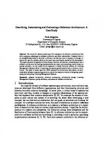
Each View is an abstraction that uses a selected set of architectural concepts and structuring rules, in order to focus on particular aspects of a space data system. Each of the Views describes the space data system in question as a set of Objects, the interactions among them, and the concerns that must be addressed for that viewpoint. An Object is an abstract model of an entity in the system. As shown in Figure 1, each Object is described with its core functions and its interfaces with other Objects. Also, a set of concerns is associated with each Object. RASDS uses the five Views that are explained in the subsequent sections to describe the architecture of space data systems. The user may decide not to use all of these five Views to describe a particular system if the system can be characterized with less than five Views. The user may also choose to combine Views using the basic concepts defined in RASDS if it is impossible to capture all the important aspects of the system with a single pre-defined View.
Management Interfaces: How objects are configured controlled, and reported upon
Object Service Interfaces: How services are requested & supplied
External Interfaces: Core functions: How external elements Decision are controlled Action Concerns: Processing Issues Resources Policies
Figure 1. Representation of Objects ENTERPRISE VIEW The motivation for the Enterprise View is that missions often have complex organizational relationships involving spacecraft, instruments, ground systems, scientists, staff, and contractors that are distributed among multiple organizations (space agencies, science institutes, companies, etc). The Enterprise View is used to address these aspects of space data systems and the relevant concerns that arise, i.e. polices, contracts, agreements, organizational interfaces and, from a security perspective, trust relationships. The Enterprise View is depicted as a set of Enterprise Objects and interactions among them, where each Object is an abstract model of an organization or facility involved in a space data system (such as a space agency, a university, a government institute, a private company, or a tracking network). A group of Enterprise Objects that plays some role in a space data system (such as a community, a committee, or a joint project) can also be an Enterprise Object.
Figure 2 shows an example of an Enterprise View for Mission A, in which Agency P builds and operates a spacecraft, Agency Q provides tracking support and Science Institute R performs scientific data analysis. CONNECTIVITY VIEW
Data Utilization Agreement
Science Institute R: performs data analysis service
Agency P: builds and operates a spacecraft
Support Service Agreement
Agency Q: provides tracking service
Figure 2. Example of Enterprise View (Mission A) The motivation for the Connectivity View is that we have system elements that are in motion through space and consequently connectivity issues associated with pointing, scheduling, long round trip light times, and low signal-to-noise ratios, all of which must be dealt with by special protocols and functionality. The Connectivity View is used to address all of these physical and performance aspects of space data systems. This is a concrete view of system elements, used in conjunction with more abstract views, such as the Functional View to show allocation of functions, and with more concrete views, such as the Communications View, to show the protocols that are required to deal with the link and environmental characteristics. The Connectivity View describes the physical elements, how they are connected, and the physical environment of a space data system. The Connectivity View is depicted as a set of Nodes and Links. A Node is an abstract model of a physical entity or component used in a space data system, which is connected to other Nodes by a Link of some sort. A Node represents a system (such as a spacecraft, a tracking system or a control system) or an individual physical element of a system (such as an instrument, a computer, or a piece of equipment). A Node may be composed of other Nodes. A Link is a physical connection between or among Nodes. A Link may be a RF link, a wired link, or a network of some kind (such as the Internet, a LAN, or a bus). Both Nodes and Links have associated behavioral properties, which include performance, location, and possibly motion. The entire set of Nodes and Links is embedded in a physical environment, which has its own properties and behaviors. Figure 3 shows Nodes and Links used for Mission A, as shown in Figure 2.
Science Spacecraft
Science Center
Space Link
Tracking Station
Ground Link
Ground Link
S/C Control Center
Figure 3. Example of Connectivity View (Mission A)
FUNCTIONAL VIEW The motivation for the Functional View is to separate functional elements and their logical interactions from the engineering concerns of where functions are housed, how they are physically connected, which protocols are used, or which technology is used to implement them. The Functional View is an abstract view used to address these aspects of space data systems. The Functional View describes the functional structure of a space data system and how functions interact with each other. The Functional View is depicted as a set of Functional Objects and the logical associations among them. A Functional Object is an abstract model of a functional entity that performs actions and generates or processes data in a space data system. An Object that only moves data is called a Communications Object and is treated in the Communications View. A Functional Object may be realized as either software or hardware. A Functional Object may be composed of other Functional Objects. A Functional Object may use services provided by other Functional Objects, provide services to other Functional Objects, or perform actions jointly with other Functional Objects. These kinds of interactions are described in the Functional View. Figure 4 shows some of the Functional Objects used for Mission A together with the logical associations between them (shown with dotted lines).
Data Acquisition
Tracking
Directive Execution
Directive Generation
Data Management
Spacecraft Analysis
Figure 4. Example of Functional View (Mission A)
Mission Planning
Science Analysis
Functional Objects actually are implemented in software or hardware and redise in physical entities (i.e., Nodes) of the system. Overlaying the Functional View on the Connectivity View of the same system will show the distribution of Functional Objects among Nodes. Such an example is shown in Figure 5, in which the Functional Objects from Figure 4 are overlaid on the Connectivity View from Figure 3. The allocation of Functional Objects to Nodes is a part of the system design trade space. The combination of these two views, and specification of the behavior of the elements, allows us to start to explore the end-to-end performance of the system. Science Spacecraft Data Acquisition
Directive Execution Science Center Science Analysis
Space Link
Tracking
Tracking Station
Data Managem ent
Ground Link
Mission Planning
Ground Link
Directive Generation
Spacecraft Analysis
S/C Control Center Figure 5. Example of Functional and Connectivity Views (Mission A)
INFORMATION VIEW The motivation for the Information View is to clarify relationships among data that are passed among the Functional elements, and to define their structures, relationships, and policies. Data are managed (that is, stored, located, accessed, and distributed) by information infrastructure elements. The Information View is used to address these aspects of space data systems. The Information View describes space data systems from the perspective of the Information Objects that are exchanged among the Functional Objects. It includes descriptions of Information Objects (their structure and syntax), information about the meaning and use of these Objects (contents and semantics), the
relationships among Objects, rules for their use and transformation, and policies on access. It also provides descriptions of the Distributed Information Infrastructure (DII) that supports the location, access, delivery, and management of these Information Objects. Finally, this View and the Functional View shows the relationship between the Information Objects and the Functional Objects that manipulate and exchange them.
Instrument Commands Directive Execution
Directive Generation Mission Directives
Observation Plans
Figure 6. Example of Information and Functional Views (Mission A) Figure 6 shows the relationship between some typical Functional Objects and the Information Objects that they exchange. This example shows a mission planning flow for Mission A, where the green objects are Functional Objects and the striped blue objects are Information Objects. COMMUNICATIONS VIEW The motivation for the Communications View is to define the layered sets of communications protocols that support communications among the functional elements. These protocols are needed to meet the requirements imposed by the connectivity and operational challenges revealed in the Connectivity View, which describes the physical configuration and operating environment of the system. The Communications View describes the engineering solutions to these space data systems challenges and is a key area of technical focus within CCSDS. The Communications View describes the mechanisms for information transfer among physical entities (i.e., Nodes) in a space data system. The Communications View is depicted as a set of Communications Objects and interactions among them. A Communications Object is an abstract model of a communications protocol that may be realized as either software or hardware. Communications Objects support information transfer between or among Functional Objects over Links (i.e., physical connections between or among Nodes). A stack of Communications Objects is usually used to support information transfer from a Functional Object to another Functional Object. In the communications stack, the topmost Communications Object directly connects to the Functional Object, and the lowest Communications Object handles the Link. The selection of Communications Objects for a Link heavily depends on the characteristics of the Functional Objects, the Nodes, the physical Link and the space environment. Therefore, it is useful to show the Functional Objects, the Nodes and the Link together with the Communications Objects in a hybrid
Science Spacecraft
Tracking Station
S/C Control Center
Directive Execution
Directive Generation
End-to-end Protocol
End-to-end Protocol (Relay)
Space Link Protocol
Space Link Protocol
Space Link
End-to-end Protocol
Gnd Link Protocol
Gnd Link Protocol
Ground Link
Figure 7. Example of Communication, Functional and Connectivity Views (Mission A) Communications View. Such an example is shown in Figure 7, in which the Communications View (Communications Objects) are shown with a simplified Functional View (Functional Objects) overlaid on the Connectivity View (Nodes and Links). METHOD AND TOOL FOR DESCRIBING ARCHITECTURES The architecture of a space data system is essentially a model of a complex system (of systems) viewed from different points of interest. The underlying element that is being created during system architecture development and design is this model. A formal method to describe these models, and agreed means for storing and exchanging these models, is also needed, and this is the focus for our current activities. Using the selected method, the architecture of space data systems will be formally described with a set of Views, where each consists of a set of Objects, their characteristics, behaviors, and interactions and the relationships among them. These formal methods will enable sharing and exchange of models of system architectures among different organizations or teams, and eliminate the need of re-generating the same information for different purposes, which happens quite frequently in actual system development. Together with the formal method for describing architectures, CCSDS plans to develop a modeling environment, based on existing commercial or academic tools, for generation and manipulation of RASDS architectures. With this approach, architectural models of a space data system will be generated by the architect or developer using the graphical user interface of the tool, and then electronically delivered to the engineering teams who use the information for building, evaluating, testing or operating the system. For example, architectural information generated by the architect can be directly fed to a generic simulator, which simulates the behavior of the system using the received information. The same model can also be fed to software tools used for detailed design or management of the system, in which the process will be to elaborate and provide added detail to the original model, rather than to re-create it at each step.
Before developing a method, CCSDS identified high-level requirements for the method and tool: 1) We need a meta-model or model language that is independent of specific tool environments and implementations; 2) We need a tool suite with a graphical interface that enables creation, manipulation, display, archiving, and versioning of meta-models, component and connector type templates, and instance models; 3) The tool shall support development of machine readable, portable architecture meta-model for RASDS; 4) The tool shall support development of instance models for specific space data systems deployments. EVALUATION OF CANDIDATE METHODS AND LANGUAGES In developing the formal method for describing architectures, CCSDS wished to utilize an existing method or language, if at all possible, so that software tools developed for that method/language could be used with minimum customization. The model or language must provide a simple and clear solution to each of the following questions: - How are the Views defined in the RASDS described? - How are the Objects defined in the RASDS Views described? - How are the properties and behavior of each of the Objects described? - How are the relationships between Objects (which may belong to different Views) described? - How are the properties of the interactions between Objects described? Using the above criteria, several candidate methods and languages were evaluated, which included UML (Unified Modeling Language) Versions 1.4 and 2.0 [3], SysML (Systems Modeling Language) [4], CIM (Common Information Model) [5], xADL (XML Architecture Description Language) [6], and EDOC (Enterprise Distributed Object Computing) [7]. A tentative agreement to use SysML as our basis was reached. SysML is being developed by a consortium called the SysML Partners by customizing UML 2.0 to support the specification, analysis, design, verification and validation of complex systems that may include hardware, software, data, personnel, procedures, and facilities. Information about this group, which is jointly chartered by OMG and INCOSE, may be found on their web site [4], along with the current specification. The SysML Partners, founded in May 2003, are collaborating to define a modeling language for systems engineering applications, called Systems Modeling Language™ (SysML™). SysML will customize and extend UML 2 to support the specification, analysis, design, verification and validation of complex systems that may include hardware, software, data, personnel, procedures, and facilities. The partners are roughly half from the major aerospace companies and half from the major UML tool vendors. This effort was motivated by the systems engineer need for a standard language for analyzing, specifying, designing, verifying and validating systems. We have lacked a broad based standard that supports general purpose systems modeling needs and satisfies a broad set of modeling requirements (behavior, structure, performance, …). The SysML approach integrates H/W and S/W disciplines, and it is scalable,
adaptable to different SE domains, and will be supported by multiple commercial tools. SysML augments the basic UML 2 abilities to describe use cases, classes, components, actions, activities, and state machines. It adds the ability to model in detail both continuous and discrete behavior and methods for modeling requirements, parametrics, and validation. MAPPING RASDS INTO SYSML SysML provides all of the capabilities to model the RASDS viewpoints and adds some additional functionality that we had not yet required. Key extensions that will prove useful are the ability to model system behavior and to model requirements and traceability to implementation. These were not considered in the RASDS work, but will be valuable in actual use of these tools in real projects. RASDS uses Viewpoints to expose different concerns of a single system whereas SysML uses specific diagrams to capture system structure, behavior, parameters and requirements. There is no simple one for one mapping from RASDS into SysML because several different SysML diagrams, focused on different object classes and relationships, may be usefully applied to any given RASDS Viewpoint. It will be necessary to extend SysML Views to define the relationships between RASDS Viewpoints and SysML Diagrams. However, SysML will support more accurate fine-grained modeling of structure, relationships and behavior than was expected of RASDS and this is a real benefit. The initial mapping of SysML diagrams onto RASDS views follows, where the primary common element is the mapping of various RASDS Objects into SysML components and collaborations. Enterprise Organizational component & collaboration diagrams Use case, interaction overview diagrams Requirements & constraints for rules, policies & agreements Connectivity Physical component, composition, collaboration & class diagrams Parametric diagram for physical link characterization Functional Logical component, collaboration & class diagrams Activity, state chart, parametric, & timing diagrams Informational Information class & parametric diagrams Communication Protocol component & collaboration diagrams State machine, sequence, activity & timing diagrams We do not have room in this paper to show the initial mappings of all of these diagrams, but our analysis, validated with the SysML Partners, is that all of the RASDS elements, relationships, views and concerns can be mapped using SysML. In order to provide the needed modeling environment we will need to construct a set of RASDS meta-classes with associated rules and to provide a library of stereotyped components that can be
assembled and customized by the end users. This is expected to be a significant but workable approach, given the anticipated availability of commercial tools that support the SysML methods. CONCLUSION This paper has briefly presented the Reference Architecture for Space Data Systems (RASDS) that is being developed by the CCSDS Systems Architecture Working Group (SAWG). The SAWG generated some sample architectures (spacecraft onboard architectures, space link architectures, cross-support architectures) using this RASDS approach, and RASDS was proven to be a powerful tool for describing and relating different space data system architectures. The European Space Agency (ESA), in a European technology harmonization of Ground Software System, is now applying the RASDS approach. RASDS will provide high level views and XASTRO [8], which is an ESA project to develop a formal method for describing systems based on xADL and UML 1.4, will be used as the method to describe the ground segment reference architecture. Many aspects of space data systems that are considered in the RASDS have not been addressed in this brief paper, but will be covered in the CCSDS Recommendation on RASDS, which will be published this year. These include security, system management, engineering details, lifecycle issues, and other aspects of designing and building real systems. CCSDS is also developing a formal method for describing architectures that facilitates generation, manipulation and sharing of architectural information electronically using software tools. SysML has been selected as the suitable candidate and mapping rules for representing RASDS with SysML are being developed under a liaison relationship between CCSDS and the SysML Partners. ACKNOWLEDGEMENTS The research described in this paper was carried out at the Jet Propulsion Laboratory, California Institute of Technology, and was sponsored by the Japan Aerospace Exploration Agency (JAXA) and the National Aeronautics and Space Administration (NASA). The authors wish to thank the members of the CCSDS System Architecture Working Group for their valuable contribution to the development of the RASDS presented in this paper. REFERENCES [1] http://www.ccsds.org [2] Information Technology - Open Distributed Processing - Reference model: Overview, International Standard, ISO/IEC 10746-1, December 1998. [3] http://www.omg.org/uml/ [4] http://www.sysml.org [5] http://www.dmtf.org/standards/cim/ [6] http://www.isr.uci.edu/projects/xarchuci/ [7] http://www.omg.org/technology/documents/formal/edoc.htm
[8] N. Lindman, et.al., XASTRO - XML Based Space Data Exchange Framework, SpaceOps 2002, October 2002.