Design a New PWM Switching Technique in Multilevel Converters Mohammed Qasim Taha
Mhd. Aymen Lpizra
University of New Haven Department of Electrical and Computer Engineering New Haven, Connecticut, United States
[email protected]
University of New Haven Department of Electrical and Computer Engineering New Haven, Connecticut, United States
[email protected]
Abstract— Designing inverter using the traditional Sinusoidal Pulse Width Modulation (SPWM) technique would require adding filter elements to minimize the output voltage signal distortion. A novel algorithm called Clipped Sinusoidal Pulse Width Modulation (CSPWM) is introduced to reduce the THD and eliminate the high order harmonic frequencies. This technique proposed using an isolation transformer to further block the DC component and improve the total harmonic THD. The proposed technique is discussed. The simulation indicated some peculiar characteristics of the proposed inverter. The analysis is successfully carried out using PSIM software Keywords— Switching Techniquge; CSPWM; converter; power conversion; Transformer Topology
multilevel
I. INTRODUCTION Inverters provide solutions to the many types of renewable energy applications. Inverter design may vary based on applications, switching frequencies, and voltages [1]. Despite the design type, inverters may have two common topologies, the push-pull and the H-Bridge. The push-pull topology is appropriate for applications where the output signal is square or modified square waveforms while the H-Bridge is more appropriate when AC sine wave output is required. Thus, multilevel inverters are modified from H-Bridge cells. It consists of a series of several connected H-Bridge inverters. Each H-Bridge inverter cell presents two levels of voltage. The AC outputs of each of the different H-Bridge inverter levels connect in a series, hence the synthesized voltage waveform is the sum of the inverter outputs. This structure is capable of reaching output voltages (Utility level voltages) using lowvoltage technology components. Improving the performance of the multilevel converters, introduced to the industry since 1975, still receive a considerable consideration by researchers. Therefore, many topologies and schemes have been proposed and studied for power utility and electric drive applications [2]. These converters/inverters are used in high and medium voltage for high power applications since they are flexible enough to synthesize an output waveform with less harmonic currents and achieve higher voltages with a limited maximum rating [3]. Typically, the inverters used for grid-tied operations are susceptible to problems of harmonic distortions. They are very
vulnerable to any electromagnetic interference such as radio equipment, requiring extra filtering. Complex and high DC link capacitors are also required since the utilized inverter is fed by one source. Additionally, the harmonic currents and high voltage (stress) change with time (dV/dt), causing a heating of the rotor core in machines and the core of the transformers due to eddy currents. Therefore, the switching frequency should be high, or a larger inductance of the output filter is required to minimize the Total Harmonic Distortion (THD). To provide guidance dealing with power quality (distortion) of power electronics, IEEE Standard 519 was introduced in 1981 and revised in 1992 and 2014. Also, IEEE std. 1547 was first drafted in 1999, and later approved in 2003 and revised in 2014 to 1547-a to provide guidance dealing with Interconnecting Distributed Resources with Electric Power Systems [4]. This standard addresses the EMI and the maximum THD level allowed for interconnection. To cope with the rising problems associated with the current carrier techniques of the inverter, this paper proposes two schemes, Clipped Sinusoidal Pulse Width Modulation (CSPWM) technique and Transformer topology, can improve the performance of multilevel converters. The proposed schemes decrease the high dV/dt and subsequently reduce harmonic currents. A new modulation technique to produce waveform with less Total Harmonic Distortion (THD) is also proposed. This multilevel PWM technique synthesizes the AC output terminal voltage with low harmonic distortion, filter requirements and energy losses [5]. Ultimately, using CSPWM, the converter produces the least amount of harmonic currents comparing with the conventional techniques. II. CSPWM TECHNIQUE Inverter output voltage is not a pure sinusoidal. It is a discrete stepped waveform that contains high order harmonics. The narrower the waveform step, fewer harmonics is generated. To generate a lower THD in the inverter output voltage wave and utilize the DC bus voltage effectively, a clipping method to the reference signal to produce new clipped form of modulation signal with PWM has been proposed. This section presents the applied clipping circuit as well as the clipped modulation signal connected to the switching circuit of the converter and the resulting output. The
978-1-5090-0799-8/16/$31.00 ©2016 IEEE
output multilevel voltage signal has been also analyzed using fast Fourier transform (FFT) algorithm to identify the spectrum of the harmonics and hence to determine THD [6]. The clipped modulation signal and hence the amplitude of the output voltage must not exceed the amplitude of the reference, because the output voltage must be equal to the reference voltage. Thus, this thesis introduces an approach that increases the slope of the signal (crest to 0 and 0 to trough and vice versa) transactions and trims the signal amplitude at the reference signal value through two steps. First, increasing the amplitude of the reference signal to a certain amount to achieve the best slope with the least number of switching pulses, which produce high order harmonics. Second, clipping the amplitude of the sinusoidal wave at the reference signal amplitude to keep the peak of the modulation signal equal to the reference signal. Calibration method has been used to determine how much the amplitude should be increased to remove the PWM pulses. After many trial and error iterations, CSPWM is implemented by increasing the modulation signal by 13% and clipping the voltage at the reference amplitude. The value of 13% has been considered after many trial-and-error iterations. Thus, for a multilevel converter of 750 Volt output, the modulation signal should be increased to be (750+0.13*750) 850 Volts, as shown in Fig. 1.
Fig. 1. The clipping circuit and a clipped sinusoidal signal Fig. 1. depicts that to create the new form of the modulation signal, the sinusoidal reference signal (or control signal that mimics the grid voltage) first should be connected to a voltage controlled source, in which the voltage can be increased by 13%. Also, this step can be implemented by connecting the reference voltage in a series to another voltage source with a magnitude of 13% of the amplitude of the reference signal amplitude. Finally, the 113% amplified voltage should be clipped with a magnitude equal to the reference signal. Fig. 2. illustrates the clipping circuit of the reference signal voltage by 13% in the new structure of the multilevel converter.
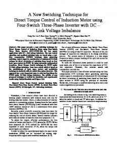
For the seven level converter, the number of H-bridge cells is 3. The peak of reference voltage is 750; hence, each DC source should be 250 Volt, which is the level’s amplitude. Each level can be synthesized by a separated DC source such as a PV module. The modulation techniques are classified according to the switching methods. Fig. 3. illustrates the output voltages for the most popular multilevel carrier-based PWM techniques and CSPWM technique. The selection of the switching frequency (2 kHz) fulfills the tradeoff of the switching losses and the electromagnetic interference [7]. V_CSPWM
V_SPWM
V_THPWM
Fig. 3. The modulation signals and techniques for the 7 level output voltage III. CSPWM RESULTS The output voltage of CSPWM technique denoted by VCSPWM in Fig. 3. And Table 1, shows the least number of switching pulses. Thus, the results of output voltage of CSPWM technique have the least number of high order harmonics. The PSIM software by Powersim Inc. was used to simulate the circuit of multilevel converter structures. The Fast Fourier Transform (FFT) analysis of PSIM indicated that the THD of the Sinusoidal PWM (SPWM) is the best among the conventional PWM techniques to be implemented. However, the output voltage of the SPWM technique (amplitude of the fundamental frequency) is 742 V, which is less than the desired value of the reference voltage of 750 V. If, the inverter output voltage is less than the voltage of the grid (reference), this prevents the inverter from exporting power from the PV system to the grid without using an additional boosting technique. The THPWM technique indicated some advantages over SPWM in terms of correcting the fundamental voltage amplitude and reaching the reference value of 750 Volt. Yet, THPWM technique produced a higher level of distortion (THD), compared with SPWM, when the inverter circuitry is a low order of the multi H-Bridge [8]. The seven-level inverter THD of these switching techniques is listed in Table 1.
Fig. 2. Cascade H-bridge seven level converter with CSPWM
TABLE I.
THD OBSERVATION FOR 7 LEVEL CONVERTER FROM PSIM
TABLE II.
SIMULATION PROGRAM
Table 1 indicates that the THD of CSPWM technique, denoted as V_CSPWM, is less than the THD values of THPWM and SPWM techniques. While THD for SPWM is 0.193 and for THPWM is 0.295, it is 0.164 for CSPWM. Therefore, this result can reduce the filtering requirements for the proposed technique. The thirteen-level converter is shown in Fig. 4. Six cells connected serially to form this structure. 13 level converter has shown a remarkable improvement of the THD for all the discussed techniques. In Fig. 5. The output waveforms are extracted to measure the THD.
THD OBSERVATION FOR 13 LEVEL CONVERTER FROM PSIM SIMULATION PROGRAM
IV.
HYBRID CSPWM AND ISOLATION TRANSFORMER TOPOLOGY
A ground isolation transformer has been known and applied to the multi-level converter to further reduce the THD. The application of the transformer suits the mid and low power applications. There are two possible configurations to connect the transformer. One is to be connected in series at the output of the converter. The other connection is to be cascaded to each H-bridge level and as a result, all H-bridges can be referenced to a common point and only one DC source is required [9].
Fig. 4: Cascade H-bridge 13-level converter with the proposed technique Fig. 6. Seven level converter with CSPWM and transformer topology This work adapted the application of such transformer winding to the proposed CSPWM technique as illustrated in Fig. 6. The waveforms of a seven-level converter with transformer topology presented in Fig. 7.
Fig. 5. 13-level CSPWM and SPWM techniques output voltages Table 2 shows that the THD of CSPWM technique, is less than the THD values of the conventional techniques. While THD for SPWM is 0.095, it is 0.084 for CSPWM. Therefore, 13 level converter combined with CSPWM reduces the filtering requirements.
Fig. 7. The 7-level waveform with the CSPWM and transformer topology
This transformer acts as filter and blocks-out the high frequency noise generated by the H-Bridge switches and nonlinear load. The PSIM calculated the THD as listed in Table 2. TABLE III. THD OBSERVATION FOR SPWM, CSPWM AND TRANSFORMER TOPOLOGY FOR 7-LEVEL CONVERTER
simulation program. The program allows the user to form the time domain and frequency domain and calculation the THD for the output voltage of the multilevel converters. Increasing the number of levels improves the performance and reduces the total harmonic distortion. Using the clipping technique further improves the result and decreases the distortion. Additionally, installing a transformer at the output of each level and connecting the secondary windings in series will have more impact on improving the output signal and reducing the distortion. REFERENCES [1]
The THD of 0.189 was generated by the SPWM and THD is 0.155 by CSPWM, and then reduced to 0.045 by adding the transformer topology. As shown in the Fig. 7, CSPWM technique has eliminated most of the high harmonics. Moreover, the transformer topology performs extra harmonics filtering to the signal. The transformer converter has important characteristics such as providing a galvanic isolation between the power source and load, which minimize the zero sequence of the ground fault current to flow from the inverter to a fault at the load side. Transformers topology is flexible and can be used for any number of levels. The ground-isolation transformer connected to multi-level inverter tends to acts as a low pass filter and blocks the DC component in the voltage waveform, thereby reducing the filtering requirements. Blocking the DC current component is needed to avoid core saturation of the machines. However, there is a setback in this topology; the maximum current drawn from the inverter is limited to the rating of the line transformers, and therefore increasing the capacity of the transformers can significantly increase cost, weight and size. These transformer converters are demanded in applications such as medical installations, which require isolation between the output neutral and power source for safety purposes [10]. V. CONCLUSION This research work has focused on modifying the multilevel inverter to reduce the THD and thus the harmonic filtering requirement. This modification has been presented in two steps: First, Modifying the switching circuit to synthesize a clipped modulation signal to reduce the THD and improve the output signal-amplitude accuracy. Second, connecting each HBridge output terminals of the multilevel converter to primary winding of a transformer, and the secondary windings connected in series. These transformers act as a harmonic suppresser and can be used as voltage controllers if needed. Multilevel converters using cascaded H-bridge topology with 3, 7 and 13-level output waveforms and separate supply DC voltage sources have been simulated and modified to reduce the THD and filtering requirements. Additionally, this technique was improved by installing transformers at the output. The technique has been investigated by the PSIM
Madhav D. Manjrekar and Thomas A. Lipo, “A hybrid multilevel inverter topology for drive applications”, IEEE APEC, Anaheim, California, pp. 523-529, Feb. 1998. [2] A. Nabae, I. Takahashi, and H. Akagi, “A new neutral-point clamped PWM inverter,” IEEE Trans. Ind. Appl., vol.17, no. 5, pp. 518–523, Sep. 1981. [3] J. Rodriguez, J. S. Lai, and F. Z. Peng, "Multilevel inverters: A survey of topologies, controls, and applications," IEEE Trans. Ind. Electron., vol. 49, no. 4, pp. 724-738, Aug. 2002. [4] IEEE Standard for Interconnecting Distributed Resources with Electric Power Systems, IEEE Std 1547-2003, 2003. [5] McGrath, B.P.; Holmes, D.G.; "Multicarrier PWM strategies for multilevel inverters," Industrial Electronics, IEEE Transactions on, vol.49, no.4, pp. 858-867, Aug 2002 [6] Chenggang Mei, Juan Carlos Balda, and William P. Waite, "Cancellation of common-mode voltages for induction motor drives using active method," IEEE Trans. Energy Conversion, Vol. 21, No. 2, pp. 380-386, Jun. 2006. [7] Mohan M Renge, Hiralal M Suryawanshi, "Three-Dimensional SpaceVector Modulation to Reduce Common-Mode Voltage for Multilevel Inverter", IEEE Trans on Ind. Electronics, vol. 57, no. 7, pp 2324-2331, July 2010. [8] J. Rodriguez, S. Bernet, B. Wu, J. O. Pontt, and S. Kouro, "Multilevel voltage-source-converter topologies for industrial medium-voltage drives," IEEE Trans. Ind. Electron., vol. 54, no. 6, pp. 2930-2945, Dec. 2007. [9] Sergio Daher, ‘Analysis, Design and Implementation of a High Efficiency Multilevel Converter for Renewable Energy Systems’, Ph. D thesis at Kassel University, 2006. [10] X. Yuan and I. Barbi, "A New Diode Clamping Multilevel Inverter," IEEE Trans. Power Electron., vol. 15,no. 4, pp. 711-718, Jul. 2000.