A DSP-BASED REGULAR SAMPLED PULSEWIDTH MODULATION (PWM) TECHNIQUE FOR A MULTILEVEL INVERTER N. A. Azli 1 and M. S. Bakar 2 1
Faculty of Electrical Engineering Universiti Teknologi Malaysia, 81310 Skudai, Johor, MALAYSIA 2
Faculty of Electrical & Electronic Engineering University College of Engineering & Technology Malaysia (KUKTEM), Locked Bag 12, 25000 Kuantan, Pahang MALAYSIA Email:
[email protected] ABSTRACT—Implementation of a regular sampled PWM technique based on a single carrier multilevel modulation strategy on a multilevel inverter using a digital signal processor (DSP) is presented in this paper. The equations representing the leading edges of the PWM pulses for the multilevel inverter are utilized in generating the gating signals for the multilevel inverter power devices using a dSPACE DS1102 controller board. Two types of the DS1102 controller board implementation are presented. The first type involves the development of MATLAB/Simulink blocks that models a PWM signal generator and used in conjunction with MATLAB/Real-Time Workshop and dSPACE/Real-Time Interface to actually generate the signals. The other type involves hand-coding (writing of a C program) with algorithms designed to generate PWM signals using the DS1102 controller board. Results based on both types of the DS1102 controller board implementation are compared and analysed. The performance of the multilevel inverter employing the later is also evaluated in terms of its output voltage waveforms and harmonic spectrums with variations in the modulation index. Index Terms—DSP, regular sampled, PWM, inverter, multilevel I. INTRODUCTION
T
HE multilevel inverter topology has gained increasing attention in recent years particularly in applications involving high voltage and power. This is mostly due to the limitations of the conventional two-level output inverters in handling high power conversion. The main feature of a multilevel inverter is its ability to reduce the voltage stress on each power device due to the utilization of multiple levels on the DC bus. This is especially important when a high DC side voltage is imposed by an application. There are several types of multilevel inverters but the one considered in this work is the modular structured multilevel inverter (MSMI).
Works that are based on the extension of the carrier-based subharmonic natural PWM strategy in traditional two-level output inverters to the multilevel inverters have been reported in literatures. In this case, the idea is to use several triangular carrier signals with only one modulating signal. Thus, this strategy is commonly known as the multicarrier modulation strategy. A single carrier multilevel modulation strategy has also been proposed as a basis to a regular sampled PWM strategy for the MSMI, with digital techniques such as a microprocessor or a digital signal processor (DSP) as its practical implementation method [1]. Further work on the regular sampled PWM strategy has been reported with the development of equations that represent the leading edges of the PWM pulses for the multilevel inverter and its implementation using a microcontroller [2]. This paper presents the results of some experimental work using a single-phase 5-level configuration of the MSMI which is an extension to the work reported in [3]. It describes the utilization of the developed equations [2] in generating the gating signals for the MSMI power devices using a dSPACE DS1102 controller board. This controller board is based on the Texas Instruments TMS320C31 floating-point DSP, which builds the main processing unit, providing fast instruction cycle time for numeric intensive algorithm. Two types of the DS1102 controller board implementation are presented. The first type involves the development of MATLAB/Simulink blocks that models the PWM signal generator and used in conjunction with MATLAB/Real-Time Workshop and dSPACE/Real-Time Interface to actually generate the signals. The other type involves hand-coding (writing of a C program) with algorithms designed to generate the PWM signals using the DS1102 controller board. Results based on both types of the DS1102 controller board implementation are compared and analysed. The performance of the MSMI employing the later is also evaluated in terms of its output voltage waveforms and harmonic spectrums with variations in the modulation index.
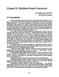
II. MODULAR STRUCTURED MULTILEVEL INVERTER (MSMI) A. Circuit Topology Fig. 1 shows a single-phase 5-level configuration of the MSMI. The MSMI is unique when compared to other types of multilevel inverters in sense that it consists of several modules that require separate DC sources. Compared to other types of multilevel inverters, the MSMI requires less number of components with no extra clamping diodes or voltage balancing capacitors that only further complicate the overall inverter operation. As can be seen from Fig. 1, each module of the MSMI has the same structure where by it is represented by a single phase full-bridge inverter. This simple modular structure not only allows practically unlimited number of levels for the MSMI by stacking up the modules but also facilitates its packaging.
S11
S21
VDC
tneg(k) is the rising edge time and represented as the timings of LOGIC 1. tpos(k) is the falling edge time and represented as the timings of LOGIC 0. k is the number of intersections of the carrier signal. Tc is the period of the carrier signal. Tm is the period of the sampled modulation signals. Ac is the amplitude of the carrier signal. Am is the amplitude of the sampled modulation signals. Bm is the cross-point at Y-axis. Bc is the cross-point at X-axis.
V-M1 S31
S41
Module 1 S12
Vo S22 V-M2
VDC S32
The PWM unipolar symmetrical regular sampled technique is developed [2] based on a single-carrier multilevel modulation strategy. The main idea is to use one triangular carrier signal with two sampled sinusoidal modulation signals. The number of sampled sinusoidal modulation signals is equal to the number of modules in the MSMI. The position of the modulation signals that change with the modulation index (mi) allows the MSMI to have a 5-level output voltage only when mi is greater than 0.5. Otherwise a 3-level MSMI output voltage is generated. In this case, the single-carrier multilevel modulation strategy works exactly as the classical unipolar PWM switching technique which gives a three level output voltage namely +VDC, 0 and -VDC for the MSMI, assuming VDC is each module’s DC source. Both the sampled modulation signals and the single carrier signal are required to develop the switching angle equations. These switching angle equations are then used to obtain the rising edge time as presented by (2) and the falling edge time as given by (3), of the PWM pulses where;
2k 1Ac Bc Tc tneg k 2 1 2 Ac Am sin k Tc Bm 2 Tm
S42
Module 2
(2)
Fig. 1. Single-phase 5-level MSMI configuration
The operation of the MSMI can be easily understood where by the output phase voltage is equal to the summation of the output voltage of the respective modules that are connected in series. The number of modules (M) which is equal to the number of DC sources required depends on the number of levels (N) of the MSMI. It is usually assumed that N is odd as this would give an integer valued M which would simplify further analysis. As an example, for an output voltage consisting of five levels which include +2VDC, +VDC, 0, -VDC and -2VDC, the number of modules needed is 2. The following equation gives the relationship between N and M. M = (N-1)/2
(1)
B. PWM Unipolar Symmetrical Regular Sampled Technique
tpos k 2k 1Tc tneg k
(3)
Based on (2) and (3) the design of the PWM signal generator blocks using MATLAB/Simulink and the algorithms to generate the PWM signal through hand-coding are developed. In both cases, the design is limited to a fixed frequency modulation ratio (mf) of 20 III. DESIGN OF THE PWM SIGNAL GENERATOR A. Development of the MATLAB/Simulink Blocks Basically, three main MATLAB/Simulink blocks are developed to represent the PWM signal generator. The functions of these blocks are:
To generate the timings of LOGIC 1 and the timings of LOGIC 0. To generate LOGIC 1 and LOGIC 0. To become an interface with the DS1102 controller board using mainly MATLAB/Real-Time Workshop (RTW) and dSPACE/Real-Time Interface (RTI) [3].
Generation of the timings for LOGIC 1 and LOGIC 0 are based on (2) and (3). Fig. 2 shows the subsystem of the MATLAB/Simulink block developed to fulfill this purpose. Block negV1(odd) is used to generate the timings of LOGIC 1 while block posV1 is used to generate the timings of LOGIC 0. Table 1 provides the related parameters that are utilized to obtain the timing values for mi = 0.4 and mi = 0.8. The timing values obtained are for the first quarter cycle of the MSMI PWM output voltage waveform. For the same value of k, the subsystem of the MATLAB/Simulink block as shown in Fig. 2 can be manipulated to generate the first half cycle of the PWM waveform. Table 2 shows the relationships between the timings of ¼ cycle, ½ cycle, ¾ cycle and one complete cycle of the PWM waveform. Based on the timing values, the pulse widths of the PWM waveform can be calculated.
where; A = timings of LOGIC 1. B = timings of LOGIC 0. The pulse widths of the PWM waveform become the inputs to the second MATLAB/Simulink block whose subsystem is shown in Fig. 3. This MATLAB/Simulink block is developed to generate LOGIC 1 and LOGIC 0 by making suitable modifications to the signal generator block from MATLAB/Simulink’s Library. The pulse widths obtained from the first MATLAB/Simulink block described earlier are converted in the form of duty cycles. Referring to Fig. 3, comparison between the values of the start_time (obtained from the MATLAB/Simulink block of Fig. 2) with the clock value will produce LOGIC 1 and LOGIC 0. Fig. 4 shows the block diagram of the interface between MATLAB/Simulink and the DS1102 controller board. Referring to Fig. 4, the DS1102ADC and the DS1102OUT blocks are interfaced with the MATLAB/Simulink (PWM) block on the input and output sides respectively. The DS1102ADC block consists of four channels that relate to the DS1102 controller board Input/Output (I/O) pins. One of the channels, in this case ADC#4 is chosen to read values from a DC power supply with voltages that can be set to vary between 0 to 10 V. These voltage values represent the modulation index of the PWM unipolar symmetrical regular sampled technique described in the previous section for the MSMI ranging typically from 0 to 1. The DS1102OUT block actually represents a 16 bit digital output whose channels that also relate to the DS1102 controller board I/O pins can be chosen to generate the PWM signals for each of the MSMI module online, in real time. However, before the signals can be generated, the MATLAB/Simulink Solver and RTW simulation parameters have to be properly set.
Fig. 2. Subsystem of the MATLAB/Simulink block to generate the timings of LOGIC 1 and LOGIC 0 TABLE 1 RELATED PARAMETERS TO GENERATE THE TIMINGS OF LOGIC 1 AND LOGIC 0.
mi 0.4 0.4 0.8 0.8
mf 20 20 20 20
Am 0.8 0.8 1.6 1.6
Bm 0 -1 0 -1
Module 1 2 1 2
TABLE 2 RELATIONSHIPS BETWEEN THE TIMING VALUES OF THE PWM WAVEFORM tneg(k) [1/4 cycle]
tpos(k) [1/4 cycle]
tneg(k) [1/2 cycle]
tpos(k) [1/2 cycle]
tneg(k) [3/4 cycle]
tpos(k) [3/4 cycle]
tneg(k) [1 cycle]
tpos(k) [1 cycle]
A
B
0.01-A
0.01-B
0.01+A
0.01+B
0.02-A
0.02-B
Fig. 3. Subsystem of the MATLAB/Simulink block to generate LOGIC 1 and LOGIC 0.
DS1102 controller board implementation, by using an oscilloscope connected to the relevant I/O pins.
Fig. 4. Block diagram of the interface between MATLAB/Simulink block and the DS1102 controller board
(a)
B. Development of the Hand-coded C program Fig. 5 shows the algorithms used to generate the PWM signals through hand-coding.
(b)
(a)
(c) Fig. 6. PWM signals for module 1 (upper) and module 2 (lower) of the MSMI for mi = 0.4 and mf = 20 based on the results obtained from (a) simulation (b) MATLAB/RTW- dSPACE/RTI (c) Hand-coding
Fig. 7 shows the PWM signals obtained for each of the MSMI module based on simulation using MATLAB/Simulink and experimental results for mi = 0.8 and mf = 20.
(b) Fig. 5. Flowchart of the hand-coding algorithms
(a)
IV. ANALYSIS ON THE RESULTS OF THE DS1102 CONTROLLER BOARD IMPLEMENTATION A. Comparison on the Generated PWM Signals For comparison purposes, Fig. 6 shows the PWM signals obtained for each of the MSMI module based on simulation using MATLAB/Simulink and experimental results for mi = 0.4 and mf = 20. The later are shown for both types of the (b)
problems in the algorithms of the C program itself. Work is still being done to rectify this problem. Through hand-coding, the algorithms can be designed for variable mi while a smallest possible sampling time can be achieved. B. Performance of the MSMI Employing the Hand-coded Implementation of the DS1102 Controller Board
(c) Fig. 7. PWM signals for module 1 (upper) and module 2 (lower) of the MSMI for mi = 0.8, mf = 20 based on the results obtained from (a) simulation (b) MATLAB/RTW- dSPACE/RTI (c) Hand-coding
Referring to Fig. 6(b) and (c) and Fig. 7(b) and (c), the main feature that can be detected from the PWM signals generated is the missing pulses. Table 3 compares the overall performance of both types of the DS1102 controller board implementation in generating the PWM signals. TABLE 3 COMPARISON BETWEEN THE DS1102 CONTROLLER BOARD IMPLEMENTATION
Type of DS1102 controller board implementation MATLAB/RTW – dSPACE/RTI
Sampling time (s)
Missing PWM pulses
280
More
Hand-coding
10
Less
Flexibility
A low power proof-of-concept prototype of the MSMI as shown in Fig. 1 is constructed with the DC voltage supplied to each module set at VDC = 100 V. Using an external logic gates circuit, the gate signals for each of the MSMI power devices are generated from the PWM signals obtained at the selected I/O pins of the DS1102 controller board. Fig. 8 and Fig. 9 show the PWM patterns and harmonic spectrums of the simulated and experimental (based on handcoding implementation of the DS1102 controller board) MSMI output voltage for ap1 = 0.4 and 0.8 respectively. The PWM waveforms of the 5-level MSMI output voltages from both the simulation and experimental results for ap1 = 0.4 and ap1 = 0.8 show three-level waveforms and five-level waveforms respectively. These results confirm the features of the single-carrier multilevel modulation strategy as described earlier. The amplitude of the harmonics from the experimental results of Fig. 8(b) and 9(b) are given in the form of rms values. For mi = 0.4, the rms amplitude of the fundamental is 56.57 V which is approximately the same as that shown in Fig. 8(b).
Fixed mi Fixed mf Variable mi Fixed mf
Using the DS1102 controller board, which is based on the Texas Instruments TMS320C31 floating-point DSP, implementation using MATLAB/RTW – dSPACE/RTI requires less time for development as it can be expanded from the simulation blocks developed using MATLAB/Simulink. However, as can be seen from Table 3, the sampling time that can be achieved is 280 µseconds which corresponds to only a 5.04 resolution for the switching instants of the PWM signals. This results in a few missing pulses in the PWM waveform particularly those that are less than one sampling interval as observed in Fig. 6(b) and Fig. 7(b). In addition, the design of the MATLAB/Simulink blocks has to be constrained to a fixed value for mi. Otherwise, a larger sampling time will be required which will contribute to more missing pulses. Hand-coding is obviously time consuming but its worthwhile in sense that the sampling time achieved is very small, in this case only 10 µseconds which translates to 0.18 resolution for the switching instants of the PWM signals. However, the results of Fig. 6(c) and Fig. 7(c) still show some missing pulses which in this case are found to be due to some
(a)
(b) Fig. 8. Output voltage of the 5-level MSMI for mi = 0.4 based on simulation (upper) and experimental (lower) results. (a) PWM waveform (b) harmonic spectrum
For mi = 0.8, the rms amplitude of the fundamental is 113.14 V which is also approximately the same as that shown in Fig. 9(b). Some even order harmonics are detected in the harmonic spectrum of the experimental MSMI output voltage for mi = 0.8. This is most probably due to the missing pulses in the PWM waveform as seen in Fig. 9(a) in comparison to the simulation results that affects its supposing quarter-wave symmetric properties.
involves hand-coding (writing of a C program) with algorithms designed to generate the PWM signals may require more development time. However, the achievable sampling time is 10 µseconds which is adequate to ensure that all the pulses are present in the MSMI output voltage PWM waveform. Although some pulses are still missing in this case for mi = 0.8, this is not due to the effect of the sampling time but more to the problem associated with the development of the algorithms in the C program which is currently being detected for rectification. Despite the problem of the missing pulses, the experimental results have shown that the amplitude of the fundamental of the MSMI output voltage are not greatly affected as the values obtained are approximately the same as the expected values according to the theory, as pointed out earlier.
REFERENCES [1].
(a) [2].
[3]
[4].
(b)
[5]
Fig. 9. Output voltage of the 5-level MSMI for mi = 0.8 based on simulation (upper) and experimental (lower) results. (a) PWM waveform (b) harmonic spectrum
[6] V. CONCLUSIONS [7] Two types of the DS1102 controller board based on the Texas Instruments TMS320C31 floating-point DSP implementation of the regular sampled PWM technique for an MSMI have been presented. The first type that involves the development of MATLAB/Simulink blocks that models a PWM signal generator and used in conjunction with MATLAB/Real-Time Workshop and dSPACE/Real-Time Interface to generate the signals are found to be less time consuming. However, the achievable sampling time is too big (280 µseconds) and not suitable if the best possible performance of the MSMI is expected. The other type that
[8]. [9]
N.A.Azli, A.H.M Yatim, F.M. Taha, “Regular Sampled Pulsewidth Modulation (PWM) Switching Strategies for A Modular Structured Multilevel Voltage Source Inverter (VSI),” in Proc. of the World Engineering Congress WEC’99. J.A.Aziz, “ A Digital Pulsewidth Modulation for the Modular Structured Multilevel Inverter,”. Master dissertation, ENCON Dept., UTM, 2002. M. S. Bakar and N. A. Azli “Simulation of a Regular Sampled Pulsewidth Modulation (PWM) Technique for a Multilevel Inverter” in Proc. Of the National Power and Energy Conference PECon 2003. N.A.Azli, A.H.M. Yatim, “A Modular Structured Multilevel Inverter for Fuel Cell Applications,” Jurnal Teknologi D,. pp. 1-12, June 2000. F. Z. Peng, J. Lai, J. W. McKeever and J. VanCoevering, “A multilevel voltage-source inverter with separate DC sources for static var generation,” IEEE Transactions on Industry Applications, vol. 32, no. 5, pp. 1130-1138, 1996. R. Lai and K. D. T. Ngo, “A PWM method for reduction of switching loss in a full-bridge inverter,” IEEE Transactions on Power Electronics, vol. 10, no. 3, pp. 326-332, 1995. G. Carrara, S. Gardella and M. Marchesoni., “A new multilevel PWM method: A theoretical analysis,” IEEE Transactions on Power Electronics, Vol. 7, No. 3, pp. 497-505, 1992. The Mathworks Inc. “Simulink,” Natick M. A.: Using Simulink Ver. 3, 1999. dSPACE Gmbh, “Floating-Point Controller Board,” Germany: DS1102 User’s Guide, 1996.