This article has been accepted for inclusion in a future issue of this journal. Content is final as presented, with the exception of pagination. IEEE/ASME TRANSACTIONS ON MECHATRONICS
1
Design and Characterization of a Robotized Gearbox System Based on Voice Coil Actuators for a Formula SAE Race Car Federico Baronti, Member, IEEE, Andrea Lazzeri, Student Member, IEEE, Roberto Roncella, Member, IEEE, Roberto Saletti, Member, IEEE, and Sergio Saponara
Abstract—This paper discusses the use of voice coil actuators to enhance the performance of shift-by-wire systems. This innovative purely electric actuation approach was implemented and applied to a Formula SAE race car. The result was more compact and faster than conventional solutions, which usually employ pneumatic actuators. The designed shift-by-wire system incorporates a control unit based on a digital signal processor, which runs the control algorithms developed for both gear shifting and launching the car. The system was successfully validated through laboratory and on-track tests. In addition, a comparative test with an equivalent pneumatic counterpart was carried out. This showed that an effective use of voice coil actuators enabled the upshift time to be almost halved, thus proving that these actuators are a viable solution to improving shift-by-wire system performance. Index Terms—Digital signal processing (DSP), formula SAE, robotized gearbox, voice coil actuators (VCAs), X-by-wire.
I. INTRODUCTION HE shift-by-wire approach is acknowledged as a valid solution to improve the performance and reliability of both race cars and commercial vehicles. The electronic control of gear shifting has important benefits in terms of a reduction in shift time, transmission chain efficiency, and savings in fuel consumption [1]–[3]. In fact, the conventional mechanical link from shift lever and clutch pedal to gearbox is replaced with sensors, electronic control units, and actuators, which make the gearbox robotized. This technique was even applied to the design of an intelligent bicycle transmission system [4]. Thus, shift-by-wire is as an effective application of X-by-wire, a very promising automotive technology that can also be applied to other vehicle functions, such as steering, braking, and throttle control [5]. Replacing the classic hydraulic or pneumatic actuators with electrical ones controlled by an appropriate digital signal processing (DSP) unit may lead to great improvements in all these automotive subsystems [6]. The DSP unit can also be connected
T
Manuscript received February 8, 2011; revised May 6, 2011; accepted June 27, 2011. Recommended by Technical Editor G. Schitter. The authors are with the Department of Information Engineering, University of Pisa, 56126 Pisa, Italy (e-mail:
[email protected]; andrea_lazzeri@iet. unipi.it;
[email protected];
[email protected];
[email protected]). Color versions of one or more of the figures in this paper are available online at http://ieeexplore.ieee.org. Digital Object Identifier 10.1109/TMECH.2011.2162632
to the vehicle dashboard for human–machine interfacing and, through feedback sensors, to the controlled subsystem. Steer-by-wire, brake-by-wire, and active suspension systems are much more critical than shift-by-wire systems. This is because they have a dramatic impact on vehicle behavior and thus on its safety [7], [8]. As a consequence, fault–tolerant architectures to meet the very high demanding safety requirements of these X-by-Wire applications are currently being investigated in depth [9]–[11]. On the other hand, the research focus on shift-by-wire systems is on improving their performance, given that appropriate architectures for their implementation are already available. This aim can mainly be achieved through an effective selection and control of the actuators employed [1], [5], [12]–[17]. Generally speaking, dc servomotors are the most commonly used X-by-wire actuators because they are easy to control in terms of speed, position, and torque [18]. Nevertheless, some interest has also been shown in linear electromagnetic actuators [1], [5], [12], [16], and particularly in voice coil actuators (VCAs), which are able to provide a wide range of forces (from less than 1 to 2000 N) together with very low inertia [19]–[23]. These two features make VCAs very attractive if compared with other linear electric actuators. Linear VCAs basically consist of a permanent-magnet cylindrical frame and a coaxial moving copper coil. Their working principle is based on the Lorentz force. According to the amplitude and the direction of the current flowing in the windings, the coil is subject to a coaxial force, which enables it to push or pull a mechanical load. VCAs can easily be scaled and adapted to different applications, in both industrial and scientific fields, because the force provided depends on their geometrical parameters. Thanks to their high reliability, small VCAs are commonly mounted inside cell phone cameras for autofocusing functions [24], [25], or inside hard disk drives to move head arms [26]–[28], whereas larger ones are used to move loudspeaker cones (which is where their name comes from) [29], for laboratory shock and vibration testing [30], or generally in robotics and factory automation [31]. This paper discusses the use of VCAs as actuators of a shiftby-wire system. In a case study, we robotized the gear and clutch devices of the ET1 vehicle, the first student-built Formula SAE race car [32]–[34] developed at the University of Pisa, Pisa, Italy. To this end, a dedicated electronic Gear Control Unit (GCU) was designed and implemented. To the best of our knowledge, this is the first time that this kind of actuator has been employed in a race car transmission system. In fact, the gear and clutch
1083-4435/$26.00 © 2011 IEEE
This article has been accepted for inclusion in a future issue of this journal. Content is final as presented, with the exception of pagination. 2
IEEE/ASME TRANSACTIONS ON MECHATRONICS
automation of Formula SAE vehicles is usually achieved by pneumatic actuators, which are lighter and smaller than VCAs. However, the use of VCAs—as will be shown later—may lead to several significant advantages. In fact, the complete assembly of a pneumatic system requires the use of valves, air tanks, and even compressors if an unlimited endurance is required. All these components may lead to a higher overall weight when compared to a more compact VCA-based system, which just comprises a power supply in addition to the actuators. In addition, a purely electric solution is more flexible and responsive than a pneumatic counterpart, and hence more suitable for implementing advanced control strategies, which may result in a higher performance [35]. As this is a new application of VCAs, we developed the numerical model reported in [36] to gather information on their behavior and to evaluate the control strategy for the ET1 gearbox; a system-level analysis was also carried out. This paper extends [36] by adding an in-depth description along with new data regarding the GCU architecture and its hardware and firmware implementation. This paper also presents experimental results on the VCA-based robotized gearbox system and a performance comparison test with an equivalent pneumatic counterpart, specifically designed for this purpose. This paper is organized as follows. Section II discusses the selection of the appropriate VCAs for our case study car, and various design guidelines are evaluated using our numerical model. Section III shows the architecture of the GCU, from both a hardware and a firmware point of view. Details on the actual implementation of the system are provided in Section IV. The performance results obtained during test sessions are reported and a comparison with an equivalent pneumatic counterpart is made. Finally, conclusions are drawn in Section V.
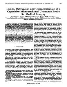
Fig. 1.
Clutch lever measurement: force versus displacement.
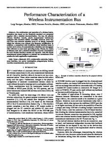
Fig. 2.
Gear lever measurement: force versus displacement, 1-N-2 sequence.
II. DESIGN The ET1 case study vehicle is equipped with an Aprilia fourstroke V-twin-cylinder RXV 550 motorcycle engine, provided with the original clutch and sequential gearbox. Thus, two VCAs are required to actuate both the clutch and gearbox levers. The first VCA is used to pull the lever of the clutch so as to disengage it. The other is mounted so that its idle position is at midstroke, and it is used to either push or pull the gear lever, so as to scan the 1-N-2-3-4-5 gear sequence, where N is neutral gear. To choose the two VCAs in the most appropriate way, the force–displacement characteristics of the two levers need to be measured. The experimental results are reported in Figs. 1 and 2, respectively. The first plot shows that a 300-N actuator with a stroke greater than 10 mm is needed to fully disengage the clutch. Instead, the second plot refers to the 1-N-2 upshifting sequence. Note that neutral is a sort of special gear that falls between first and second gears, as shown by the two 180-N peaks on the gear lever characteristic. Neutral is coded as gear 0 in the firmware of the GCU discussed in Section III-B. Neutral is shifted in at about 6 mm, and second gear at about 10 mm, which is also the displacement required by any other upshift or downshift operation. As a consequence, to completely push and
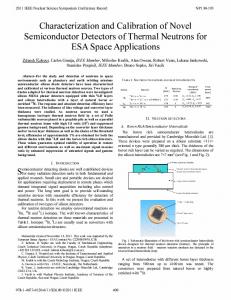
Fig. 3. Picture of the selected VCA: Accel Technologies, formerly Usas Motion, VLR0436-0250-00A.
pull the gear lever from its idle position, a 20-mm actuator is required. To simplify the mechanical implementation of the system, we adopted the same actuator for both the gear and clutch levers. The selected VCAs (Accel Technologies VLR0436-0250-00A, see Fig. 3) provide a continuous force up to 435 N with a stroke of 25 mm. As the force sensitivity is about 37.2 N/A, the maximum continuous force is obtained with a coil current of 11.7 A. The series resistance and inductance of the coil are 2.7 Ω and 4.8 mH, respectively.
This article has been accepted for inclusion in a future issue of this journal. Content is final as presented, with the exception of pagination. BARONTI et al.: DESIGN AND CHARACTERIZATION OF A ROBOTIZED GEARBOX SYSTEM BASED ON VOICE COIL
Fig. 4.
Simplified block diagram of the VCA model.
Fig. 6.
3
ET1 robotized gearbox architecture.
of the gear VCA has been set. This is the solution we adopted to implement the GCU shifting algorithms. III. GCU ARCHITECTURE
Fig. 5. Upshift and neutral selection time versus supply voltage, as derived by the model in Fig. 4.
To determine the main design guidelines for the GCU hardware and firmware, the VCA parameters, together with the actual lever force–displacement characteristics, were entered into the numerical model described in [36]. As shown by the simplified block diagram in Fig. 4, the model enables the mechanical, electrical, and thermal behavior of each actuator to be simulated. It receives the supply voltage VS and the room temperature T0 as inputs, and it outputs the actuator displacement x and speed x, ˙ as well as the coil current I and temperature T . As an example, Fig. 5 shows the time tS needed by the gear actuator to reach the shift-in position of the neutral and second gears, respectively, versus the supply voltage VS , as simulated by the model. When the second gear is shifted in, tS can be kept well below the typical 100-ms shift time of pneumatic systems [37] by simply applying a VS greater than 16 V. To disengage the clutch, a supply voltage of 21.8 V is needed to produce the 300-N force required. This voltage must carefully be controlled to let the lever gradually move around the disengagement point when the vehicle starts moving, thus avoiding wheel slip and engine shutdown. Taking all this into account, a 28 V, 350 W pulsewidth modulation (PWM) supply stage was adopted for each actuator. Consequently, both the shifting time and the clutch disengagement can be controlled by varying the related PWM duty cycle, thus giving the system good flexibility. In addition, it follows from Fig. 5 that both neutral and second gears can be selected by controlling the actuator activation time, once the supply voltage
The GCU has to implement an appropriate set of functions to enable the driver to control both the gearshift and the launch procedure by means of controls located on the steering wheel. Thus, the block diagram shown in Fig. 6 was developed and implemented on board the ET1 Formula SAE race car. The GCU is divided into a Control Section and a Power Section (see Figs. 6 and 7). The Control Section is connected to the Engine Control Unit (ECU), from which it receives information on the engine RPM. In addition, by means of a dedicated control signal (i.e., cutoff trigger in Fig. 6), the GCU triggers the ECU for the temporary suspension of the fuel injection and/or ignition, i.e. to cut off the engine. This is very useful when upshifting, as it makes clutch disengagement unnecessary. This means that the clutch VCA can be kept off during the whole upshift procedure, thus saving energy and significantly reducing the shift in time. The Control Section is also connected to the wheel speed sensors and to the driver’s interface. This interface has two flipper paddles which trigger the shifting procedures, as well as a button to select neutral. A seven-segment display and a led bar mounted on the dashboard show the currently selected gear and the engine RPM, respectively. Depending on the driver’s shift request and the vehicle’s status, the Control Section produces the appropriate PWM control signals for the two VCAs. These signals are amplified by the Power Section, and finally routed to the actuator coils. The Power Section directly drives the VCAs by means of two NMOS full H-bridge drivers (ST VNH3SP30), which are supplied by two external 12/28 V, 350 W dc/dc converters connected to the car battery. A. Hardware of the GCU The Control Section is implemented with off-the-shelf components. We opted for a DSP-based platform in order to simplify the implementation of the control algorithms with the available on-chip resources. The selected board (GAO Tek 2812EVM-I) features a 150 MHz 32 bit fixed-point Texas Instruments TMS320F2812 DSP, which embeds an advanced multichannel PWM peripheral, as well as some 16-bit timer/counters
This article has been accepted for inclusion in a future issue of this journal. Content is final as presented, with the exception of pagination. 4
Fig. 7.
IEEE/ASME TRANSACTIONS ON MECHATRONICS
GCU architecture: Control and Power Sections.
and a 12-bit analog-to-digital converter (ADC). A set of header connectors also enables a custom-designed daughter board to be plugged in and interfaced to the DSP peripherals. This is the solution we adopted to implement the Power Section, which not only has two H-bridge drivers, but also a 5 V voltage regulator to supply the Control Section itself, as well as some signalconditioning circuits to interface the different kinds of sensor to the DSP. Fig. 7 shows the final GCU architecture and the main internal DSP blocks employed to implement the system. The GPTimer2 Capture Units are used to measure the frequency of the squarewave signals coming from the wheel sensors and the ECU RPM output and hence to detect the angular speed of the wheels and the camshaft. Each Capture Unit implements an efficient frequency meter continuously running in the background, so that no computational resources of the DSP are needed for this purpose. PWM signals are obtained by the dedicated PWM State Machines. The PWM period is determined by the GPTimer1, whereas the duty cycle of each output is directly controlled by the DSP through the Compare Units. The DSP also handles two control signals for each VCA driver, which enable the H-bridge operation and set the direction of the current in the coil. Two Hall-effect current sensors (Allegro ACS756) measure the amplitude of the current flowing in each VCA coil. Their outputs are routed to the on-chip ADC, thus allowing the Control Section to get feedback from the actuators. The ADC also receives the gear sensor signal, so as to detect which gear is currently selected. This resistive-type sensor is embedded in the gearbox and is simply made up of a set of different resistances—one per gear—and a rotary switch directly operated by the gearbox. While shifting, i.e., while the rotary switch is moving, the sensor output remains open till the end of the operation. This means that open circuit will be detected if the gearbox gets stuck between two gears, thus allowing the GCU to recover by repeating the shift procedure. The ADC conversion is periodically triggered by the GPTimer4. The acquired data are low-pass filtered for denoising and are immediately made available to the main program, which implements the control algorithms. The flipper paddles and the neutral selection button, as well as the ECU connections (RPM and engine cutoff signals), are handled with General Purpose I/O (GPIO) pins. The GPIO
Fig. 8. Simplified flow diagram of the GCU main program loop. Neutral is coded as gear 0.
block provides a built-in input debouncing feature, which avoids multiple-hit detections when the driver operates the GCU controls. We decided to assign the neutral gear to a dedicated control rather than to the paddles, so that the driver cannot accidentally select it during a rapid downshift sequence. Note that the GCU and the ECU communicate by means of dedicated wired connections that use GPIO pins (see Fig. 7). In fact, the ECU of the ET1 Formula SAE race car (Walbro TDD - HPUH-1) is not equipped with a controller area network (CAN) interface. Nonetheless, the proposed GCU has a CAN interface, so that it could easily be used in a vehicle provided with a CAN communication network. Finally, as the dashboard is equipped with a serial peripheral interface, it is connected to the DSP by the multichannel buffered serial port (McBSP). B. Firmware of the GCU A simplified flow diagram of the main program loop is shown in Fig. 8. First, the inputs of the GCUs are sampled. Then, depending on the driver’s request (through flipper paddles for Upshift or Downshift, or through the button for neutral) and the vehicle’s status, i.e., the current gear and speed, one of four main procedures—namely Launch, UpShift, DownShift, and Neutral—is executed. UpShift and DownShift procedures are activated by pulling the right and the left paddle, respectively. UpShift is executed only if the gearbox is neither in fifth gear nor in neutral, coded as gear 0. Initially, the ECU is triggered for engine cutoff. Then, a 19-V voltage with an appropriate polarity is applied to the gear actuator for about 45 ms (see Fig. 5) to enable the gear lever to be fully pushed. Finally, the gear sensor signal is acquired to check if the new gear has been correctly shifted in, and if not, the procedure is retried for a programmable number of times before aborting. On the other hand, as can be seen from Fig. 8, DownShift is executed only if the first gear is not in, and if the vehicle is not standing in neutral. This procedure is exactly the same as the previous one, except that it does not trigger the ECU for the engine cutoff and it disengages the clutch before pulling the gear
This article has been accepted for inclusion in a future issue of this journal. Content is final as presented, with the exception of pagination. BARONTI et al.: DESIGN AND CHARACTERIZATION OF A ROBOTIZED GEARBOX SYSTEM BASED ON VOICE COIL
lever. Initially, the clutch VCA is powered with a 28-V voltage. The gear VCA is then actuated and the gear sensor is checked. If the correct gear has been shifted in, the clutch is reengaged by turning the VCA OFF; otherwise, a new gear actuation is retried for a programmable number of times before aborting. In the case of gear-shifting failure, an error condition is generated and signalled to the driver. The gear variable shown in the flow diagram in Fig. 8 is updated only if the gear sensor reading is valid (i.e., 0–5), so that the next shifting request can be correctly handled by the algorithm. Unlike Upshift and Downshift, the Neutral procedure is activated by a dedicated button, and is executed only if the gearbox is in the first gear. The clutch is initially disengaged, and then the gear VCA is powered at 19 V for 30 ms. As shown in Fig. 5, this is enough time to select neutral but too short to get into the second gear. At the end, the clutch is reengaged. The proposed feed-forward algorithm based on controlling the gear lever displacement by the VCA power activation time is simple, but well suited for achieving high performance in a race car application. This is because the system can be calibrated before each race. Thus, the VCA activation time can be programmed to be as short as possible keeping the likelihood of a successful shifting at a reasonable value. The shifting failure probability can then be decreased by repeating the shifting procedure, if necessary. The number of times before ending the shifting procedure with an error was set to three in the ET1 Formula SAE race car case study. Since each shifting procedure is carried out with very fast shifting times and a high probability of success, the maximum number of trials can be kept low to have a high system responsiveness in the case of gearshifting failures. The system was capable of completing more than 1000 shifting operations without aborting, as demonstrated by the on-track endurance competition discussed in Section IV, and by the many tests performed before the race. Note that as the VCA activation time during an Upshift procedure is set to 45 ms, the Upshift time is bounded by that value, which is a very significant result, as it will be shown by comparing the system with an equivalent pneumatic counterpart in the next section. Should the system be transferred from race cars to production vehicles, the control strategy needs to be made more robust against component variability, as the calibration of each car model (which has also to be repeated periodically due to component ageing) would not be feasible. In addition, increasing the VCA activation times and the number of trials before aborting would be a viable solution, as a reduction in gear-shifting speed is acceptable, but, unfortunately, is not enough to fully tackle this issue. The gear VCA activation time required to shift from first to neutral must fall between the two plotted curves in Fig. 5, at a given VCA voltage supply. Thus, shifting from first to neutral is a very critical procedure, which could permanently fail if the previous condition is no longer verified. Considering the ET1 case study, the choice to supply the gear VCA with 19 V guarantees a good separation between the two curves (the time to engage first is about twice that required for neutral), so the feed-forward control is robust enough for the requirements of a Formula SAE race car. To improve control robustness, it is possible to apply an adaptive feed-forward approach, in which
Fig. 9.
5
Simplified block diagram of the Launch procedure main loop.
the VCA activation times are adjusted according to the shift failures, which are detected by the control algorithm. For instance, if the shifting procedure from first to neutral had no effect, then the relevant activation time should be increased, whereas the VCA activation time should be decreased, if the result was to shift in the second gear. Other strategies, based on a closed control loop regulating the VCA supply voltage by the PWM driver, or combining both PWM and activation time controls, are very promising and viable without changing the hardware, with a little increase in the algorithm complexity. A more sophisticated control strategy (namely Launch procedure) is indeed applied to make the car start moving from standstill, as shown in Fig. 8. The clutch VCA current is indeed controlled by a feedback loop to smoothly release the clutch device. This prevents the engine from turning off and makes it possible to fast accelerate the vehicle. Going into more detail, the Launch Procedure is initiated while the car is stationary by disengaging the clutch and shifting in the first gear. Then, the clutch is slowly reengaged by lowering the actuator current—and thus the pulling force on the lever—in a time-linear way. The current variation is controlled by the loop reported in Fig. 9. The GCU monitors the speed v of the rear wheels. As long as v is lower than the vT1 threshold (which we set at 0.1 km/h), the slope S1 (which we set at −2.84 A/s) for the actuator current I0 is selected and integrated. Next, I0 is applied to the clutch VCA by a proportional-integrative-derivative control loop, which acts on the PWM duty cycle of the actuator driver. Thus, the clutch lever is slowly released. When the wheels start moving, i.e., v reaches vT1 , the lever is near to the engagement point. As a consequence, the slope is forced to 0, so that the current flowing in the actuator, as well as the lever position, is locked, and the car can accelerate. To make this operation easier, the driver applies light pressure to the accelerator pedal. Finally, when v is greater than vT2 (which we set at 2 km/h), S1 is selected again, and maintained until the actuator is finally switched OFF. The designed Launch Procedure proved to be reliable providing good acceleration performance on a dry track surface. The algorithm parameters (the two speed thresholds vT1 and vT2 and the slope S1 ) can be fine tuned to the different conditions of the wheels and race track, thus making the procedure very flexible and also suitable for a fast acceleration. IV. GCU IMPLEMENTATION AND RESULTS The Control Section board and the custom-made Power Section plug-in board are shown in Figs. 10 and 11, respectively. They are approximately 165 mm × 100 mm large, and are
This article has been accepted for inclusion in a future issue of this journal. Content is final as presented, with the exception of pagination. 6
Fig. 10. Control Section board (GAO Tek 2812EVM-I): 1. TMS320F2812 DSP, 2. analog input header, and 3. digital I/O header.
IEEE/ASME TRANSACTIONS ON MECHATRONICS
Fig. 12. track.
ET1 during the past Formula SAE Italy event at the Fiorano race
Fig. 11. Custom-designed Power Section daughter board: 1. VNH3SP30 clutch VCA driver, 2. VNH3SP30 gear VCA driver, and 3. power regulators for 5 V and 3.3 V logic.
mounted inside a rugged aluminum case featuring two separate multipolar automotive connectors. The first connector is used to handle the power signals, such as the 28 V and the 12 V supplies from the dc/dc converters and the battery, as well as the H-bridge outputs to drive each VCA coil. Instead, the second connector is used to handle other control signals from the driver interface or from the vehicle sensors. The final assembly was installed on board the ET1, which is shown in Fig. 12 for a previous Formula SAE Italy event at the Ferrari race track in Fiorano (Modena, Italy). On that occasion, the ET1 successfully completed the 22 km run of the endurance event, which represents a tough robustness and reliability test for all the car subsystems, particularly for the engine, the gearbox, and the proposed control and actuation electronics. Indeed, the heat required about 500 shift operations, which were all performed correctly by the designed shift-by-wire system. Before the Formula SAE event, the GCU functionality and the robotized gearbox were extensively tested both in a laboratory and during the vehicle’s tuning with the chassis dynamometer. As a significant example of the test campaign, the results for second to third gear upshift sequence are reported in the first plot of Fig. 13, which shows the activation signal of the gear VCA and the voltage provided by the gear sensor versus time. This voltage is obtained through a linear 5 V voltage divider, made up of a 2.2 kΩ pull-up resistor and the gear sensor itself. A
Fig. 13. Second to third gear upshift performance: comparison between the proposed VCA-based system and an equivalent pneumatic counterpart.
1-nF capacitor is used to filter the output of the voltage divider. When the second gear is shifted out, the gear sensor opens, and the measured voltage starts rising to 5 V with an exponential transient. Then, as soon as the third gear is in, the sensor voltage changes slope, as a falling transient starts. The time at which the voltage peak occurs identifies the shifting time, which is about 40 ms. As the VCA was powered at 19 V, this result is in good agreement with the expected performance provided by the model (see Fig. 5). Finally, the VCA-based shift-by-wire system was compared with an equivalent pneumatic system. To make a fair comparison, we replaced the gear VCA with a pneumatic actuator and performed all the tests on board the ET1. We adopted a 25 mm-diameter cylinder with the same stroke as the VCA, and a 5.3-bar regulated air supply. Thus, the achievable peak force, i.e., about 260 N, was the same provided by the VCA when powered at 19 V. Also, a fast-switching high-flow ON/OFF solenoid valve was used to control the air flow path toward the cylinder by a dedicated activation signal. A connection between the valve outlet and the cylinder was made with a short 15 cm pipe, which represents a reasonable distance between the two devices when they are mounted on board. The second plot in Fig. 13 shows that the upshift time in this case is about 74 ms, which is shorter
This article has been accepted for inclusion in a future issue of this journal. Content is final as presented, with the exception of pagination. BARONTI et al.: DESIGN AND CHARACTERIZATION OF A ROBOTIZED GEARBOX SYSTEM BASED ON VOICE COIL
TABLE 1 COMPARISON TEST SUMMARY
than the typical 100 ms value for pneumatic systems [37], but almost double that achieved with the VCA solution. This longer shifting time is mainly due to the inherent propagation delay of the air flowing from the valve to the cylinder, which can only be slightly reduced by using advanced pneumatic solutions, such as valves with a higher flow coefficient. Thus, the 46% reduction obtained using our approach could lead to a significant improvement in the overall vehicle performance, particularly in terms of acceleration time [37]. The 40 ms upshift time of our shift-bywire unit is also interesting when compared to state-of-the-art mechatronic systems, such as [14] where 76 ms are needed just to send the shift command from the lever-based man–machine interface to the gearbox. Table I summarizes the comparison between the proposed VCA-based shift-by-wire system and the pneumatic system. Regarding the hardware implementation, our VCA-based solution requires a few additional components besides the two actuators, i.e., dc/dc converters to supply the coils at a voltage higher than the standard vehicle battery voltage. The pneumatic system is more complex, as it requires directional and proportional valves or advanced control techniques [38] (to implement the linear control of the clutch), an air tank, and several pressure regulators. Nevertheless, the VCA-based system is heavier, mainly because of the permanent magnet weight. Instead, the total cost is similar for the two implementations. If we consider as a figure of merit the product of the upshift time and the total cost, the VCA-based system provides a better tradeoff between cost and performance, thanks to its faster response. Finally, note that the pneumatic system considered in Table I does not include an air compressor. In fact, in a race car application, the maximum number of shift activations during a run can be estimated in advance, and the air tank can be sized correctly so that the unnecessary weight of an on board air refilling system is saved. This does not happen in road vehicles, for which an unlimited shifting endurance must be provided. As a consequence, if we include the compressor in the pneumatic approach, the VCA solution may outperform the other system in terms of all the aspects considered. V. CONCLUSION A new implementation of a shift-by-wire system based on the use of VCAs has been described and experimentally validated. The automation of both the gear and the clutch of a Formula SAE vehicle was achieved using a DSP-based electronic GCU,
7
which directly drives each VCA through a custom-made PWM Power Section. The DSP implements both the shift and the vehicle launch algorithms. In addition, thanks to efficient firmware and to a dedicated connection with both the ECU and the speed sensors, it provides a powerful and flexible platform to develop advanced traction control algorithms, such as autoshift functions or clutch-based fast acceleration procedures. The robotized gearbox was implemented and assembled on board the ET1, the first race car built by the University of Pisa. Laboratory and on-track tests proved the full functionality of the system and showed an outstanding performance in terms of upshift time. The upshift time achieved was compared with an equivalent pneumatic solution. Test results showed a considerable shift time reduction of 46%, which allows for a significant improvement in performance, particularly during acceleration. Finally, the issues related to the application of this race car robotized gearbox to a production car have been discussed. ACKNOWLEDGMENT The authors would like to thank Dr. F. Lenzi for his valuable contribution to this work. REFERENCES [1] A. Turner, K. Ramsay, R. Clark, and D. Howe, “Direct-drive electromechanical linear actuator for shift-by-wire control of an automated transmission,” in Proc. IEEE Veh. Power Propulsion Conf., Sep. 2006, pp.1–6. [2] B. Z. Gao, H. Chen, K. Sanada, and Y. Hu, “Design of clutch-slip controller for automatic transmission using backstepping,” IEEE/ASME Trans. Mechatronics, vol. 16, no. 3, pp. 509–517, Jun. 2011. [3] J. Kim and S. B. Choi, “Design and modeling of a clutch actuator system with self-energizing mechanism,” IEEE/ASME Trans. Mechatronics, [Online]. Available: http://ieeexplore.ieee.org. DOI: 10.1109/TMECH.2010.2059034. [4] P. Tandon, A. Awasthi, B. Mishra, P. Rathore, and R. Shukla, “Design and simulation of an intelligent bicycle transmission system,” IEEE/ASME Trans. Mechatronics, vol. 16, no. 3, pp. 509–517, Jun. 2011. [5] D. Iles-Klumpner, I. Serban, and M. Risticevic, “Automotive electrical actuation technologies,” IEEE Veh. Power Propulsion Conf., Sep. 2006, pp. 1–6. [6] F. Baronti, F. Lenzi, R. Roncella, R. Saletti, and O. Di Tanna, “Electronic control of a motorcycle suspension for preload self-adjustment,” IEEE Trans. Ind. Electron., vol. 55, no. 7, pp. 2832–2837, Apr. 2008. [7] H.-R. Choi and G.-H. Choe, “A multiobjective parametric optimization for passenger-car steering actuator,” IEEE Trans. Ind. Electron., vol. 57, no. 3, pp. 900–908, Mar. 2010. [8] Y. Yamaguchi and T. Murakami, “Adaptive control for virtual steering characteristics on electric vehicle using steer-by-wire system,” IEEE Trans. Ind. Electron., vol. 56, no. 5, pp. 1585–1594, May 2009. [9] M. Naidu, S. Gopalakrishnan, and T. Nehl, “Fault-tolerant permanent magnet motor drive topologies for automotive x-by-wire systems,” IEEE Trans. Ind. Appl., vol. 46, no. 2, pp. 841–848, Mar. 2010. [10] F. Baronti, E. Petri, S. Saponara, L. Fanucci, R. Roncella, R. Saletti, P. D’Abramo, and R. Serventi, “Design and verification of hardware building blocks for high-speed and fault-tolerant in-vehicle networks,” IEEE Trans. Ind. Electron., vol. 58, no. 3, pp. 792–801, Mar. 2011. [11] S. Saponara, L. Fanucci, M. Tonarelli, and E. Petri, “Radiation tolerant spacewire router for satellite on-board networking,” IEEE Aerosp. Electron. Syst. Mag., vol. 22, no. 5, pp. 3–12, May 2007. [12] A. Turner, K. Ramsay, R. Clark, and D. Howe, “Direct-drive rotary-linear electromechanical actuation system for control of gearshifts in automated transmissions,” in Proc. IEEE Veh. Power Propulsion Conf., Sep. 2007, pp. 267–272. [13] Y.-P. Yang, J.-J. Liu, T.-J. Wang, K.-C. Kuo, and P.-E. Hsu, “An electric gearshift with ultracapacitors for the power train of an electric vehicle with a directly driven wheel motor,” IEEE Trans. Veh. Technol., vol. 56, no. 5, pp. 2421–2431, Sep. 2007.
This article has been accepted for inclusion in a future issue of this journal. Content is final as presented, with the exception of pagination. 8
[14] M. Lindner and T. Tille, “Design of highly integrated mechatronic gear selector levers for automotive shift-by-wire systems,” IEEE/ASME Trans. Mechatronics, vol. 15, no. 6, pp. 961–968, Jun. 2010. [15] N. Costantino, R. Serventi, F. Tinfena, P. D’Abramo, P. Chassard, P. Tisserand, S. Saponara, and L. Fanucci, “Design and test of an HV–CMOS intelligent power switch with integrated protections and self-diagnostic for harsh automotive applications,” IEEE Trans. Ind. Electron., vol. 58, no. 7, pp. 2715–2727, Jul. 2011. [16] I. Martins, J. Esteves, G. Marques, and F. P. da Silva, “Permanent-magnets linear actuator applicability in automotive active suspensions,” IEEE Trans. Veh. Technol., vol. 55, no. 1, pp. 86–94, Jan. 2006. [17] H. Langjord and T. A. Johansen, “Dual-mode switched control of an electropneumatic clutch actuator,” IEEE/ASME Trans. Mechatronics, vol. 15, no. 6, pp. 969–981, Dec. 2010. [18] F. Khoucha, S. Lagoun, K. Marouani, A. Kheloui, and M. El Hachemi Benbouzid, “Hybrid cascaded H-bridge multilevel-inverter induction-motordrive direct torque control for automotive applications,” IEEE Trans. Ind. Electron., vol. 57, no. 3, pp. 892–899, Mar. 2010. [19] A. Madni, J. Vuong, M. Lopez, and R. Wells, “A smart linear actuator for fuel management system,” in Proc. 5th IEEE Biannu. World Autom. Congr., 2002, vol. 14, pp. 615–624. [20] A. Babinski and T.-C. Tsao, “Acceleration feedback design for voice coil actuated direct drive,” in Proc. IEEE Amer. Control Conf., 1999, vol. 5, pp. 3713–3717. [21] M. Khandaker, H. Hong, and L. Rodrigues, “Modeling and controller design for a voice coil actuated engine valve,” in Proc. IEEE Conf. Control Appl., Aug. 2005, pp. 1234–1239. [22] W. Jones, “Easy ride: Bose corp. uses speaker technology to give cars adaptive suspension,” IEEE Spectr., vol. 42, no. 5, pp. 12–14, May 2005. [23] C. Larouci, E. Dehondt, A. Harakat, and G. Feld, “Modeling and control of the vehicle transmission system using electric actuators; integration of a clutch,” in Proc. IEEE Int. Symp. Ind. Electron., Jun.4–7, 2007, pp. 2202– 2207. [24] C.-S. Liu, P.-D. Lin, P.-H. Lin, S.-S. Ke, Y.-H. Chang, and J.-B. Horng, “Design and characterization of miniature auto-focusing voice coil motor actuator for cell phone camera applications,” IEEE Trans. Magn., vol. 45, no. 1, pp. 155–159, Jan. 2009. [25] M.-G. Song, H.-W. Baek, N.-C. Park, K.-S. Park, T. Yoon, Y.-P. Park, and S.-C. Lim, “Development of small sized actuator with compliant mechanism for optical image stabilization,” IEEE Trans. Magn., vol. 46, no. 6, pp. 2369–2372, Jun. 2010. [26] C. K. Pang, F. Lewis, S. Ge, G. Guo, B. Chen, and T. H. Lee, “Singular perturbation control for vibration rejection in HDDs using the PZT active suspension as fast subsystem observer,” IEEE Trans. Ind. Electron., vol. 54, no. 3, pp. 1375–1386, Jun. 2007. [27] R. Oboe, F. Marcassa, and G. Maiocchi, “Hard disk drive with voltagedriven voice coil motor and model-based control,” IEEE Trans. Magn., vol. 41, no. 2, pp. 784–790, Feb. 2005. [28] J. Zheng, M. Fu, Y. Wang, and C. Du, “Nonlinear tracking control for a hard disk drive dual-stage actuator system,” IEEE/ASME Trans. Mechatronics, vol. 13, no. 5, pp. 510–518, Oct. 2008. [29] P.-P. Chao, C.-W. Chiu, and Y. Hsu-Pang, “Magneto-electrodynamical modeling and design of a microspeaker used for mobile phones with considerations of diaphragm corrugation and air closures,” IEEE Trans. Magn., vol. 43, no. 6, pp. 2585–2587, Jun. 2007. [30] Y.-D. Chen, C.-C. Fuh, and P.-C. Tung, “Application of voice coil motors in active dynamic vibration absorbers,” IEEE Trans. Magn., vol. 41, no. 3, pp. 1149–1154, Mar. 2005. [31] L. Li, “Copper loss reduction of a voice-coil motor for cutting tool positioning using an auxiliary rotary motor,” IEEE Trans. Ind. Electron., vol. 46, no. 1, pp. 227–229, Feb. 1999. [32] Official Formula SAE documentation. SAE International. (2011). [Online]. Available: http://students.sae.org/competitions/formulaseries/ [33] F. Sanchez-Alejo, F. Aparicio, M. Alvarez, and E. Galindo, “The developing of personal and professional skills in automotive engineers through university competitions,” in Proc. IEEE Educ. Eng., 2010, pp. 1491–1498. [34] S. Khan and S. Sonti, “Data acquisition system for a 600cc formula SAE race car,” in Proc. IEEE Int. Conf. Veh. Electron. Safety, Nov. 2009, pp. 46–49. [35] M. Jiang, W. Chen, Y. Zhang, L. Chen, and H. Zhang, “Multi-domain modeling and simulation of clutch actuation system,” in Proc. IEEE Intell. Veh. Symp., Jun., 2009, pp. 1365–1370. [36] F. Baronti, A. Lazzeri, F. Lenzi, R. Roncella, R. Saletti, and S. Saponara, “Voice coil actuators: From model and simulation to automotive application,” in Proc. 35th IEEE Annu. Conf. Ind. Electron., Nov. 2009, pp. 1805–1810.
IEEE/ASME TRANSACTIONS ON MECHATRONICS
[37] C. H. Ping, “Shift-time limited acceleration: Final drive ratios in Formula SAE,” in Proc. SAE Motorsports Eng. Conf. Exhib., 2004, 5 pp. [38] A. Grancharova and T. A. Johansen, “Design and comparison of explicit model predictive controllers for an electropneumatic clutch actuator using on/off valves,” IEEE/ASME Trans. Mechatronics, vol. 16, no. 4, pp. 665– 673, Aug. 2011.
Federico Baronti (M’08) received the M.Sc. and Ph.D. degrees in electronic engineering from the University of Pisa, Pisa, Italy, in 2001 and 2005, respectively. He is currently a Postdoctoral Researcher in the Department of Information Engineering, University of Pisa. His research interests include the design of embedded electronic systems for biomedical, automotive, and marine applications. Other fields of interest involve the design of very large scale integration integrated circuits for high-resolution and reliable time reference generation and the development of multichannel data acquisition, and processing systems based on field-programmable gate arrays and digital signal processors.
Andrea Lazzeri (S’10) received the M.Sc. and Ph.D. degrees in electronic engineering from the University of Pisa, Pisa, Italy, in 2007 and 2011, respectively. His research interests include the design of embedded electronic systems for biomedical and automotive applications, as well as for measuring instrumentation. A particular field of interest involves the design and development of field-programmable gate array/digital signal processor-based architectures for multichannel data acquisition and real-time processing.
Roberto Roncella (M’91) was born in Viterbo, Italy, in 1959. He received the M.Sc. and Ph.D. degrees in electronic engineering from the University of Pisa, Pisa, Italy, in 1984 and 1989, respectively. He served in the Italian Navy as an Officer with technical functions. In 1990, he became a Researcher in the Department of Information Engineering, University of Pisa, where he is currently an Associate Professor in the Faculty of Engineering. His main research interests include the field of very large scale integration integrated circuits and the design of highperformance digital and analog electronic circuits for astrophysics, automotive, and biomedical applications.
This article has been accepted for inclusion in a future issue of this journal. Content is final as presented, with the exception of pagination. BARONTI et al.: DESIGN AND CHARACTERIZATION OF A ROBOTIZED GEARBOX SYSTEM BASED ON VOICE COIL
Roberto Saletti (M’10) was born in Grosseto, Italy, in 1956. He received the Dr.Ing. degree (Hons.) in electronic engineering from the University of Pisa, Pisa, Italy, in 1981. From 1983 to 1992, he was with the National Research Council as a Research Scientist. In 1987, he was with Cornell University, Ithaca, NY, as a Visiting Scientist. In 1992, he became an Associate Professor of digital system electronics in the Faculty of Engineering, University of Pisa, where, in 2001, he was appointed a Full Professor of electronics. His main research activities include the fields of design and test of high-performance integrated circuits, such as high-resolution delay-line circuits, and of electronic systems for automotive and naval applications applied in the fields of two-wheel vehicles and cruising yachts. His most recent work has been related to the development of data acquisition and measurement systems for cruising boats and innovative models of Li-Poly batteries for the electrical propulsion of vehicles.
9
Sergio Saponara received the M.Sc. (cum laude) and Ph.D. degrees in electronic engineering from the University of Pisa, Pisa, Italy, in 1999 and 2003, respectively. In 2002, he was with IMEC, Leuven, Belgium, as a Marie Curie Research Fellow. Since 2001, he collaborates with Consorzio Pisa Ricerche in Pisa. He is currently a Senior Researcher at the University of Pisa, working in the field of electronic circuits and systems. He holds the chair of “electronic systems for automotive and automation” in the Faculty of Engineering. He has coauthored more than 150 scientific publications and holds ten patents. He is also a Research Associate of Consorzio Nazionale Interuniversitario per le Telecomunicazioni (CNIT) and Istituto Nazionale di Fisica Nucleare (INFN) and served as a Guest Editor of special issues of international journals and as a Program Committee Member of international conferences.