Y Xu (IME/NUS), J Singh, C S Premachandran, K W S Chen, A K B Ratmin, N Chen (NUS), C J R Sheppard (NUS) and M Olivo (NCC), “Design and Development of a 3D Scanning MEMS OCT Probe Using a Novel SiOB Package Assembly,” Journal of Micromechanics and Microengineering. Published in Published in 18 (2008)125005 on 30 Oct 08.. Copyright 2009 IOP Publishing.
This is an author-created, un-copyedited version of an article accepted for publication in the Journal of Micromechanics and Microengineering. IOP Publishing Ltd is not responsible for any errors or omissions in this version of the manuscript or any version derived from it. The definitive publisher authenticated version is available online at doi: 10.1088/0960-1317/18/12/125005
Design and development of a 3D scanning MEMS OCT probe using a novel SiOB package assembly 1,2
1
1
1
1
2
Y Xu , J Singh , C S Premachandran , A Khairyanto , KW S Chen , N Chen ,C J R 2
3
Sheppard and M Olivo 1
Institute of Microelectronics, A*STAR (Agency for Science, Technology and Research), 11 Science Park Road, Singapore 117685
2
Division of Bioengineering, National University of Singapore, 21 Lower Kent Ridge Road, 3
Singapore 119077 National Cancer Centre, 11 Hospital Drive, Singapore 169610 E-mail:
[email protected],
[email protected] Abstract: Miniature two-axis scanning microelectromechanical systems (MEMS) micromirror integrated optical probe for three dimensional endoscopic optical coherence tomography (OCT) has been developed using a novel silicon optical bench (SiOB) packaging technique. Two-axis scanning MEMS micromirror operates with electrothermal actuation featuring low driving voltage and a maximum mechanical deflection of 17°. The optical probe was enclosed within a biocompatible, transparent, and water proof polycarbonate tube for in vivo diagnostic applications. En face and three dimensional OCT images have been performed and presented in this article.
1. Introduction
Over the years, optical coherence tomography (OCT), which uses low coherence reflectometry to detect intensity of back reflection of scattering from a sample has emerged as a unique bioimaging technique for biomedical diagnostics [1]. It has evolved from time domain systems [2, 3], to Fourier domain systems [4-6] and currently to dominating swept-source based systems [7]. The swept source systems are capable of providing three dimensional (3D) volumetric images in real time due to fast data acquisition rate up to several hundred thousand A-lines per second. Endoscopic application of OCT and the concept of “optical biopsy” were first introduced about ten years ago [8] to avoid invasive biopsy and patient trauma. This started innovations in miniaturizing OCT optics in the form of cylindrical probes. Early endeavors on miniature OCT probe implementations were focused on manipulating single mode fibers (SMF) for linear scanning in a forward-view imaging mode [9, 10] and side-view imaging mode. The general design of side-view scanning probes consists of a dynamic reflection and scanning mechanism (such as a mirror or a micro prism) mounted at the tip of the probe to manipulate the focused beam from SMF for OCT imaging. External drive mechanisms, such as a motor for circumferential scanning [11, 12] and a linear translation stage for transverse scanning [13], were used to drive a SMF but scanning speed was limited to a few Hz due to friction during movement and rigidity of the fiber. Subsequently, MEMS started playing a key role in the developments of OCT probes, which were integrated with post-objective distal scanning MEMS devices enabling high speed three dimensional imaging. A variety of MEMS devices based on electrothermal [14, 15], electrostatic [16-19], magnetic [20] and pneumatic [21] actuation mechanisms had been demonstrated in endoscopic OCT application.
1
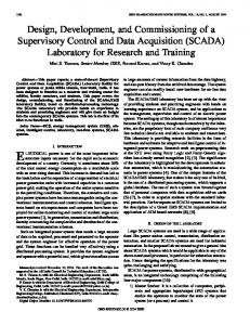
Figure 1: (A) Conventional bench top OCT configuration. (B) Conceptual depiction of miniature OCT optics.
Miniaturization of the optics and scanners in the sample arm of the OCT system is a challenge for endoscopic applications as there is a trade-off between size of the probe and the quality of the OCT images. Figure 1 illustrates the differences between the conventional bench top OCT optics with the miniature probe OCT optics. The bench top optical microscope configuration utilizes two galvo mirrors for X and Y axis scanning (Fig. 1A). As there is no limitation of the space, quality of the image can be improved by having larger scanning mirrors and larger diameter high intensity light beams. In the case of miniature optics (Fig. 1B) the diameter size of the probe restricts the overall dimensions of the micromirror / micro-prism and hence in a way constrains the overall efficiency of managing the light beam incident on the sample and scattered light from the sample. This article presents a study of the development of a MEMS OCT probe assembled using silicon optical bench (SiOB) technology. The probe is integrated with a two-axis scanning MEMS micromirror, which is developed using a novel single substrate silicon on insulator (SOI) fabrication process. Main characteristics of the mirror are low driving voltage, large mechanical deflection and high fill-in factor. The probe also consists of a gradient refractive index (GRIN) lens apart from SiOB components. The diameter of the miniature probe is about 4 mm and the length is about 25 mm. This article provides detailed characterization of the probe with En face and three dimensional OCT images demonstrating proof of concept. 2. Two-axis MEMS micromirror design, fabrication and characterization
2
Figure 2: (A) Two-axis micromirror 3D model, (B) Electrothermal actuator and spring, (C-D) Optical microscopic images of realized micromirrors and (E) A SEM micrograph of Al-Si electrothermal actuator.
The two-axis micromirror was initially developed for switching in optical communication application with the chip size of 2.5 mm x 2.5 mm and the mirror plate diameter of 400 µm. Its maximum mechanical deflection was 10° with less than 2 volts driving voltage [22]. Electrothermal actuators require very low operation voltage, which is advantageous in in-vivo biomedical applications, as low voltage would be safer in comparison to high applied voltage needed for electrostatic actuation mechanisms [25 -27]. The process scheme was refined to develop a new micromirror with reduced chip size for MEMS OCT endoscope probe imaging application [23, 24]. A three-dimensional model of the mirror is shown in Fig. 2A, which is based on electrothermal actuation mechanism and two-axis gimbal-less architecture. It consists of a high reflective gold-chromium mirror plate, four flexural springs and four electrothermal bimorph actuators, as shown in Fig. 2B. Optical microscopic images of the micromirror chips are shown in Fig. 2C and 2D. Composite beams of silicon and aluminum form bimorph electrothermal actuators. The actuation is based on the bimetallic effect due to the difference in the coefficient of thermal expansion (CTE). A close-up view of the bimorph actuator is shown in Fig. 2E. An Al layer was also used as the heater material with the thermal resistance of about 50 Ohms. The single wafer SOI substrate process which has been illustrated in Ref. 23 was based on the deep reactive ion etching (DRIE) complementary metal oxide semiconductor (CMOS) compatible fabrication. The device with a chip size of 1.5 mm x 1.5 mm had a 500 µm diameter mirror plate.
3
Figure 3: Characterization of the Al-Si bimorph actuator: (A) current versus voltage and (B) mechanical deflection/temperature versus voltage.
Characterization of the two-axis micromirror was carried out. A precision semiconductor parameter analyzer (4156C, Agilent Technologies, United States) was used for the measurements. The maximum measured mechanical deflection of 17° was obtained at an operation voltage of ~1.3 volts. We also observed that the mirror device was damaged as the voltage was increased to more than 1.5 volts. Further investigations showed that it was a mechanical failure due to excess flexural bending of the springs. The maximum current before the actuator breakdown was 24 mA (Fig. 3A). An IR camera with 20 µm resolution was used for measuring temperature as a function of voltage applied on single bimorph actuator and the data is plotted in Fig. 3B. Mechanical deflection as a function of temperature on one actuator is also shown in Fig. 3B. Maximum possible temperature was 90 °C. The radius of curvature of the mirror plate was measured to be about 30 mm. An optical surface profiler (Wyko DMEMS NT 3300, Veeco Instruments Inc., United States) was used for this test. Repeatability and reliability tests which were performed on the first 2.5 mm x 2.5 mm chip [22], showed no hysteresis. Single crystal silicon is well known for no hysteresis characteristics.
Figure 4: Frequency response of the micromirror with unipolar 1.2 volts peak-to-peak sinusoidal signal for full range swing.
In order to measure the frequency response, a unipolar 1.2 volts peak-to-peak sinusoidal signal was applied to one bimorph actuator of the micromirror. The cut off -3dB frequency was obtained to be 46 Hz as the voltage frequency was increased from 1 to 500 Hz. The corresponding thermal response time is 7.6 msec. This operation frequency is well above the required frequency of about 20Hz for our optical probe.
4
Figure 5: (A)-(D) Lissajous figures scanned by the micromirror.
Laser patterns shown in Fig. 5 were obtained by switching two adjacent thermal actuators in one quarter of the operable space. A Labview program was used to write loop structure patterns using applied voltage as X-Y points in 2D space. The repetition rate for the loops was 10 Hz. Reliability tests were not carried out specifically for the OCT probe micromirror device; however, similar thermal actuated micro mirror was tested for about 100 million cycles at 40 Hz previously [22]. Spring specifications in the current device were the same as in the previous case and therefore we can estimate that the current device was very reliable for the optical probe usage, which would be much smaller relatively. Silicon is one of the best known materials for not exhibiting hysteresis, and in our feasibility study also [23], we observed repeatable scanning along the straight line, which was crucial to consider the micromirror device for OCT optical probe. The flatness of the micromirror was measured using a WYKO surface profiler and found to be 30 mm, which caused a reduction in working distance from mirror surface to the sample. We investigated the issue and found that the cause for this curvature was use of different kinds of Cr-Au thin films on the front (sputtered) and backside (e-beam evaporated) and Cr was contributing to most of the curvature. We stripped thin films one by one and found no appreciable change in the curvature until Cr was removed. Micromirror curvature had improved to few meters once Cr was stripped off. In our future work, we will rectify this issue and would have flatter micromirror for integration in optical probe. 3. Probe design and SiOB assembly
5
Figure 6: (A) Fabrication process of lower substrate of a SiOB. (B) Side-view of SiOB assembly.
In an earlier reported work [17], a OCT probe with 5 mm diameter was realized using acrylic sheath package assembly, housing and wire bonding for electrical connection. In another design [18], a machined aluminum package with tiny screw sets was used for housing and optical alignment. In the work presented in this article, a novel SiOB precision assembly scheme has been used to reduce the diameter size of the probe and it was also useful to overcome difficulties in providing electrical connections to the micromirror at the distal end. The SiOB package assembly consists of a pair of silicon substrates, a upper substrate and a lower substrate, with assembly slots for the single mode fiber (SMF), the GRIN lens, and the micromirror. The package provides self assembly where one component alignment forces others to align as well [28]. The fabrication process for the lower substrate of SiOB is shown in Fig. 6A and the assembly process is illustrated in Fig. 6B. Silicon etching in aqueous solution of potassium hydroxide (KOH) was used to anisotropically cut the slot for the micromirror device in the 6
lower substrate and the deep reactive ion etching (DRIE) process was used to cut GRIN lens and SMF slots at 45 degrees to the micromirror slot on the upper substrate. These two processes provided for the self alignment between GRIN lens and the micromirror. Metal lines were patterned on the lower substrate to provide metal connections to the micromirror. Sloped trench formed in aqueous solution of KOH at 54.7˚ from the wafer surface due to crystallographic orientation dependent etch of silicon provided a perfect way to bring metal lines on trench slopes closer to the metal pads on the micromirror. The micromirror was manually placed in the etched trench of the lower substrate. There were five contact pads on the MEMS micromirror chip and five 200 µm size solder balls were placed between these pads and the metal lines on the lower substrate. Subsequently reflow and curing were carried out to establish rigid connection between the two. A completed bonding is shown in a SEM micrograph, Fig. 7B. The upper silicon substrate was thinned down to appropriate thickness and a 500 µm diameter SMF attached GRIN lens with 0.04 numerical aperture (NA) and 5 mm working distance (GRINTECH GmbH, Germany) was fixed in the slots of the upper substrate. The GRIN lens was aligned to lightly focus the optical beam onto the micromirror in the trench (Fig. 7A). The distance between the front surface of the GRIN lens and the center of the micromirror is 1.5 mm so that we left 3.5 mm from the actually working distance between the center of the micromirror to the focal point. The assembled SiOB probe was finally housed in a transparent polycarbonate injection molded tube (i3 Lab Pte Ltd, Singapore) of the outer diameter less than 4 mm (Fig. 7C). The side walls of the tube were 300 µm thick and they were coated with an antireflection coating to minimize loss of light. At the proximal end of the polycarbonate housing, a small printed circuit board (PCB) and 5 tiny electrical wires provided an interface for external drive circuit (not shown in Fig. 7).
7
Figure 7: (A) SiOB assembly and package, (B) SEM micrograph of assembly of a micromirror to SiOB with micro solder balls (turned 90˚ from Fig. 7A) and (C) Photo of an assembled miniature OCT probe with a one dollar coin. 4. OCT imaging experiment 4.1. Experimental setup The testing of assembled SiOB MEMS OCT probe was carried out using a commercial swept source OCT system (OCM1300SS, Thorlabs, United States). The schematic diagram of the system is shown in Fig. 8A. The swept-source OCT system incorporates a high speed frequency swept external cavity laser (SL1325-P16, Thorlabs, United States), which has a full-width at half-maximum (FWHM) bandwidth of 110 nm centered at 1325 nm and 16 kHz fast frequency sweep rate. The output of the light source was split into the sample arm and the reference arm by a broad band 50/50 fiber coupler. A-line acquisition trigger signal generated by the swept light source was fed to a 14 bit, 125 MS/s PCI digitizer (ATS460, AlazarTech, Canada) to initiate data acquisition for OCT interference fringe signals.
Figure 8: (A) Schematic diagram of the swept source OCT system integrated with the two-axis MEMS scanning probe. (B) Photo of the probe holder and multi-axis sample platform for testing.
The sample arm of the swept source OCT system included a microscopy head with an objective lens and a pair of X-Y galvo mirrors (Model 6210H, Cambridge Technology, United Kingdom); it was replaced with the assembled SiOB MEMS OCT probe. A photo of the probe holder and multi-axis sample platform for testing is shown in Fig. 8B. A SMF with certain length was inserted into the reference arm to compensate for optical path length mismatch between the two arms. Saw tooth waveforms were generated by a 12 bit high speed analog output board (PCI 6711, National Instruments, United States) to drive two adjacent actuators of the micromirror for fast raster scan across the sample surface. As mentioned above, the micromirror requires up to 20 mA current for full range of deflection of each electrothermal actuator but the output current of PCI-6711 card was limited to 5 mA per channel. This limitation was overcome by a current buffer circuit, which provided sufficient output current for the electrothermal actuators. The peak-to-peak amplitude and frequency of the saw tooth waveform were controlled by the software of the OCT system. 4.2. OCT imaging results
8
Figure 9: (A) En face image obtained by a wildfield optical microscope. (B) OCT en face image. (C) A stack of 2D cross-sectional OCT images for 3D reconstruction. (D) Orthogonal slices of OCT images of IR viewing card acquired using the SiOB MEMS OCT probe.
OCT images, both en face and three dimensional, obtained by the SiOB MEMS OCT probe are shown in Fig. 9. An infrared (IR) viewing card (VC-VIS/IR, Thorlabs, United States) consisting of a transparent polymer surface and photosensitive material beneath the surface was used as an imaging target. A reference en face image of the IR viewing card was obtained by a widefield optical microscope (BX61, Olympus America Inc., United States) with 0.75 NA objective lens and 550 nm light illumination, the image is shown in Fig. 9A. A series of two dimensional cross-sectional images which were stacked together to construct a three dimensional cross-sectional image was obtained by the micromirror in raster scan. In our study, 450 cross-sectional OCT images (Fig. 9C) were sequentially recorded in binary file format to combine and reconstruct three dimensional volume image shown in Fig. 9D as three orthogonal slices in axial, sagittal and coronal directions respectively. The three dimensional image has the dimensions of ~0.55 mm x 0.55 mm x 1 mm. An en face OCT image of an arbitrary two dimensional horizontal plane in a relatively small region of the IR viewing card is shown in Fig. 9B. This en face image was extracted from the organized 3D data set. The two images in Fig. 9A and 9B may not refer to the same position of the sample. In addition, the current imaging area of our device was limited by the 30 mm radius of curvature of the MEMS micromirror; the imaging area would increase significantly if the radius of curvature was more than 300 mm. The frame rate, which is also the switching rate of the micromirror, is 21.5 fps in our study, this rate meets the requirements of the video rate imaging. The resolution is estimated to be ~20 µm transverse and ~12 µm axial in air. A symmetrical bipolar saw tooth waveform was required to differentially drive the galvo mirrors while the MEMS micromirror needed a unipolar saw tooth waveform with a relatively large DC offset. This operational difference led to peak truncation of the saw tooth waveform. It is important to note that slight distortion was observed at the right edge of the image due to scanning nonlinearity caused by truncation of the saw tooth waveform from the swept source OCT system. 5. Conclusion 9
A two-axis scanning MEMS micromirror, GRIN lens and SMF were integrated using SiOB technology to develop SiOB MEMS OCT probe. The developed probe was used in a customized swept source OCT system to obtain en face and 3D OCT images. These were preliminary results, which demonstrated engineering concept and feasibility of SiOB MEMS OCT probe for tissue diagnostics. The two-axis scanning electrothermal MEMS micromirror was developed for the probe and integrated successfully to obtain OCT images. The switching speed (restrained by thermal speed) of about 46 Hz was found to be enough to obtain video rate OCT images. Thermal actuation offers a possibility of very high mechanical deflection and ultimately circumferential 360° scanning [29], which is the target for future research. Low voltage required for thermal actuation seems to be an advantage for in-vivo biomedical investigations. Acknowledgements
Authors would like to thank colleagues at A-STAR Institute of Microelectronics (IME) and National University of Singapore who contributed in varying tasks of this development. We would like to acknowledge direct support from Jason Teo Hui Siang (former staff at IME), Chuah Tong Kuan (IA student from Nanyang Technological University), and fabrication support staff at IME. References [1] Huang D, Swanson E A, Lin C P, Schuman J S, Stinson W G, Chang W, Hee M R, Flotte T, Gregory K, Puliafito C A and Fujimoto J G 1991 Optical coherence tomography Science 254 1178 [2] Swanson E A, Izatt J A, Hee M R, Huang D, Lin C P, Schuman J S, Puliafito C A and Fujimoto J G 1993 In-vivo retinal imaging by optical coherence tomography Opt. Lett. 18 1864 [3] Drexler W, Morgner U, Kärtner F X, Pitris C, Boppart S A, Li X D, Ippen E P and Fujimoto J G 1999 In vivo ultrahigh-resolution optical coherence tomography Opt. Lett. 24 1221 [4] Fercher A F, Hitzenberger C K, Kamp G and El-Zaiat SY 1995 Measurement of intraocular distances by backscattering spectral interferometry Opt. Commun. 117 43 [5] Häusler G and Lindner M W 1998 Coherence radar and spectral radar – new tools for dermatological diagnosis J. Biomed. Opt. 3 21 [6] Yun S, Tearney G J, Bouma B E, Park B and de Boer J F 2003 High-speed spectral-domain optical coherence tomography at 1.3 µm wavelength Opt. Express 11 3598 [7] Huber R, Adler D C and Fujimoto J G 2006 Buffered Fourier domain mode locking: unidirectional swept laser sources for optical coherence tomography imaging at 370,000 lines/s Opt. Lett. 31 2975 [8] Tearney G J, Brezinski M E, Bouma B E, Boppart S A, Pitris C, Southern J F and Fujimoto J G 1997 In Vivo Endoscopic Optical Biopsy with Optical Coherence Tomography Science 276 2037 [9] Boppart S A, Bouma B E, Pitris C, Tearney G J, Fujimoto J G and Brezinski M E 1997 Forward-imaging instruments for optical coherence tomography Opt. Lett. 22, 1618 [10] Wang Y, Bachman M, Li G P, Guo S, Wong B J F and Chen Z 2005 Low-voltage polymerbased scanning cantilever for in vivo optical coherence tomography Opt. Lett. 30, 53 [11] Tearney G J, Boppart S A, Bouma B E, Brezinski M E, Weissman N J, Southern J F and 10
Fujimoto J G 1996 Scanning single-mode fiber optic catheter-endoscope for optical coherence tomography Opt. Lett. 21 543 [12] Yang V X D, Mao Y X, Munce N, Standish B, Kucharczyk W, Marcon N E, Wilson B C and Vitkin I A 2005 Interstitial Doppler optical coherence tomography Opt. Lett. 30 1791 [13] Yang V X D, Gordon M, Tang S J, Marcon N, Gardiner G, Qi B, Bisland S, Seng-Yue E, Lo S, Pekar J, Wilson B and Vitkin I 2003 High speed, wide velocity dynamic range Doppler optical coherence tomography (Part III): in vivo endoscopic imaging of blood flow in the rat and human gastrointestinal tracts Opt. Express 11 2416 [14] Pan Y, Xie H and Fedder G K 2001 Endoscopic optical coherence tomography based on a microelectromechanical mirror Opt. Lett. 26 1966 [15] Xie H, Pan Y and Fedder G K 2003 Endoscopic optical coherence tomographic imaging with a CMOS-MEMS micromirror Sensor. Actuator A 103 237 [16] Zara J M , Yazdanfar S , Rao K D, Izatt J A and Smith S W 2003 Electrostatic micromachine scanning mirror for optical coherence tomography Opt. Lett. 28 628 [17] Jung W, Zhang J, Wang L, Chen Z, McCormick D and Tien N 2006 Three-dimensional endoscopic optical coherence tomography by use of a two-axis microelectromechanical scanning mirror Appl. Phys. Lett. 88 163910 [18] Aguirre A D, Hertz P R, Chen Y, Fujimoto J G, Piyawattanametha W, Fan L and Wu M C 2007 Two-axis MEMS Scanning Catheter for Ultrahigh Resolution Three-dimensional and En Face Imaging Opt. Express 15 2445 [19] Jung W, McCormick D T, Ahn Y C, Sepehr A, Brenner M, Wong B, Tien N C and Chen Z 2007 In vivo three-dimensional spectral domain endoscopic optical coherence tomography using a microelectromechanical system mirror Opt. Lett. 32 3239 [20] Kim K H, Park B H, Maguluri G N, Lee T W, Rogomentich F J, Bancu M G, Bouma B E, de Boer J F and Bernstein J J 2007 Two-axis magnetically-driven MEMS scanning catheter for endoscopic highspeed optical coherence tomography Opt. Express 15 18130 [21] Aljasem K, Werber A, Seifert A and Zappe H 2008 Fiber optic tunable probe for endoscopic optical coherence tomography J. Opt. A: Pure Appl. Opt. 10 044012 [22] Singh J, Gan T, Agarrwal A, Mohanraj and Liw S 2005 Three dimensional free space thermally actuated micromirror device Sens. Actuators A 123-124 468 [23] Singh J, Hoe C C, Jason T H S, Chen N, Premachandran C S, Sheppard C J and Olivo M 2007 Optical coherent tomography (OCT) bio-imaging using three dimensional scanning micromirror Endoscopic Microscopic II; Proc. SPIE 6432 64320C [24] Singh J, Teo J H S, Xu Y, Premachandran C S, Chen N, Kotlanka R, Olivo M and Sheppard C J R 11
2008 A two axes scanning SOI MEMS micromirror for endoscopic bioimaging J. Micromech. Microeng. 18 025001 [25] Petersen K E 1980 Silicon torsional scanning mirror IBM J. Res. Develop. 24 631 [26] Nguyen H D, Hah D, Patterson P R, Chao R, Piyawattanametha W, Lau E K and Wu M C 2004 Angular vertical comb-driven tunable capacitor with high-tuning capability J. Microelectromech. Syst. 13 406 [27] Milanović V, Matus G A and McCormick D T 2004 Gimbal-less monolithic silicon actuators for tip-tilt-piston micromirror application J. Select. Topics Quantum Electron. 10 462 [28] Premachandran C S, Chen K W S, Singh J, Teo J, Xu Y, Chen N, Sheppard C and Olivo M 2007 Design, fabrication and assembly of an optical biosensor probe package for OCT (Optical coherence tomography) application Electronic Components and Technology Conference; Proc. IEEE 1556 [29] Xu Y, Singh J, Jason T H S, Ramakrishna K, Premachandran C S, Kelvin C W S, Chuah T K, Chen N, Olivo M C and Sheppard C J R 2007 MEMS based non-rotatory circumferential scanning optical probe for endoscopic optical coherence tomography Optical Coherence Tomography and Coherence Techniques III; Proc. SPIE 6627 662715
12