Design and Development of Control System for Internet-Based Telerobotics Mohamad Fauzi Zakaria
Shamsudin H.M. Amin
Rosbi Mamat
fauzianadi.f i e.utm .my
shamasuria.fke.utm.my
[email protected]
Center for Artificial Intelligence and Robotics (CAIRO) Faculty of Electrical Engineering Universiti Teknologi Malaysia 813 10 UTM Skudai Johor Darul Ta’zim, Malaysia Fax: +607 5566272
Abstract: This paper presents ways to design the basic development of control system for a prototype internet-based telerobotics using a fixed type robot by considering the philosophy of design. There are three issues should be considered before telerobot control system is developed. They are operation safety and error issues, response time issues and continuous control issues. After that, the telerobotics system is developed depend on the design approach, system architecture and control scheme. In this project, robot control system has developed by using C++ programming language, whereas Java programming language has been used to program the camera image feedback. Both of this system are combined together by using HTML technology. Finally, this telerobot system has been successful done and allowed the user to manipulate a robotics arm, through the web browser interface, to perform simple tasks such as moving small plate of steel. Keywords lntemet, Intemet-based Telerobotics, Control System, Telerobot System. I.
network and physical links. This widens teleoperations development on any hardware and software platform to be shared and accessed by a significantly larger audience of computers. Thirdly, the Internet is standards-based and open. For instance, standards such as HTTP and CGI simplify the development of online applications while HTML provides a means of creating consistent and open interfaces. Teleoperation application can be developed with reduced time and effort and be accessed easily from anywhere on the Internet through standard interfaces such as the Web. Finally, a wave of technological development, from high bandwidth networks to new software technologies, is revolutionizing the Internet. These developments are alleviating constraints and enhancing the capabilities of Internet-based teleoperations (telerobotics). As a result, telerobotics system, which uses Internet as a platform, can easily to allow operators to relocate at a little cost and at anywhere. The telerobotics systems are applicable to different tasks in education (training), hazardous telemanufacturing, entertainment and environments.
INTRODUCTION
11.
The Intemet has become the most important network for communication and the biggest data storage. It connects a million of computers all over the world giving access to communication, data, pictures, videos and even real time images of distant environments. There are several factors that make the internet an attractive medium for teleoperation applications [ 13. Firstly, the Internet has an extensive geographical reach. An estimated 147 million people and 9.5 million machines are now plugged into the Internet, with the figures doubling or tripling every year. Teleoperated devices can be controlled and operated from any part of this global network of computerb. Secondly, the Internet is network and platform independent. This enables computers of different hardware and operating system platforms to be connected and communicate with each other over different kinds of
DESIGN APPROACH
This paper focused on the basic development of the Internet-based telerobotics prototype system using a fixed type robot. The basic telerobot system to be launched in the internet, normally has a have a robot system, a camera and a personal computer (PC. Therefore, to integrate and to design the control system programming; the following issues should be considered. A. Operation Safety and Error Issues One of the biggest concerns during teleoperation is that the manipulator should not collide with other objects in task space, to avoid damage to the manipulator or other objects in the task space [2]. Also, damage might occur when the manipulator end-effector moves with very high velocity near its singularity points. While in contact with other objects, the manipulator should not exert excessive forces on them, though this problem is diminished when
0-7803-6355-8/00/ $10.00 02000 IEEE 11-338
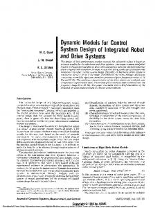
Host f C
3 Web Cam
Cbnt 3
h o i Fidbodt
1 Remote Site
Local Site
Fig. 1: System Architecture Design the operator receives feedback of forces being applied by the end-effector, or when the manipulator is compliant. Teleoperation errors involve undesirable manipulations, such as mis-positioning of the end-effector with respect to other objects, a hit and miss trial approach by the operator to achieve appropriate contact between the manipulator and object, and slipping of an object which has been gripped by the manipulator. Some of these teleoperation errors may be attributed to human error, such as mistakes and slips. Mistakes occur due to incorrect interpretationof the remote environment or the task, or when an incorrect manipulation sequence is selected even with correct interpretation of the environment. Slips are accidental movements of the manipulator caused by the operator, while other errors could be attributable to the fact that the user does not get sufficient feedback from the remote site.
controls the hardware should be created as a plug-in component package. Plug-in contains binary codes that implement a defined set of functions.
C. Continuous Control Issues The user should have continuous control over the robot and receive continuous feedback about the remote environment. The update rate of the transmitted video images should be as fluent as possible to provide a good feeling for reality. In the other hand, the control system should be designed to handle the problem when having many users accessing at the same time. It is important to allow only one user on continuous control at a particular time.
III.
SYSTEM OVERVIEW
B. Response Time Issues
While an operator is waiting for a response from the telerobot they are unable to pldsubmit the next request. To minimise this waiting period the response time should be as small as possible. Response time tr is defined as [3]:
Where tp is request processing time, tC is time taken to initialise communication (approximately 1 second), Ds and Dr are total data submitted and retumed, and vl is the transmission speed of the link. As a server of web content there is no control over the speed of the lmk, therefore minimum response time can only be achieved by fast processing of a request and minimum transmission of data. For a typical robot request 8 seconds is spent processing (a large portion of this being dead time while the robot moves) while data transmission can take over 15 seconds. Hence in this application data reduction is likely to be more beneficial than reducing response time. One way of doing this is by minimising image sizes presented to the operator. Further reduction in data size can be achieved by minimising data transmissions to robot controller in remote site. The part of the software that
The telerobot system basically consists of three main hardware systems that must be integrated. These systems are robot system, camera system and host computer system. Robot system includes robot controller and its arm.The robot is a fixed base Rhino XR-4 robot that has five degree of freedom (5 DOF) and a gripper. The camera system is a web cam (Logitech Quickcam Pro) type that is used to capture the entire robot environment. These systems must be integrated together before being launched to Intemet by programming in host computer (Pentium 111). System architecture of this telerobot system is shown in Fig. 1 and its explanation is given below. A. Control Server The Control Server is a place that handles instructions and feedbacks to/from robot controller. The instructions command should be sent to controller via serial communication port if we want to move the arm and know the position of robot.
B. Image Server Visual feedback server means a place that controls the camera images feedback before launching Intemet server.
11-339
So, the program that must be written to capture the real image of robot depends on camera driver type.
C. Web Server The web server system consists of three basic services. These three services are login service, system manager service and Common Gateway Interface (CGI) script service. The login service provides communication with the telerobot system by requesting a password and allows the system manager to get information about established connection. This part is important to allow system manager to arrange the priority user to control the telerobot system by following the database. The CGI script is used to integrate with control and visual feedback server before launching to client site through graphic user interface (GUI). The connection of this system into Intemet is using Transmission Control Protocol and Intemet Protocol (TCP/IP). TCP/IP is a software-based communications protocol and it handles errors in transmission, manages the routing, the delivery of data, and control the actual transmission by the use of predetermined status signals [4].
A. Control Scheme Control system for this telerobot is classified and shown in Fig. 2 as closed-loop system. The closed loop systems are more accurate since they can detect any error in the output and adjust for it. The user at Client PC is able to submit individual or a sequence of moves to the robot by submitting the instructions command to Server PC. The Server PC will send or modify commands if they exceed the robot’s workspace to robot controller. Users can view the latest position and live image as a robot feedback action. If no action is shown in live image action, the user must send again the command. The live image from camera is also as a feedback to determine that the robot moves or not.
m Fran
w
-----------
1
Fig. 2: Closed-loop Control System B. Robot and Controller Description This telerobot is using XR-4 series Robot Arm produced by Rhino Robots Incorporation, Unitpd State of America. The XR-4 arm is a five axis revolute coordinate robot arm
with a motor driven gripper [5]. The arm can be extended to 22.5 inches and has lifting capacity of 2.2 pounds. All axes of robot are controlled by dc servo motors using incremental optical encoders for feedback. Gripper are also controlled with a DC servo motor/encoder combination. Major axes include a limit switch that is used to position the robot to a home position. This robot can be driven by Mark IV controller. The Mark IV can be programmed via a host computer using any programming language or through the attached pendant. Maximum flexibility is provided when under host mode using RS232C serial communication. In addition, the Mark IV can read eight inputs, eight switch inputs and control eight outputs. In this controller, there are more than 80 kernel commands divided into the following categories: 0 System functions 0 Motor functions 0 Gain functions Teach Pendant functions 0 Configuration functions 0 Inputloutput functions
The robot needs programs - for its controller to execute. Similarly to telerobot system, it needs programs to control and produce the control panel interface to the web (intemet). There are three parts to be programmed namely robot control program, camera image program and graphics user interface (GUI) which would be developed by following the design approach. Robot Control Programming Robot control programming depends on the controller capabilities and styles. At present, there are three styles of robot controllers: the limit-sequence controller, the pointto-point controller and the continuous-path controller. Each has unique programming requirements [6]. The limited-sequence controller is used on the limitedsequence (or bang-bang) robot. The simplest bang-bang robots are pneumatic-powered and have a mechanical controller. Their application programming is done by mechanical set-up, such as using a motor to turn a timing drum. More modern this robot operating systems use electronics circuit and read only memory (ROM). Whether electronic or mechanical, the operating system translates applications program commands into pneumatic value activations. Whereas, the point-to-point controller uses some type of electronics memory to record of number of positions for the manipulator. Each position represents a value for each axis and each feedback sensor for the robot. It must also support control panels and teaching pendants. The last type of controller is continuous-path. This controller must be able to record and play back the robot’s position many times each second. This requires an electronic memory many times larger than that possessed by a point-
11-340
to-point controller. Most continuous path controllers use sensor information to keep track of position. This telerobot system is using the point-to-point controller type. So, the program should be design following the controller specifications. In this system, C++ programming language was used to program the robot control system. In order for Host PC to talk with the Mark IV controller, the communication link and protocol must be established. This must be done each time a program run. An open serial communication program is shown below [7][8]. DCB dcbCommPort; hComm = CreateFile("C0MI't GENERIC-READ I GENERIC- WRITE, 0, //exclusive access NULL, //no security OPEN-EXISSTRVG. 0, //no overlapped 110 NULL); //null template
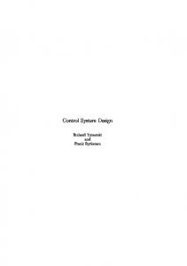
controller in the user interface has to be designed such that the user can effectively control the robot. a s GUI was developed using Hyper Text Mark-up Language (HTML) and C++ Builder. The C++ builder 4 Web Broker Technology allows developer to built CGI Web server applications without having to worry about too many low-level details. The Robot Control Programming was launched to web page (internet) after program in CGI Web Broker. HTML was used to integrate CGI - Robot Control and Camera Live Image page to one web page by using FRAME and FRAME technology. The GUI for this basic telerobot is shown in Fig. 4 and is worlung successfully.
V.
FUTUREWORK
SetupCOmmfiComm. 128. 128); GetCommTimeoutsfiComm,&ctmoOld); ctmoNew.ReadTota1TimeoutConstant = 100; ctmoNew.ReadTotalTimeoutMu1tiplier= 0; ctmoNew.WriteTotalTimeoutMultiplier = 0; ctmoNew.WriteTotalTimeoutCotant = 0; SetCommTimeoutsfiComm, CectmoNey); dcbCommPort.DCB1ength = sizeof(DCB); GetCommStatefiComm.&dcbCommPort); BuildCommDCB("96OO,N,8.1 ", CedcbCommPort); SetCommStatefiComm, &dcbCommPort);
To send datakommands to the serial port the WriteFile call is used. For example, the following call sends " G O (open gripper) command to the Mark IV: WriteFile(hComm, "GOlr", 3, &IpNumber, NULL);
If a command sent to the Mark IV is a responsive command, that is, one that results in data being sent back to the host, the data is retrieved using the ReadFile call. Camera Image Programming Live image from camera (web cam) is a robot movement feedback. We can know that robot have moved or not. Therefore the programming of camera is very important to capture live image. Normally, the web cam camera can capture the image up to 30 frame per second (as)based on image size, resolution and computer system. This image feedback was developed using Java programming language. Java is an ideal development tool for web cam applications because it has an applet for easy changing of the image [9]. Graphics User Interface (GUI) One of the most important components of any telerobotics system is the user interface, as it determines the extent to which the user can sense the remote environment and consequently control the manipulator. The display in the user interface should be designed so that the user receives sufficient information about the remote environment. The
There are several parts in which the intemet-based telerobot will be improved and developed: The old syitem will be change to the new system architecture (Fig. 3) by adding the padtilt/ zoom camera used to view entire robot environment and a web cam will be attached on gripper. So that, the control system for camera movement will be developed. The robot control package will be improved for better performance of time delay response. The program as continuous-path controller will be built to record and play back the robot's position movement. New GUI elements should be created to improve the control over the robot arm by considering the robot and camera control panel, zoom panel and record of movement panel.
VI.
CONCLUSION
This paper has described a basic design approach for telerobotics control system, general system architecture and development of basic telerobotics system especially its control system. The major task in this project is the programming part in accordance with the hardware's specifications and the performance of programming language. Robot control system has been developed by using C++ programming language, whereas Java programming language has been used to programthe
11-34 1
Send mail i o
[email protected]!se.utm.W with questions or comments about thk web rife.
I
rl
Fig. 4: Graphics User Interface camera image feedback. Both of these systems are combined together and produced in World Wide Web (WWW) by using HTML technology. The future work development also has been described to improve the telerobot system.
[4] S. Kuppuswami, Marie Stanislas Ashok, Paul Rodrigues and K. Palanivel. “Design Patterns On TCP/IP”. Proceeeding of International Conference on Robotics, Vision and Parallel Processing for Automation (ROVPIA’99), p. 436-445, 1999. * [ 5 ] Mark IV 8 Axis Controller Owner’s Manual Book
VII.
Version 4.01, United State of America: Rhino Robots Inc. August, 1990.
ACKNOWLEDGEMENTS
The authors would like to thank the Malaysian Ministry of Science, Technology and Environment for sponsoring this work under IRPA 09-02-06-0022. VIII.
REFERENCES
[l] K.P. Leu, M.H. Ang and Y.S. Wong. “A Telemanufacturing Workcell Over the Internet”. Proc. SPIE Vol. 35247, Telemanipulator and Telepresence Technologies V, p. 230-23, 1998. [2] Anu Rastogi, Design of an Interface for Teleoperation in Unstructured Environments using Augmented Reality
Displays, Canada : University of Toronto. 1996. [3] K. Taylor and B. Dalton. “Issues in Intemet telerobotics”. In International Conference on Field and Service Robotics (FSR 97), p. 151-157, Canberra, Australia, 8-10 December 1997.
11-342
[6] J. L. Fuller, Robotics: Introduction, Programming and Projects, New York Macmillan Publishing Company. 1991. [7] J. Miano, T. Cabanski and H. Howe, Borland C++ Builder How-To,United State of America: Waite Group Press. 1997. [8] K. Reisdorph et al, Borland C++Builder 4 Unleashed, United State of America: S a m Publishing. 1999. [9] J.Dwight and M.Erwin, SpecialEdition Using CGI, United State of America: Que Corporation. 1996