The design of high performance motion controls for industrial robots is based on accurate ... of the integrated robot and drive system models on controller design. ..... 131-135. 15 Book, W. J., and Majette, M., "Controller Design for Flexible,.
M. C. Good L. M. Sweet K. L. Strobel General Electric Company, Corporate Research and Development, Schenectady, N.Y. 12345
Dynamic Models for Control System Design of Integrated Robot and Drive Systems The design of high performance motion controls for industrial robots is based on accurate models for the robot arm and drive systems. This paper presents analytical models and experimental data to show that interactions between electromechanical drives coupled with compliant linkages to arm link drive points are of fundamental importance to robot control system design. Flexibility in harmonic drives produces resonances in the 5 Hz to 8 Hz range. Flexibility in the robot linkages and joints connecting essentially rigid arm members produces higher frequency modes at 14 Hz and 40 Hz. The nonlinear characteristics of the drive system are modeled, and compared to experimental data. The models presented have been validated over the frequency range 0 to 50 Hz. The paper concludes with a brief discussion of the influence of model characteristics on motion control design.
Introduction The successful design of any high-performance control system is based on accurate knowledge of the dynamics of the physical plant. This knowledge is particularly important when the "unmodeled dynamics", physical effects not included in the model, produce poles near the imaginary axis. If the control design does not account for these lightly-damped poles, there is great risk that the closed-loop system will become unstable or exhibit very poor robustness to variations in plant parameters. The design of multivariable controllers for industrial robots is a subject of great current interest. Nearly all papers in the literature on the subject of robot motion control are based on models for the arm that, based on the results of research presented in this paper, are inadequate for a large class of contemporary arm mechanical designs. Since there are major differences in the dynamic behavior of real robot arms from the idealized models found in the literature, it is difficult to assess the benefits to be obtained through implementation of advanced control schemes. The principal limitation of published models for industrial robots is the assumption that their dynamic behavior is represented adequately by interconnected rigid bodies driven by actuators modeled as pure torque sources or as first-order lags. It is noteworthy that there is very limited published experimental evidence to substantiate this assumption. In contrast, in this paper the importance of dynamic interactions between the multiple link arm and its electromechanical drive systems is demonstrated through analysis and experimentation. Specifically, this paper addresses the following aspects of model development for the purposes of control system design for real industrial robots: Contributed by the Dynamic Systems and Control Division for publication in the JOURNAL OF DYNAMIC SYSTEMS, MEASUREMENT, AND CONTROL. Manuscript
received at ASME Headquarters, January 29, 1985.
(A) Identification of resonant behavior induced through dynamic interactions of drive motors and the robot arm, coupled by harmonic drives and linkages with series compliance. (B) Characterization of structural modes of the robot arm, including an assessment of the relative importance of flexibility in the drive system versus the arm links themselves. (C) Characterization of nonlinearities in the drive system, due to motor current limiters, Coulomb friction, and stiffening spring characteristics in the harmonic drive. The paper concludes with a brief discussion of the influence of the integrated robot and drive system models on controller design.
Limitations of Rigid Body Robot Models Nearly all models for robot dynamics presented in the literature are based on the assumption that the arm is a linkage of connected rigid bodies, as exemplified by the widely-cited references in [1-5]. Using the Newton-Euler, Lagrange, Kane, or other approaches, the kinematics and dynamics of multiple link robot arms are derived and reduced to the following form: H(.q)q + C{q,q) + G{q) + K{qYM=T (1) In this equation q is a vector of robot joint angles, H is a moment of inertia matrix, C is a matrix specifying centrifugal and Coriolis effects, G is a vector specifying gravitational effects, K\s a Jacobian matrix relating joint torques to M, the vector of forces and moments applied to the end effector, and Tis the vector of torques applied by the actuators at the drive points on each arm link. The characteristics of equation (1) as applied to multiple
Journal of Dynamic Systems, Measurement, and Control
MARCH 1985, Vol. 107/53
Copyright © 1985 by ASME Downloaded From: http://dynamicsystems.asmedigitalcollection.asme.org/ on 04/25/2016 Terms of Use: http://www.asme.org/about-asme/terms-of-use
FORE ARM
ROTATION FREQUENCY. Hi
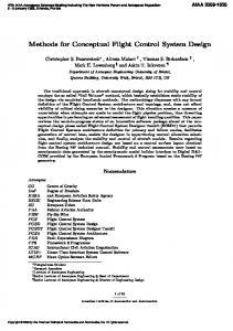
Fig. 2 Comparison of linearized model and measured transfer functions for resonant robot joint servodrive system Fig. 1 Geometry of industrial robot used for analysis and experimental studies
/
link robot arms have been exhaustively discussed in the literature, with particular attention paid to:
A
(A) Dependence of effective inertia, reflected at the actuator drive point, on robot arm configuration and end-effector pay load. (B) Cross-coupling of the set of second-order differential equations due to Coriolis, centripetal and inertia forces. (C) Nonlinear behavior due to arm geometry and crosscoupling effects. In much of the literature, the actuators providing the drive torques are modelled as pure torque sources, or as first-order lags. This assumption is the Achilles' heel of the class of robot dynamic models represented by equation (1). References [6, 7] are among the few studies to recognize the significance of drive system and mechanical compliance. As a vehicle for demonstrating the importance of drive system compliance (as opposed to arm link flexibility), in the present paper we select the robot shown in Fig. 1 as representative of a large class of contemporary industrial arms. The robot is powered by electro-mechanical drives, consisting of d-c or a-c motors in series with a harmonic drive used for speed reduction. (A "harmonic drive" is a compact, high-torque, high-ratio, in-line gear mechanism incorporating a rigid "circular spline", an elliptical "wave generator", and a nonrigid "flexspline".) The motors and harmonic drives are mounted on or near the base, with drive torques transmitted to the drive points on the arm links via mechanical links such as bars or chains. Mounting of drive motors in this manner, in contrast with mounting at the joints, can been shown (using the methods of [14]) to provide superior dynamic characteristics. The dynamic response of the integrated system consisting of the drive motor, harmonic drive, linkages, and arm may be measured experimentally by recording the motor current, motor velocity (tachometer feedback signal), and arm motion (integrated accelerometer signal) as the servo is excited with random or sinusoidal input signals. For a given (small) signal level, the drive system may be characterized by a linearized frequency response function. An example of such a frequency response function, computed through FFT analysis of signals recorded during random excitation testing, is shown in Fig. 2. The strong anti-resonance/resonance phenomenon exhibited in Fig. 2 is typical of electro-mechanical drives with compliance in series with the load, and is grossly divergent from the torque source or first-order lag representation of the drive system cited earlier. Although this behavior is well-known by the industrial controls technical community, it has been ignored in much robotics research. 54/Vol. 107, MARCH 1985
//I
Phase F,
Mag
Frequency (Hz)
Fig. 3 Results of frequency response testing using impact hammer, showing drive system resonance (9 Hz) and away and yaw structural modes (14 Hz and 40 Hz)
The existence of resonant behavior inside the robot motion control loop has a dramatic impact oh control system design, providing the motivation for development of the models presented in the following sections. For example, one approach to improving robot motion control performance is to decouple the dynamics of the robot links through nonlinear control [8, 9]. The decoupling action performed by the controller is particularly significant in the same frequency range as the above resonant behavior. Decoupling controllers that do not take this strong resonance into account have little chance of successful implementation. Similarly, adaptive control is an alternative approach proposed frequently [10-12]; however, from adaptive control theory it is known that "unmodeled dynamics" such as this drive system resonance lead to severe stability and robustness problems [13]. The existence of drive system interactions does not preclude future use of nonlinear or decoupling control strategies; rather it demands that realistic robot and drive system models be used in development of implementable algorithms. Transactions of the ASME
Downloaded From: http://dynamicsystems.asmedigitalcollection.asme.org/ on 04/25/2016 Terms of Use: http://www.asme.org/about-asme/terms-of-use
25. 15. .
10.
MODEL
TEST
-
6.3
kz, Cj - TORSIONAL k«,c x -LATERAL
3.9 1 5
2.5 16
1 16
5C
20 0.0
k,c - TORSIONAL
^
TEST
-20. -40.
-
MODEL
-60. -80.
Fig. 4 Four degree of freedom dynamic model for robot drive system flexibility. Model shown here is for base rotation drive, but also applies to fore-arm and upper-arm drives.
1 5
-100 1.6
1 16
FREQUENCY. H i
Linearized Models for Electromechanical Drives In this section models are presented for the robot electromechanical drives valid for small motions about a given arm position with fixed payload. These models are useful for design of linear controllers, a point of departure for the more general nonlinear case. The range of variation of model parameters with varying payload and arm position is indicated at the end of this section, information which may be used in studies of control system robustness and adaptive control strategies. Extensions of the linear models to include nonlinear effects are presented in a later section. Resonant Joint Control Models. For the robot shown in Fig. 1, the drives for base rotation, forearm, and upper arm have resonant responses to motor torque inputs similar to those shown in Fig. 2. The discussion in this section pertains to the base rotations specifically, with the concepts directly extendable to the other two drives. As well as its response to servo motor inputs, exemplified by Fig. 2, the response of the arm to external torques and forces (e.g., inertial loadings, tool forces) is of interest. Figure 3 shows a frequency response function for the lateral acceleration of the wrist in response to a lateral force applied at the wrist, measured by an impulse hammer technique. Three resonances below 50 Hz can be observed in this response. Note that the characteristics of the velocity servo will have some influence on these results. The dynamic characteristics which are displayed in Figs. 2 and 3 for frequencies up to 50 Hz may be accounted for by a four degree-of-freedom (DOF) model of the drive system coupled to the robot arm, as illustrated in Fig. 4. The four degrees of freedom are rotations of motor and base inertias, plus yaw and sway rigid body modes of the robot forearm. Note that the four degrees of freedom for the dynamic model of this figure should not be confused with the conventional kinematic "degrees of freedom" associated with the five controlled axes of the robot. The main source of flexibility and energy dissipation is the harmonic drive. Additional flexibility in the upper-arm links allows lateral and rotational motions of the forearm. The dynamic modes of this system consist of an aperiodic "rigid-body" mode, a "torsional" mode in which the motor inertia oscillates against the combined inertia of the base and arm, a "sway" mode in which the predominant motion is a lateral oscillation of the forearm, and a "yaw" mode in which the forearm oscillates about a vertical axis. The torsional mode is responsible for the resonance at 9.6 Hz in Fig. 2; the torsional sway and yaw modes give rise to the resonances at 9, 14, and 40 Hz in Fig. 3. Journal of Dynamic Systems, Measurement, and Control
Fig. 5 Comparison of linearized model and measured transfer functions for non-resonant robot joint servodrive system
The sway and yaw modes are not significantly excited by motor inputs, so that for the frequency bandwidth of interest for position control (10 Hz, say), perhaps only the rigid-body and torsional modes are of concern, and a simplified twoinertia model could be used for control design purposes. However, it should be noted that both of the higher frequency "structural" modes could be excited by forces arising from tool/workpiece contact or from inertia forces generated by wrist motions. In some configurations the sway mode could be excited by Coriolis forces arising from upper-arm and forearm motions. The mechanics of the "structural" modes are considered further in Section 4. Assuming linear elements for the model of Fig. 4, and combining the base and arm inertias into one inertia /, (referred to the motor shaft speed), a transfer function model may be derived that accounts for the magnitude and phase characteristics presented in Fig. 2. For a high current servo loop gain and small armature inductance, the transfer function between motor torque and current command is essentially a pure gain Kt. Then, the motor velocity Wm and the load velocity Wi in response to current commands Ic and load torque disturbances 7", are given by: Wm Ki[Jls2 + (Bi+c)s+k]
cs+k Jms2 + {Bm+c)s + k
Kj(cs + k) D"
(2)
where D" = JmJxs} + [J,„ (5, + c) + J, (B,„ + c)]s2 + [k(J„, + Jl) + B,„Bl +c(B,„ +£,)]s + £0Bm +5,). Using component data or experimentally identified parameters for the motor and drive system, the desired drive system model to be used in control system design may be developed for various motion amplitude levels. Using the shorthand notation: K(a)[z,w] to represent: K{s/a + l)[(s/w)2 + 2z(s/w) + 1], MARCH 1985, Vol. 107/55
Downloaded From: http://dynamicsystems.asmedigitalcollection.asme.org/ on 04/25/2016 Terms of Use: http://www.asme.org/about-asme/terms-of-use
1 TEST
10 £&
3.1
1
,0