can lead the path of magnetic piston based alternative power sources. ... linear generator) as it can produce electric power and mechanical power at same time.
International Journal of Advances in Engineering & Technology, May 2012. ©IJAET ISSN: 2231-1963
DESIGN AND DEVELOPMENT OF LINEAR MAGNETIC GENERATOR Manoj Gattani Research Engineer, Innovative Green Energy Technologies, Dehradun, India
ABSTRACT Design and development of Linear magnetic Generator capable of producing mechanical and electrical output at same time hereafter referred to as Gopi Gen is presented in the paper. The Gopi Gen includes three important parts, part a, part b and part c. Part a and part c are same and includes coil, magnetic piston, crank which is attached to magnetic piston and flywheel for constant speed of the magnetic piston movement. Part b contains acceleration zone, single sides and/or double sided magnetic piston, drive assembly of the acceleration zone. The objective of the paper is to provide a high efficient magnetic piston based fuel less generator for power generation. A working model of high efficient, zero emission is developed for power production which can lead the path of magnetic piston based alternative power sources.
KEYWORDS:
Permanent Magnet, magnetic piston, Repulsive Magnetic Force, Acceleration zone, electrical & mechanical power.
I.
INTRODUCTION
The working of the Gopi Gen is based on the principle of faraday’s electromagnetic induction principle and reciprocating movement of piston. The Gopi Gen is a blend of Gopi engine (Gate operated repulsive magnetic piston engine) and Gopi generator (Gate operated permanent induction linear generator) as it can produce electric power and mechanical power at same time. Gopi Gen works as generator in the sense as it can produce electric power. For this, the permanent magnet in form of magnetic piston passes through the fixed coils. According to Faraday’s law when a magnet moves with respect to a electrical coil, a current will induce in it. The direction of the induced current is such that it will oppose the cause of its production. The induced current or simply current depends upon many factors like rate of change of magnetic flux, strength of magnetic field with respect to space and time, number of turns in the coil, electric resistance of the coil, area of the coil (diameter of the coil) and the velocity of the moving magnet with which it enters or leaves the coil. The Gopi Gen works as engine as it can produce mechanical power. The magnets in form of magnetic pistons move to and fro in the cylinder. The cranks attached to the magnetic piston will produce reciprocating motion and mechanical power can be gained at the common shaft of the cranks. The mechanical power depends mainly on the repulsive force between the magnetic pistons.
II.
DESIGN AND DEVELOPMENT
As the Gopi Gen is a blend and advancement of Gopi Engine[2] and Gopi Generator[3], the operational problems of the Gopi engine and generator were illuminated in the Gopi Gen. In Gopi engine, when the movable magnet in form of magnetic piston brings near to Gate of the magnetic shielded material near the TDC position, it virtually attached to the Gate and in this condition, it requires more input power to operate the Gate. The opening and closing mechanism of the Gate not only reduces engine efficiency but also increase its manufacturing and running cost.
820
Vol. 3, Issue 2, pp. 820-825
International Journal of Advances in Engineering & Technology, May 2012. ©IJAET ISSN: 2231-1963 In Gopi generator, the movable magnet has to change its direction of movement by 1800 after getting power stroke from the fixed magnets. This change in direction brings the movable magnet to zero velocity for a moment. It decrease the generator efficiency and increase running cost of it as Acceleration zone has to work more to attain the same speed with which the movable magnet should passes through the electrical coil. In Gopi Gen, the magnetic shielded Gate with its opening and closing mechanism is removed permanently. By doing this, not only the manufacturing and running cost of the Gen is reduced but its design became simpler. The efficiency of the Gen is increased by a large extend as no more input power is required to operate the Gate but also the speed of the movable magnets in form of magnetic pistons does not decreased at any step of the operation. For the design of Gopi Gen, two single sided magnetic pistons are clamped with crank and flywheel assembly at both end of the embodiment. These opposite parts with electrical coils form the part a and part c of the Gen. The part a and part c along with part b are placed on the Gen track. Opposite poles of the magnetic pistons of part a and part c are facing each other. Let these magnetic pistons of part a and part c are Pa and Pc, then if North Pole of Pa is facing inside the track then South Pole of Pc will be facing inside the track. Magnetic piston of part b that is Pb is placed on the track in such a way that it will be facing same pole to that of Pa and Pc. This means the pole of Pb towards Pa will be North Pole and pole of Pb towards Pc will be South Pole. In another design, only part a(or part c) and part b is used. The part a and part b are placed end to end on the gen track. The acceleration zone of part b will be used to move the Pb and the movement of the Pb will produce motion in the Pa. For smooth motion of Pa and Pc, the individual cranks are coupled to a common shaft. In Gopi Gen, three permanent magnets in form of magnetic pistons and two coils are required with crank and flywheel assembly. To control the movement of the Pb and to synchronize the Pa, Pb and Pc motions, micro processor based control units are designed for the Gopi Gen. Two single sided magnetic pistons are placed end to end of the embodiment of the Gopi Gen. Third double sided magnetic piston is placed in between of these magnetic pistons. The double sided magnetic piston is used to move to and fro through its center line with help of the acceleration zone. The end to end magnetic pistons are used to pass through the coil all the times. Here design of some of important component is described.
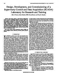
2.1. Magnetic piston Magnetic piston is constructed with permanent magnet and non metallic, non magnetic hollow cylinder. In single sided magnetic piston, the permanent magnet is clamped at one side in fixed position inside the cylinder. This combined form of the cylinder and the magnet is to be known as magnetic piston. The other side of the single sided magnetic piston is attached with crank through connecting rod. The magnet forms the top side (or piston head) of the piston.
Figure1: Single sided magnetic piston
In double sided magnetic piston, magnets are used throughout the cylinder so that permanent magnets should be projected outward from both side of the cylinder. If south pole is facing from one side then
821
Vol. 3, Issue 2, pp. 820-825
International Journal of Advances in Engineering & Technology, May 2012. ©IJAET ISSN: 2231-1963 from other side there be north pole facing out ward from the cylinder. To clamp it with acceleration zone, special non metallic, non magnetic hooks are used.
2.2. Gen track The magnetic pistons are used to move on Gen track. The track is made up of non metallic, non magnetic material. In traditional engine, the pistons are used to move in the piston cylinders, but in Gopi Gen the pistons are move on this track. The benefit of using Gen track is that there is less contact between the track and magnetic pistons and hence less frictional losses are associated as compared with traditional diesel/petrol engines.
2.3. Acceleration zone The piston of the part b i.e. Pb is to move to and fro motion on the Gen track in between the Pa and Pc. The cranks of Pa and Pc rotate because of the power stroke happen between Pa & Pb and Pc & Pb. To produce power stroke at a regular interval the Pb is to be moved on the track with help of Acceleration zone. The Acceleration zone is an assembly of mechanical and electrical devices which produce linear motion. The movement of the acceleration zone is controlled using advance micro processor based control units and powered by some external sources like battery.
III.
WORKING OF THE GOPI GEN
The Gopi Gen works on repulsive properties of magnets. When two magnets of same pole come near to each other they will face repulsive force between them and will try to move in direction of stronger force. In Gopi Gen the magnets in form of magnetic pistons faces repulsive force and make a continuous motion. The arrangement of pistons is made in such a way that Pa and Pc faces repulsive force from pb at constant interval. The repulsive force between Pa and Pb or Pc and Pb will be known as power stroke. The pa and Pc are arranged in such a way that they will bring again and again near to Pb to generate power stroke. The position of Pb with respect to Pa (or Pc) is managed in such a way that when the Pa (or Pc) approaches to Pb there will be no repulsive force between them. The movement of Pb is controlled with the help of acceleration zone and micro-controller units. Initially, when the Gen is at rest position, the Pa, Pb and Pc will positioned in such a way that there will be no repulsive force between any of the pistons. Let say this position as neutral position of the Gen. At this time the Pa and pc are equidistance from Pb. The Pa is 2700 equivalent to crank rotation and Pc is 900 equivalents to crank rotation. The Pb is at neutral position. The Pa is moving towards its Top Dead Center (TDC) position (minimum distance from neutral position) and the Pc is moving towards Bottom Dead Center (BDC) position (maximum distance from neutral position). As the Pa is moving TDC position, the Pb will start moving towards Pa with help of acceleration zone. When the Pa approaches to its TDC position, the Pb will move very near to the Pa and will produce power stroke (power stroke happens only when Pa or Pc is at TDC position). At this time the Pc will approaches to its BDC position. Because of the power stroke between the Pa and Pb, the Pa will start moving towards its BDC position (similarly the Pc will start moving towards its TDC position) while the Pb will remain in stationary position there for some moment. When the Pa(or Pc)moves by 1500 the Pb will bring back to the neutral position. During it motion, when the Pa approaches to its BDC position and the Pc to its TDC position, the Pb will start moving towards Pc. When the Pc is at its TDC position the Pb will move to minimum approaches distance between the Pc and another power stroke will be produced between the Pc and Pb. Because of the power stroke, the Pc will start moving towards its BDC position (the Pa will start moving towards its TDC position) and the Pb will remain in stationary position for some moment. In this way the power stroke between Pa and Pc will be produced at an equal interval and motion of the pa and Pc will be continued. The working of the Gen is described here with illustrations [2],[3],[4]. These illustrations are taken from author’s work which were submitted to Indian Patent Office as Patent applications (patent pending)
3.1. Position 1 Initially the Pa and Pc are equidistance from Pb and because of the continuous motion the Pa is approaching to TDC position and Pc is approaching to BDC position. At this time Pb is at neutral
822
Vol. 3, Issue 2, pp. 820-825
International Journal of Advances in Engineering & Technology, May 2012. ©IJAET ISSN: 2231-1963 position. It means there is no repulsive force between any pistons. Pa and Pb are facing same pole and Pc and Pb are facing same pole.
Figure 2: The Pa is moving towards TDC position
The corresponding crank of pa will be at 00 (when Pa is TDC position) and the crank of Pc is at 1800(when Pc is at BDC position. Electrical coil is placed in between Pa and Pc to produce electrical power 3.2. Position 2
Figure 3: The Pb is moving towards Pa
As Pa approaches TDC position, the Pb will start moving toward Pa (with help of accelerating zone) and a repulsive force will be there between Pa and Pb. This repulsive between pa and Pb will be known as power stroke and will happen only when the Pa is at its TDC position and Pb is at its minimum approaches distances towards Pa. Because of this power stroke, the Pa will move towards its BDC position. Here the arrow shows the power stoke direction and position. (coils not shown)
3.3. Position 3
Figure 4: The Pb is is at neutral position as Pa moving towards BDC and Pc moving TDC
This time, Pa is an approach its BDC position (far away from Neutral position) and Pc is approaches its TDC position. As Pc approaches TDC position, the Pb will start moving toward Pc (with help of accelerating zone) and a power stroke will be there between Pc and Pb. With help of this power stroke, Pc will start moving toward its BDC position and Pa will start moving towards its TDC position.
3.4. Position 4
Figure5: The Pc is moving towards TDC position
823
Vol. 3, Issue 2, pp. 820-825
International Journal of Advances in Engineering & Technology, May 2012. ©IJAET ISSN: 2231-1963 After the power stroke, the Pc will start moving towards its BDC position and Pa will start moving towards its TDC position and the Pb will remain in stationary position there for some moment. After this, power cycle and rotation of the pistons and cranks will be maintained and continuous output can be maintained at the shaft of the cranks (mechanical power) and at the end of the coils (electrical output).
Figure 6: Working model of Gopi Gen
IV.
OBSERVATIONS
It is observed that the Gopi Gen can be used as standalone for power generation system as well as can be used as hybrid engine for vehicles. Some of important observations like thrust, efficiency and manufacturing and running cost are described here
4.1. Thrust of the Gen When the magnetic piston of part b i.e. Pb approaches towards piston of part a (or part c), it will bounce back because of heavy mass (inertia) of piston crank assembly of the part a or part c (combination of piston, crank, connecting rod, flywheel etc). This happen because in the operation of the Gopi Gen, the magnetic force cause the motion in the Pa and Pc. But at the same time the mutual contact between the magnets of Pa and Pb will act like momentum transfer from the Pb to Pa. If we consider the mutual contact between Pa and Pb as elastic collision between the Pa and Pb, the momentum transfer from Pb to Pa will take place only when the mass (inertia) of Pb is very large with respect to that of Pa or the speed of the Pb is more than that of Pa. In this case the Pb will not be re bounced back and the total magnetic force (hence momentum) can be transferred to the Pa and the Pa can move with maximum speed and hence maximum torque can be produced at the end of the common shaft. But increasing mass alone or speed alone of the Pb is not justified as if only mass increase the total weight and therefore initial cost of the Gen will increase and if speed alone increases the running cost of the Gen will increase as strong/powerful accelerating zone is required to maintain high speed of the piston b. So the mass (Mb) and velocity (Vb) of the Pb are to be increased in such a way that the product of Mb and Vb should give an economical balance in between the manufacturing and running cost of the Gen. It is also observed that when Pb is to retain at extreme position (after power stroke), the repulsive force between Pa(or Pc) and Pb will lasts for longer time and efficiency of the Gen increases accordingly. This can be done with help of acceleration zone, but operating acceleration zone also need input power. So stopping of Pb at extreme position is done with specially designed cam shaft which is synchronized with main crank shaft of the Gen. it is also found that this mechanism is also helps to overcome the counter momentum problem.
4.2. Efficiency of the Gen Efficiency of the Gopi Gen can be claimed theoretically more than unity as input is required to move the piston of the part b only. The Piston of the part a and part c are used to move because of the repulsive force between them (power stroke). The intensity of power stroke directly depends upon the
824
Vol. 3, Issue 2, pp. 820-825
International Journal of Advances in Engineering & Technology, May 2012. ©IJAET ISSN: 2231-1963 magnetic pole strength of the magnets of the magnetic pistons. So power stroke of any strength can be produced using magnets of desire capacity but the input power to move the Pb is not affected.
4.3.
Low cost of the Gen
The running cost as well as manufacturing cost of the Gopi Gen is very less as compared to the existing diesel/petrol engine of the same rated capacity. In traditional diesel (or petrol) engine we require a complex mechanism to burn fuel in closed chamber but in the Gopi Gen such kind of mechanism is not required. The design is very simple compared to the diesel/petrol engines.
V.
CONCLUSION
Magnetic engine as a prime power generation source can have many benefits like it does not depend on any type of fuel to run it, no waste production at any stage of the power generation process and no extra cost is required for power storage system. Gopi Gen with its high efficiency has also many benefits over existing techniques like its running cost is very less compared to fuel based engines, almost maintenance free, one time investment for the end users, portable in size, independent of climatic conditions and eco friend device. The Gopi Gen can be used as stand alone for power generation or can be used as hybrid engine to run vehicles.
REFERENCES [1]. [2]. [3].
[4].
[5]. [6]. [7]. [8]. [9]. [10]. [11]. [12]. [13]. [14]. [15].
Butler,Kala“Electromagnetic reciprocating engine” US Patent, US 7,557,473. Gattani M.K. “Gate operated repulsive magnetic permanent induction linear generator” International Journal of Earth Sciences and Engineering, Volume 05 No 01 SPL, Page 702-706, January 2012. Gattani M. K “ Fuel free engine for power generation” Proceedings of Annual International Conference on Sustainable Energy And Environmental Sciences-2012, Global science and Technology Forum, Singapore, Page 1-5, 13-14th February,2012. Gattani M.K. “ Magnetic engine: Alternate energy source beyond oil” Proceedings of National Conference on Emerging Trends in Energy Engineering-2012, Dehradun Institute of Technology, Dehradun, Page 97-101, 23-24th March,2012. Harry Paul “Apparatus and process for generating energy” ,US Patent, US 6,954,019. Konotchick, “Linear motion electric power generator” US Patent, US 5,818,132 Mah, “Faraday flash light” US Patent, US 6,729,744B2 Mc Carthy, “Energy producing apparatus utilizing magnetic pistons”, US Patent, US 7,330,094 Minato “Magnetic rotating apparatus” ,US Patent, US 5,594,289. Patton “Ceramic magnet motor” ,US Patent, US 5,057,724. Studer, “Linear magnetic generator” US Patent US 4,315,197 Takara “Electromagnet piston engine” ,US Patent, US 6,049,146 Togare,Radhakrishna Shesha Iyengar “Magnetic piston engine”, US Patent, US 7,667,356 B2. Wolfs,Marc.J.M, “Piston engine” US Patent, US 4,998,460 Wortham,Charles, “Vehicle with magnetic engine”, US Patent, US 5,219,034
Biography Manoj Gattani had completed his engineering and masters degree from Jodhpur University. Mr. Gattani is working for magnetic engines for power generation from last 2 years. beside this he has a keen interest in waste to energy and solar and biomass form of energy for power generation. Mr. Gattani has five Indian patents(pending) and won several awards like young scientist award 2011, best technology of the year, 2011 etc. Mr Gattani is performing Ph D in Green Energy & Power Generation System from University of Petroleum and Energy Studies, Dehradun, India
825
Vol. 3, Issue 2, pp. 820-825