was achieved by designing a monitoring circuit; this monitoring circuit measures the quantity of fuel inside a fuel tank at four different levels representing four ...
International Journal of Research and Reviews in Computer Science (IJRRCS) Vol. 2, No. 6, December 2011, ISSN: 2079-2557 © Science Academy Publisher, United Kingdom www.sciacademypublisher.com
1357
Design and Implementation of a Computer Controlled Fuel Level Monitoring System Afolabi Adeolu and Oke Alice Department of Computer Science and Engineering, Ladoke Akintola University of Technology, Ogbomoso, Nigeria
Abstract – This work discussed the design and implementation of a computer controlled fuel level monitoring system. This was achieved by designing a monitoring circuit; this monitoring circuit measures the quantity of fuel inside a fuel tank at four different levels representing four sensors. If the fuel goes below the minimum level, the alarm system embedded in the circuit will be triggered. Anything above this level, the alarm will go off. As the level of fuel increases, it displays on the computer screen when it reaches a particular sensor level. When the fuel level rises to the fourth and final level which represents the maximum, the alarm will be triggered for a while before going off automatically. The monitoring circuit communicates with the computer system with the aid of an interface. A visual basic program is used to interpret the signal being sent from the device and displays the output on the computer screen. Keywords – Implementation, Computer Controlled, Monitoring System
1.
Introduction
The term fuel is generally limited to those substances that burn readily in air or oxygen, emitting large quantities of heat. Fuels are used for heating, for the production of steam for heating and power purposes, for powering internalcombustion engines, and for a direct source of power in jet and rocket propulsion. Fuel is an important need of a vehicle, without it, the vehicle cannot move. It is an essential of motorist in their everyday activities. The only place where motorist can get the supply of fuel is at the fuel station which makes them being frequently visited by motorist. Due to this, fuel station will have to frequently measure the quantity of their storage tank so as to refill when the fuel in the storage tank is low. The fuel attendant uses a long rod to measure the level of fuel in their storage tank in developing countries. This is a slow and cumbersome process, due to this, there is need to design an automatic system to measure and display the quantity of fuel in the storage tank. This inform our decision to design an automatic fuel level monitoring system that will use a sensor in sensing the level of fuel inside the tanks and interpret it on the computer system in liters. The system will also have an alarm system to indicate when the fuel level in a particular tank is too low, and to trigger a beeping sound when the tank is full.
2.
Methodology
In this project, we designed a system that will sense the level of fuel in the tank and send it in form of a signal to a computer which is already interfaced with the monitoring system. The computer system will display the level of the fuel both digitally and analog via the aid of a pre coded program, the process is an automatic process.[7]
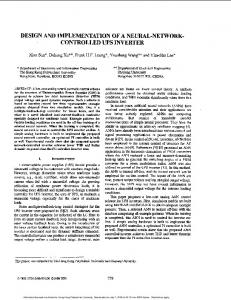
2.1. LM324 Circuit Description
Figure 1.0 Circuit diagram of LM324.
Figure 1.0 shows LM324 series is made using four internally compensated, two–stage operational amplifiers. The first stage of each consists of differential input devices Q20 and Q18 with input buffer transistors Q21 and Q17 and the differential to single ended converter Q3 and Q4. The first stage performs not only the first stage gain function but also performs the level shifting and transconductance reduction functions. By reducing the transconductance, a smaller compensation capacitor (only 5.0 pF) can be employed, thus saving chip area. The transconductance reduction is accomplished by splitting the collectors of Q20 and Q18. Another feature of this input stage is that the input common mode range can include the negative supply or ground, in single supply operation, without saturating either the input devices or the differential to single–ended converter. The second stage consists of a standard current source load amplifier stage.
A. Adeolu and O. Alice / IJRRCS, Vol. 2, No. 6, pp. 1357-1360, December 2011
3.1. Interfacing with Parallel Port The parallel port is used mostly for interfacing home made projects. This port will allow the input of up to 9 bits or the output of 12 bits at any one given time, thus requiring minimal circuit to implement many simple tasks. The port consists of four control lines, five status lines, and eight data lines. It is found mostly on the back of the PC as a D-type twenty five female pin connector. [3]. There are two ways of physically interfacing a device to a microcomputer. One way is to connect the device to the expansion slot on the system motherboard (by making use of plug in cards or boards) and the other is to use either of the serial port or the parallel ports.[1]. The signals from the parallel are TTL compatible, hence line driver are required for interfacing. During interfacing, not all the twenty five pins are needed. Eight pins are enough to do the interfacing. Table 1.0 the pins and their function. PINS
FUNCTION
2
D0
3
D1
4
D2
5
D3
6
D4
7
D5
8
D6
9
D7
The pins 18,19,20,21,22,23,24 and 25 are all ground pins. Those data pins are TTL level output pins. They put out ideally 0volts when they are in low logic state and +5volts when they are in high logic state. In real world, the voltages can be something different from ideal when the circuit is loaded. The output current capacity of the parallel port is limited to only few milliamperes. The idea of the interface can be expanded to control some external electronics by simply adding a buffer circuit to the parallel port. 3.2. Input The link between the computer and the outside world takes place through the interfaces. The simplest form of input is the digital input which is an ON or OFF closure that can be translated into binary 0 or 1. This is relatively easy to make compatible with computer circuitry. Examples of these are surface wetness and motor ON\OFF indication. 3.3. Output Interfacing can again be in different forms. Switch outputs are basically digital outputs, usually operating read relays that then provide a voltage free contact for control purposes. The analog form is used where a signal of valve related to the opening is required.
10K
7812
10k IN
OUT
7805
R1 150k
R6 10k
+5V +12V
IN
IN4007 AC
50V
50V
7 6
1
47µF
470µF
8
2 4
10k
1k
OUT
GND GND
4.7k C2 100F
555
7
2
R3 100R
3
C1815
The software part of this project work can be divided into the parallel port interfacing using printer cable and the programming codes to interpret the digital signal from the interface and display it on the computer system.
3.4. Overall System The overall fuel level monitoring system block diagram and the schematic diagram of the circuit are shown in the diagram below. The monitoring system will measure the quantity of fuel in the tank at a particular level and send it through the interface to the computer which will display the result.[4]
C1815
Software Development
1
6 3
100R
555
GND
+5V
1
2
3
a1
b1
a2
b2
a3
COM 4 1
S4 S3
a4 a1
CD4066
3.
1358
b3
b4 b1
5
6
7
8 5
33Ok 2
a2
b2
a3
b3
a4
b4
6
S2 S1
3
7
10k
10k
1k
330k 4
8
4 3 2 1 COM
Figure 3.1. Circuit Diagram of the monitoring Device.
4.
Implementation, Result and Testing
Implementing an analytical design of the circuit a shown previously involves the principle of the voltage divider rule was employed. Vs = [(R1 + R2)/R2] V1 + [(R3 + R4)/R4] V2 Where Vs = output voltage V1 = input voltage V2 = input voltage 2 R1, R2, R3 and R4 are resistances.
R1 Vin
= Vout
R2
Vout = [R2/(R1 + R2)] V
Figure 4.1. the voltage divider rule.
Taking the characteristics of the fluid that is petrol, although most fluids have a definite resistance, it was observed during experimentation that fuel has an almost insignificant resistance to electricity or electrical charges. Thus it suffixes to say that fuel is not a good conductor of electricity. In order to exploit this characteristic of fuel, the principle of voltage divider was used. In implementing this, a resistor (R2) is fixed and the second resistor (R1) is taken to be the resistance of the fluid or as a switch. Resistance (R1) is infinite when the two terminals are open or not touching the fluid at the same time. Since the resistance of air is infinite, the circuit is taken to be in open state and the output voltage is taken to be zero. When the two terminals or points are dipped into the fluid, the fluid with a known resistance will be closed and will give an output voltage.
BUZZER
A. Adeolu and O. Alice / IJRRCS, Vol. 2, No. 6, pp. 1357-1360, December 2011
Vout = (R2/ (R1 + R2)) Vcc AS OPEN CCT Assuming R2 = 100Ώ, R1 = ∞ Vcc = 5 volt Vout = [100/ (∞ + 100)] 5 = (100/ ∞) 5 = ∞ = 0 AS CLOSE CCT R1 = 200Ώ 100/ (200 + 100) 5 = (1/3)*5 = 1.6V. 4.1. Discussion In carrying out the implementation, a 240 volt supply voltage is supplied to the circuit. The step-down transformer will step down the 240 volts supplied to the circuit to 24v which was further rectified by using four diodes (IN4007) to dc voltage. Electrolytic capacitors with values 470µf 50v was first used to rectify the 24v to take or remove any unrectified ac. Since the expected Vcc to be used is 12v, a voltage regulator 7812 IC was connected to the capacitor to reduce the voltage from 24v to 12v. This 12v is to be supplied to the transistors (C1815) as Vcc.[6] These 12v dc is further rectified by using another electrolytic capacitor (470µf 50v) to remove any ac that might have escaped earlier rectification and then reduced to 5v using another voltage regulator 7805 IC. This further reduction became necessary because the 4066 IC used can only take and the computer system can also take 5v as input voltage. 4.2. Output The diagram, figure 4.2 shows what the user interface looks like when the program in appendix one is being executed. The first diagram assumes the fuel is at the minimum level.
9 have their output voltage at pin 1 and pin 5 and 10 product is output voltage at pin 4 with 7 as ground. Pin 14 acts as Vcc which is supplied with 12v. The common sensor is permanently immersed in the fluid. When the first sensor (S1) makes contact with the fluid or the conducting rod, a finite resistance is gotten which close the circuit with pin 2 whereby given an output voltage (Vout) of +5v at pin 8 which is then supplied to the computer so as to be displayed and also to the alarm system through series of transistors and diodes connected to form an AND logic gate and also through the relay and finally to the second 555timer in astable operation mode.[8] These operations are repeated when sensors 2, 3 and 4 all form close circuit through their respective output terminals such as pins 11, 1 and 9. Each time each of these sensors make a circuit close, the signal is set to both the alarm circuit and the computer system and these signal is display on the computer system through the aid of precoded software installed on the system. The approximate quantity of fuel in the tank is displayed as earlier stated and the exact quantity is displayed when the fuel level gets to the sensor height. These results were gotten since from research, the fuel stations have their specified levels the fuel in the tank have to reach before deciding it is time to refill or start selling. On going below the minimum level for refilling to take place, a signal is sent to the computer system which will display on its screen the level of the fuel and calling the attention of the attendants that the fuel is at the minimum level. Also it will also send signal to the alarm system which will be triggered when the fuel is at the minimum level. In case of corruption to the software or damage to the computer system, the monitoring device can work as a stand alone unit by using the in built alarm system which is triggered by the signal sent to it by the first sensor terminal. At the second level, the triggered alarm will be turned off when the fuel level gets to and passes the first sensor which makes the first level. At this level, the signal is sent from the 4066IC through the transistors, the 555 timer (monostable operation) to the second 555 timer (astable operation). The same process is repeated at level three and the same results gotten. At the fourth sensor which happens to be the maximum level, the signal is sent to the display to be displayed and the alarm will be triggered upon the buzzer receiving signal that the tank is full. The buzzer is triggered on when the second 555 timer in the astable operation sends signal to it.
6. Figure 4.2. The interface displaying the fuel at the minimum level.
5.
Results
In taking the actual result of the circuit using the 4066 IC, pins 1, 6, 12, 13 and 5 were connected to sensors (S1, S2, S3 and S4) respectively. Pins 2, 3, 9 and 10 were supplied with 5volt from 7805 IC which acts as input voltage. It should be noted from the pin configuration of 4066 IC that pins 1 and 2 forms a close internal circuit with Vout at pin 8, pin 12 and 3 have output voltage at pin 11, pins 13 and
1359
Conclusion
The objectives of this project was to design and implement a computer controlled fuel level monitoring system as an effective means of measuring the level of fuel at the underground storage tanks of fuel stations. The design and construction process served as an eye opener to challenges involved in designing, implementing, interpreting and explaining circuit diagrams. The monitoring system will help the fuel attendants in monitoring the fuel level of their underground storage tanks. The alarm system incorporated on the software will remove or terminate the stress of having to sit beside the computer
A. Adeolu and O. Alice / IJRRCS, Vol. 2, No. 6, pp. 1357-1360, December 2011
every minute to monitor the system as the alarm will go off each the fuel is at the minimum level and also when it is at the maximum level, the system is fast, reliable and easy to maintain.
References [1] [2] [3]
[4] [5] [6] [7] [8]
Theraja B.L. (2001) Electrical Technology, pp45-67 S.Chand & Company Ltd. Interleaf, Inc. (2005) “Single Supply Quad Operational Amplifiers”, March, from http:// www. Onsemi. Com. Ijiwoye O.A. (2003) “Fire Alarm System”, unpublished B.Tech. Project, Department of Computer Engineering, Ladoke Akintola University of Technology, Ogbomoso. Nigeria Jenkins C.G(1992) Fuel Monitoring and Control Systems,P-NET Conference Germany, KarlJ.Astrom,Bjorn Wittenmark (1996) Computer Controlled Systems :Theory and Design.pp 23-34 Texas Instruments, inc. (1998) “CMOS Quad Bilateral Switch”, March 08, 2006, from http:// www. Texas instrument. Com. Johnson F.H. (2004) “Monitoring Systems”, http:// www. Electronicstutorials. Com. PAControl, inc. (2005) “Controller System for Industrial Automation”, http:// www. PAControl. Com.
1360