Design and Implementation of a Computer Mouse Using a 5-DOF Inertial Measurement Unit and A Sensor Fusion Algorithm Daniel Ignacio Barbosa Tarazona Universidad Distrital Francisco José de Caldas Bogotá, Colombia
[email protected]
David Andrés Diaz Gómez Universidad Distrital Francisco José de Caldas Bogotá, Colombia
[email protected]
Abstract – This paper presents the development of a computer peripheral device. This device implements the conventional mouse functions by sensing the user’s hand movement in the air. To achieve this purpose, the device implements a modified Kalman Filter to calculate the position of the mouse in the Y-axis through the fusion of a 3-axis accelerometer and a 2-axis gyroscope. For the X-axis an integration algorithm of the horizontal movement gyroscope signal was implemented. A USB HID stack in the microcontroller is used to perform the communication with the host computer. Keywords- Fusion sensor with Kalman Filter; Mice; gyroscope; accelerometer, user interfaces.
I.
INTRODUCTION
Mice are an integral part of the common usage of computer work. The technological advance of this input device has just presented changes in its electronic and mechanical concept: it introduced the scrolling concept and modified the computer connection according to the wire and wireless technologies, however its functionality has limited the user to a support surface to produce the movement of the pointer. Such way of utilization of the mouse provokes, according to medical research, diverse ergonomic problems; intensive mouse use has been associated with increased risk of upper extremity musculoskeletal disorders, including carpal tunnel syndrome [1], [2]. Moreover, medical research indicated that jobs with long periods of intensive mouse use may be at an increased risk of median mononeuropathy [3]. On account of the above, this research proposes a change of the mouse handle concept: As a final result the user is able to move the mouse pointer by maneuvering the device in the air. This solution could be applied in multiple applications such as: presentations, lectures, multi-monitor environment, among others. It allows the user to find an interesting and versatile experience with the device. The recent technological development in electronic engineering area has reached breakthroughs in motion sensing. For the measurement of variables that imply the movement of a body: the variables referred to the cinematic and dynamic of an object, the electronic industry has developed the inertial measurement units, also known as IMU’s (Inertial Measurement Unit). These sensors are able to measure variables such as acceleration, angular velocity and the
978-1-4673-0870-0/12/$31.00 ©2012 IEEE
Santiago Arévalo González Universidad Distrital Francisco José de Caldas Bogotá, Colombia
[email protected]
orientation of a body in the space, these sensors are the accelerometers, the gyroscopes and the magnetometers, respectively. Applications of these sensors are very easy to implement due to the small size of the devices – they belong to the category of MEMS (Micro Electro-Mechanical Systems) –, these sensors facilitate the implementation of motion sensing characteristics in a device; features that before were measured by mechanical systems. Numerous researchers have implemented different kind of human-machine interface using MEMS, Anala Pandit et al. [4] implemented an interface using accelerometers which have some drawbacks that will be mentioned below and developed a specific application to interact with the device. In addition, different approaches using different kind of IMU’s to improve the performance of the interaction have been developed [5]. However, these developments have specialized on specific applications and they present lack of versatility. The aim of this paper is the processing of the signals from a 5 DOF (Degrees of Freedom) IMU, composed by a three axis accelerometer and a two axis gyroscope, in order to emulate a typical PC mouse. Due to the hardware resources of the microcontroller’s family 18FXX5X of Microchip, it is used an USB communication with the PC using this module with the HID stack. The overall architecture of the proposed device is shown in Figure 1.
∫
USB HID Stack X Position
Gyroscope
Kalman Filter
Y Position Scroll USB Port
Accelerometer
X tilt Right/Left Click Enable Buttons routine
Push Buttons
Figure 1
PIC18Fxx5X Microcontroller
Block diagram of the designed device.
Section II details the sensor-fusion technique which is implemented to determine the Y position, taking as input the
accelerometer and gyroscope data. The tilt of the device is determined by measuring the angular position with the gyroscope and the accelerometer obtains the tilt value of the device using a trigonometric function. Through the implementation of a Kalman filter it is estimated the angular position correcting the gyroscope data using the observations realized by the accelerometer in a similar way as done in [5], [6] and [7]. Section III exposes the solution of the calculation of the X position, there is proposed a gyroscope horizontal movement signal integration algorithm to compute the angular position. In section IV is presented the design and implementation of the USB controller, for the mouse wheel state it is used the accelerometer tilt data used for the Y axis. Finally, section V presents the final results of the device. II.
MEASUREMENT OF THE ANGULAR POSITION IN THE YAXIS
A. Sensor fusion Since accelerometers cannot distinguish between acceleration due to movement or due to gravity, their outputs need to be filtered when are being used as a tilt sensor. However, filtering causes a sluggish response. On the other hand, if it is desired to get the angular position with the gyroscope signal, it is necessary to perform integration on the gyroscope signal. Nevertheless, the BIAS error (the output of the gyro when rotation is zero) leads to an error that increases with integration time [8], [9]. Therefore, it is necessary the sensor fusion of the accelerometer and gyroscope signal in order to: achieve better accuracy, improve motion sensing response and realize the gyro Bias compensation which avoid the drift effect due to the time and the sensor temperature [10]. The sensor fusion technique enables an appropriate fusion of the signals from these devices: the acceleration measured by the accelerometer and the angular velocity measured by the gyroscope, which allows to make use of the advantages of each device to estimate the parameters required by the final application: orientation and tilt measured by the angular position. The developed application implements a Modified Kalman filter that performs the sensor fusion technique. B. Modified Kalman filter The proposed Kalman Filter uses the gyroscope signal to obtain a priori angular position, it means a prediction of this value, and through the accelerometer signal the filter acquires the observation values in order to obtain an a posteriori value or estimation of the angular position as is shown in Figure 2. GYROSCOPE
PREDICTION
KALMAN FILTER
ACCELEROMETER
OBSERVATION
Figure 2 Sensor-fusion developed for the motion estimation in the application.
1) Filter initialization Regardless of the space orientation model to use: Euler angles, quaternions or Direct Cosine Matrix, the Kalman filter provides the prediction of the gyroscope angular velocity and calculates the variation throughout every sampled time step. The output of the Kalman Filter is given by the integration of the prediction and the observations done by the accelerometer. The state vector is: , (1) Where: : is the angular position computed by the gyroscope, as follows: (2) (3) Where is the difference between the current angular velocity and the estimation in the last state. : is the angular velocity received by the gyroscope in the present state. : is the estimation of the angular velocity in the last sampled time. Therefore, the estimated state vector is: (4) , Where: : is the estimated angle after the Kalman filter process. : is the estimation of the angular velocity in the last sampled time after the Kalman filter process. The noise process covariance matrix, , and the noise observations matrix, , were estimated through lab analysis. This analysis was done using MathWorks Real-Time Windows Target Simulink Toolbox. The data computer acquisition was done with a serial 57,6kbps transmission to the computer. The tests results demonstrated that the expected noise, or jitter in the accelerometer measure is 0.3rad (approximately 17.18°), therefore: (5) 0.3 0.001 0 (6) 0 0.003 , represents the relation between the accelerometer data and the gyroscope data, so it means how much can the system trusts in accelerometer in contrast with the gyroscope. The covariance matrix, , is also initialized with: 0
1 0
0 1
(7)
2) Prediction The state transition matrix is obtained by the Jacobian of the , : state vector
(8)
Is the estimated error computed by the Kalman filter algorithm [11]. It is computed based on the accelerometer observations and the expected noise in its signal. Finally, the covariance matrix is updated, based on the Kalman gain, as follows:
This matrix represents the evolution of the system through the time. Given the relation between the variables in the state vector, this matrix could be simplified by solving the partial derivates of the Jacobian, as follows: (9) 0 1 0 0 According to the Kalman Filter theory, the covariance matrix is given by: (10) The system updates the estimated angle and the covariance matrix, as follows: (11) Where
is initialized to zero.
3) Observation Once the prediction is done, the proposed system acquires the observations by the accelerometer in order to determine the error estimation: the difference between the computed angles by the accelerometer and the gyroscope signal, which is given by: (12)
(18) And the estimated state is updated: (19) (20) Thus, (21) (22)
0 1 III.
INTEGRATION ALGORITHM FOR THE X-AXIS POSITION OF THE DEVICE.
The Kalman Filter method is successful to obtain Y axis tilt, unfortunately it can not be used for the X axis due to the fact that there is not a change in gravity vector, as a natural reference, when a horizontal movement is done. Therefore there is no change in the tilt of the device. Consequently, in order to sense the horizontal movement the data integration from the GY-axis gyroscope is made. Data filtering of the gyroscope signal is done by a moving average filter, which is explained as follows: (23)
Where: 2
(13)
= acceleration measured by the accelerometer in the Z-axis = acceleration measured by the accelerometer in the X-axis Then the system must calculate the observation matrix, this matrix is given by the Jacobian of the observations done by the accelerometer respect to the state vector, so that the observation matrix is: (14) Since the relation between the measurements given by the accelerometer and the state vector, the observation matrix is: 1 0 (15) The final step of the algorithm is the Kalman filter gain calculation. The Kalman gain is calculated by parts: (16) ′
The designed moving average filter takes 5 samples, – which are continuously moving on the time –, of the signal and then divides the addition of these samples by 5. So that, it gets a low pass filtered value of the gyroscope signal. Therefore, saves the average of the taken samples, as follows: /5
(24)
The gyroscope BIAS generates a drift effect, this BIAS depends on the temperature of the sensor and produces a reference loss and, as a result, a meaningless angle information data. According to the IDG500 gyroscope technical datasheet, after 5 minutes of turned on, this value become constant [12]. To resolve this problem it is performed a calibration routine, where the first 5000 samples are averaged when the device starts, the average result is stored in a variable that is continuously subtracted from the current gyroscope signal, in the following way: (25)
Where: (17)
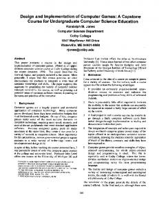
As previously mentioned, the BIAS depends on the temperature, which means that eventually, the BIAS value will differ from the value stored and it will produce a drift as in
figure 3. In this case it is necessary to restart the device to repeat the routine calibration. is given in angular rate units (°/s), the conversion to angle is done multiplying the filtered value by the sensitivity, as follows: (26) (27)
where:
(28) 150
50
0
-50 -100
0
500
1000
1500
2000
2500
3000
3500
4000
4500
Time (ms)
Figure 3. Drift error produced by the gyroscope BIAS signal
Angular rate gyroscopeY
∫
+/-
TABLE 1. ENCODER CODIFICATION FOR THE DESIGNED SCROLL. Mechanical window
Drift compensation
X position
Calibration routine
Figure 4. General block diagram for the X-axis position calculation.
IV.
C. Scroll design Normally, a mouse scroll is an electromechanical device which converts angular position or an axial movement into a digital codification. This codification allows the mouse to determine the direction and velocity of any rotation axis [14]. The performed device replaces the conventional mouse scrolling with the angle information provided by the accelerometer, as in equation (13).
In the figure 4 the blocks diagram is shown. Moving Average Filter
B. Dots Per Degree (DPD) A conventional mouse measures the resolution of the user’s movement in DPI (Dots Per Inch). It gives a relation between the user’s movement and the movement of the pointer on the screen. In the performed device, due to the angular changes produced by the user when produces motion, it is required to change the reference for that resolution. Hence, this device uses DPD (Dots Per Degree). This measurement unit relates the movement on the screen – in pixels – with the angular movement produced by the user. The lab tests gave the result that 15DPD offers the best user experience with the designed mouse.
USB
As previously mentioned, the device communication with the computer is done using USB. Taking into account the connectivity options of the USB stack, it was decided that the more appropriate option for the application was the utilization of a microcontroller with embedded USB controllers. This choice was made because of the use of USB-serial and USBparallel converters would require the design of a specific HID controller, which already exists in the embedded device: the mouse controller. Moreover, it should be mentioned that the other USB configurations are not totally independents, so that they require a microcontroller for the protocol management. Using the CCS C Compiler, it is implemented the function usb_put_packet(). This function sends a package to the computer USB port as follows: usb_put_packet(1, out_data, 4, USB_DTS_TOGGLE). Where: out_data: Is a four-element array: In the first part sends the right and left click state buttons. In the second one, it is sent the X-axis movement. In the third part, it is sent the Y-axis movement. And finally it is sent the wheel mouse state.
ANGLE BETWEEN AXIS X AND Y 80