SUBJECT TERMS Database Design and Implementation, Object Oriented
Analysis, ... database. The framework used in the design and modeling consists
of:.
NAVAL POSTGRADUATE SCHOOL MONTEREY, CALIFORNIA
THESIS DESIGN AND IMPLEMENTATION OF A DATABASE FOR AN INTEGRATED SYSTEM FOR DAILY MANAGEMENT IN AN INDUSTRIAL AND COMMERCIAL ORGANIZATION by Noureddine Trigui September 2004 Thesis Advisor: Thesis Co-Advisor:
Man-Tak Shing Doron Drusinsky
Approved for public release; distribution is unlimited
THIS PAGE INTENTIONALLY LEFT BLANK
REPORT DOCUMENTATION PAGE
Form Approved OMB No. 0704-0188
Public reporting burden for this collection of information is estimated to average 1 hour per response, including the time for reviewing instruction, searching existing data sources, gathering and maintaining the data needed, and completing and reviewing the collection of information. Send comments regarding this burden estimate or any other aspect of this collection of information, including suggestions for reducing this burden, to Washington headquarters Services, Directorate for Information Operations and Reports, 1215 Jefferson Davis Highway, Suite 1204, Arlington, VA 22202-4302, and to the Office of Management and Budget, Paperwork Reduction Project (0704-0188) Washington DC 20503. 1. AGENCY USE ONLY (Leave blank)
2. REPORT DATE 3. REPORT TYPE AND DATES COVERED September 2004 Master’s Thesis 4. TITLE AND SUBTITLE: Design and Implementation of a Database for an 5. FUNDING NUMBERS Integrated System for Daily Management in an Industrial and Commercial Organization 6. AUTHOR(S) Noureddine Trigui 7. PERFORMING ORGANIZATION NAME(S) AND ADDRESS(ES) 8. PERFORMING Naval Postgraduate School ORGANIZATION REPORT Monterey, CA 93943-5000 NUMBER 9. SPONSORING /MONITORING AGENCY NAME(S) AND ADDRESS(ES) 10. SPONSORING/MONITORING N/A AGENCY REPORT NUMBER 11. SUPPLEMENTARY NOTES The views expressed in this thesis are those of the author and do not reflect the official policy or position of the Department of Defense or the U.S. Government. 12a. DISTRIBUTION / AVAILABILITY STATEMENT 12b. DISTRIBUTION CODE Approved for public release; distribution is unlimited 13. ABSTRACT (maximum 200 words) The purpose of this research is to define a centralized database containing all necessary information related to the daily management in an industrial and commercial organization that is publicly owned and equipped with civil personality and financial autonomy. The system is composed of the following subsystems: • Subsystem “Human resource management” • Subsystem “Provisioning” • Subsystem “Financial, budgetary and accounting management” The three subsystems should be installed in a central site and at regional sites. Each site will have its own database. The central database will be supplied with the data, which come from the other sites at the end of the day or according to need via modems. It is necessary to develop a tool for remote database queries in order to accomplish this work. The platform on which the application must be executed is IBM-INFORMIX running on top of the WINDOWS operating system. The database will be a relational database. The framework used in the design and modeling consists of: • Object Oriented Analysis (OOA), which enables the development of high quality software by defining the problem structure. • The Delphi Language, which provides a robust development environment. The installation of the solution will be executed according to the following scenario: • Client/Server architecture with the object oriented development tool DELPHI. • The database will be installed on the central and regional servers. • The application will be installed on the end users’ stations. • Data access will be through an open ODBC. This software will present an integrated solution that will provide centralized and accurate data, so that data will be used to derive the right decision at the best time.
14. SUBJECT TERMS Database Design and Implementation, Object Oriented Analysis, OOA, Requirements Specification, Conceptual Model, Object Model, Delphi Language, IBM INFORMIX Database Management System, MERISE, Client Server Architecture, Use Case, Sequence Diagram, Relational Database, Entity-Relationship, Data Dictionary. 17. SECURITY CLASSIFICATION OF REPORT Unclassified
18. SECURITY CLASSIFICATION OF THIS PAGE Unclassified
NSN 7540-01-280-5500
15. NUMBER OF PAGES 149 16. PRICE CODE
19. SECURITY 20. LIMITATION CLASSIFICATION OF OF ABSTRACT ABSTRACT Unclassified UL Standard Form 298 (Rev. 2-89) Prescribed by ANSI Std. 239-18
i
THIS PAGE INTENTIONALLY LEFT BLANK
ii
Approved for public release; distribution is unlimited DESIGN AND IMPLEMENTATION OF A DATABASE FOR AN INTEGRATED SYSTEM FOR DAILY MANAGEMENT IN AN INDUSTRIAL AND COMMERCIAL ORGANIZATION Noureddine Trigui Major, Tunisian Army B.S., Faculté des Sciences Economique et de Gestion de Sfax, 1989 Submitted in partial fulfillment of the requirements for the degree of MASTER OF SCIENCE IN SOFTWARE ENGINEERING from the NAVAL POSTGRADUATE SCHOOL September 2004
Author:
Noureddine Trigui
Approved by:
Man-Tak Shing Thesis Advisor Doron Drusinsky Thesis Co-Advisor Peter Denning Chairman, Department of Computer Science
iii
THIS PAGE INTENTIONALLY LEFT BLANK
iv
ABSTRACT
The purpose of this research is to define a centralized database containing all necessary information related to the daily management in an industrial and commercial organization that is publicly owned and equipped with civil personality and financial autonomy. The system is composed of the following subsystems: •
Subsystem “Human resource management”
•
Subsystem “Provisioning”
•
Subsystem “Financial, budgetary and accounting management”
The three subsystems should be installed in a central site and at regional sites. Each site will have its own database. The central database will be supplied with the data, which come from the other sites at the end of the day or according to need via modems. It is necessary to develop a tool for remote database queries in order to accomplish this work. The platform on which the application must be executed is IBM-INFORMIX running on top of the WINDOWS operating system. The database will be a relational database. The framework used in the design and modeling consists of: •
Object Oriented Analysis (OOA), which enables the development of high quality software by defining the problem structure.
•
The Delphi Language, which provides a robust development environment.
The installation of the solution will be executed according to the following scenario: •
Client/Server architecture with the object oriented development tool DELPHI.
•
The database will be installed on the central and regional servers.
•
The application will be installed on the end users’ stations.
•
Data access will be through an open ODBC.
This software will present an integrated solution that will provide centralized and accurate data, so that data will be used to derive the right decision at the best time.
v
THIS PAGE INTENTIONALLY LEFT BLANK
vi
TABLE OF CONTENTS
I.
INTRODUCTION........................................................................................................1 A. BACKGROUND ..............................................................................................1 B. AREA OF RESEARCH/SCOPE ....................................................................1 1. Introduction to the MERISE Method and the Actual Problem ......2 a. Conceptual Level.......................................................................2 b. Organizational Level.................................................................2 c. Operational Level......................................................................2 2. Transformation to Object Oriented Method.....................................3 3. Results and Possible Improvements ...................................................4 C. METHODOLOGY ..........................................................................................4 1. Why Object Oriented Methodology ...................................................4 D. ENVIRONMENT.............................................................................................5 1. Delphi 7 .................................................................................................5 2. IBM Informix Dynamic Server (IDS 9.30) ........................................5 E. ASSUMPTIONS...............................................................................................5 F. ORGANIZATION ...........................................................................................6
II.
REQUIREMENTS SPECIFICATION......................................................................7 A. HARDWARE SPECIFICATION...................................................................8 1. Server Side............................................................................................8 2. Client Side.............................................................................................8 B. VISION AND SCOPE DOCUMENT ............................................................9 1. Business Requirements........................................................................9 a. Background, Business Opportunity, and Customer Needs .....9 b. Business Objectives and Success Criteria ..............................10 c. Business Risks .........................................................................10 2. Vision of the Solution.........................................................................10 a. Vision Statement .....................................................................10 b. Major Features........................................................................10 c. Assumptions and Dependencies .............................................11 3. Scope and Limitations .......................................................................11 a. Scope of Initial Release...........................................................11 4. Business Context ................................................................................12 a. Stakeholder Profiles................................................................12 b. Project Priorities .....................................................................13 C. SOFTWARE REQUIREMENT SPECIFICATIONS (SRS) .....................13 1. Introduction........................................................................................13 a. Purpose ....................................................................................13 b. Project Scope and Product Features ......................................14 2. Overall Description............................................................................14 a. Product Perspective.................................................................14 vii
D.
b. User Classes and Characteristics ...........................................16 c. Operating Environment ..........................................................16 d. Design and Implementation Constraints ...............................16 e. User Documentation ...............................................................16 f. Assumptions and Dependencies .............................................16 3. System Features .................................................................................17 a. Pay Processing ........................................................................17 b. Codification .............................................................................17 c. Personal Information..............................................................17 d. Attendance Processing............................................................17 e. Leave Processing.....................................................................17 f. Traveling..................................................................................18 g. Supplementary Hours .............................................................18 h. Performance Review ...............................................................18 i. Medical Expenses....................................................................18 j. Temporary Duty ......................................................................18 k. Promotions ..............................................................................19 l. Retirement Calculation ...........................................................19 m. Disciplinary Acts .....................................................................19 n. Resignation..............................................................................19 o. Education and Training .........................................................19 p. Budget Entities ........................................................................20 q. Budget Record .........................................................................20 r. Cost Project .............................................................................20 s. Suppliers ..................................................................................20 t. Suppliers Proposal ..................................................................20 u. Invoices....................................................................................20 v. Purchase Orders......................................................................20 w. Supplier Payment ....................................................................21 x. Contractor Payment ................................................................21 y. Contractor Advance ................................................................21 z. Bills ..........................................................................................21 aa. Budgetary Prevision................................................................21 bb. The Journal .............................................................................21 4. External Interface Requirements .....................................................21 a. User Interfaces ........................................................................21 b. Hardware Interfaces ...............................................................22 c. Software Interfaces .................................................................22 d. Communications Interfaces....................................................22 5. Other Nonfunctional Requirements.................................................22 a. Performance Requirements ....................................................22 b. Safety Requirements ...............................................................22 c. Security Requirements ............................................................22 d. Software Quality Attributes ....................................................23 FUNCTIONAL DECOMPOSITION DIAGRAM......................................23 viii
E. F.
USE CASES....................................................................................................25 1. Use Case Diagram ..............................................................................25 2. Use Case Glossary ..............................................................................27 DATA MODELING AND ANALYSIS........................................................28 1. Conceptual Data Model Representation (CDM).............................29 2. Data Dictionary ..................................................................................34
III.
DESIGN PHASE........................................................................................................35 A. APPLICATION ARCHITECTURE............................................................35 B. OBJECT MODEL REPRESENTATION ...................................................36 1. Independent One-to-Many Relationships........................................36 2. Dependent One-to-Many Relationships...........................................36 3. Independent Many-to-Many Relationships.....................................36 4. Independent One-to-One Relationships...........................................36 C. SEQUENCE DIAGRAM...............................................................................40 1. Sequence Diagram: Create function .................................................40 2. Sequence Diagram: Update function ................................................41 3. Sequence Diagram: Search function.................................................42 4. Sequence Diagram: Delete Function ................................................43
IV.
PROTOTYPE.............................................................................................................45 A. COMMON FUNCTIONALITIES ...............................................................45 1. How to Connect ..................................................................................45 2. Feature and Common Functionalities..............................................45 a. Menu Bar.................................................................................45 b. Status Bar ................................................................................46 c. Tools Bar .................................................................................46 d. Data Manipulation..................................................................47 B. PRESENTATION OF THE MAIN MENU.................................................48 1. Database Codification........................................................................48 a. Pay Component .......................................................................49 b. Salary Component by Function..............................................49 c. Salary Component by Category and Type..............................50 d. Salary Component by Rank ....................................................50 e. Salary Component by Function and Type .............................51 f. Salary Component for General Director................................51 g. Salary component by level and Category ...............................52 h. Percentage of Production Bonus............................................52 i. Percentage of Supplementary Hours .....................................53 j. Percentage of Per Diem ..........................................................53 k. Complete Components listing .................................................54 2. Human Resource Management ........................................................54 a. Statutory and Categorized Personnel .....................................54 b. Employee Attendance Process ................................................58 c. Employee Leave Process.........................................................58 d. Employee Per Diem Process ...................................................59 e. Employee Supplementary Hour Process................................59 ix
f. g. h. i. j. k. l. m. n. o. p. V.
Employee Production Bonus Process ....................................60 Employee Performance Review Process ................................60 Employee Medical Expenses Process.....................................61 Employee Salary Advances Process .......................................61 Employee Temporary Duty Process .......................................62 Employee Resignation Process...............................................62 Employee Retirement and Death Process ..............................63 Employee Disciplinary Actions Process .................................63 Employee Promotion Process .................................................64 Automatic Operations .............................................................64 Employee Education Process..................................................65
SUMMARY AND CONCLUSION ..........................................................................69
APPENDIX A. DATA DICTIONARY ................................................................................71 APPENDIX B. DATABASE SQL SCRIPT........................................................................79 APPENDIX C. USE CASE NARRATIVE .........................................................................91 APPENDIX D. HUMAN RESOURCE MANAGEMENT SOURCE CODE................107 LIST OF REFERENCES ....................................................................................................127 INITIAL DISTRIBUTION LIST .......................................................................................129
x
LIST OF FIGURES
Figure 1. Figure 2. Figure 3. Figure 4. Figure 5. Figure 6. Figure 7. Figure 8. Figure 9. Figure 10. Figure 11. Figure 12. Figure 13. Figure 14. Figure 15.
System Architecture...........................................................................................9 Context Diagram for Release 1.0 of the Integrated System for Daily Management Activities. ...................................................................................15 Functional Decomposition Diagram of the ISYDMA System ........................24 Human Resource Sub-System Use Case Hierarchy Diagram..........................26 Conceptual Data Model Representation (Employee Management).................31 Conceptual Data Model Representation for Education Process ......................32 Conceptual Data Model Representation for Order Payoff of Personnel..........33 Client / Server System: Distributed Data (Two Tiers) (From: [8]) .................35 Object Model Representation (Employee Management).................................37 Object Model Representation for Education Process ......................................38 Object Model Representation for Order Payoff of Personnel..........................39 Sequence Diagram for the Create Function of the System ..............................40 Sequence Diagram for the Update Function of the System.............................41 Sequence Diagram for the Search Function of the System..............................42 Sequence Diagram for the Delete Function of the System ..............................43
xi
THIS PAGE INTENTIONALLY LEFT BLANK
xii
LIST OF TABLES
Table 1. Table 2. Table 3. Table 4. Table 5. Table 6. Table 7.
Comparison of the MERISE and OMT Methods ..............................................4 Stakeholder Profiles .........................................................................................12 Project Priorities...............................................................................................13 User Classes and Characteristics .....................................................................16 Use Case Glossary ...........................................................................................28 Description of the Objects Used for the CDM (After: [16])............................30 Data Element Definition ..................................................................................77
xiii
THIS PAGE INTENTIONALLY LEFT BLANK
xiv
LIST OF ACRONYMS
AS
Assumptions
BO
Business Objectives
CI
Communication Interface
CO
Design and Implementation Constraints
DBMS
Database Management System
DE
Dependencies
DFD
Data Flow Diagram
FE
Major Features
IDS
Informix Dynamic Server
ISYDMA
Integrated System for Daily Management Activities
MDA
Model Driven Architecture
MERISE
Method for the Study and Implementation of Business Information System
OE
Operating Environment
OMT
Object Modeling Techniques
OOA
Object Oriented Analysis
PE
Performance Requirements
PRAIN
Professional Association of Industry
RI
Business Risks
SC
Success Criteria
SE
Security Requirements
SI
Software Interfaces
SRS
Software Requirement Specification
UD
User Documentation
UI
User Interfaces xv
THIS PAGE INTENTIONALLY LEFT BLANK
xvi
ACKNOWLEDGMENTS
I would like to thank everyone who helped in the completion of this thesis. I especially would like to thank my advisors Dr. Man-Tak Shing and Dr. Doron Drusinsky for all their assistance. I also wish to express a heartfelt “thanks” to all the Software Engineering professors, and in particular, Dr. Shing, Dr. Michael and Professor Riehle for their extreme patience in attempting to impart their knowledge to a foreign student trying to learn new technologies. I would like to express my undying love and gratitude to my wife, Hedgier, who has always stood by me in all my endeavors providing support and swift kick when necessary, and to my daughters Amina, Amal, and Olfa, whose mere presence is a constant reminder that I must be continuously learning. Finally, I sincerely thank all NPS staff for providing me the necessary help. Without all of your contributions this would not have been possible. Thank you.
xvii
THIS PAGE INTENTIONALLY LEFT BLANK
xviii
I. A.
INTRODUCTION
BACKGROUND The utility of databases (DB) is evident in today’s world. It is often necessary to
store and retrieve data via a database in real time. This project aims to design a centralized database that contains all relevant information of the daily management activities of the Professional Association of Industry (PRAIN) and tools for querying the database locally and remotely. Geographically, the users are distributed at many sites. Their desire to have access to the database will be met by the development of two tools, one for the server and another for the client. The server contains the database itself with all information stored in binary format. The client contains programs that allow querying and updating the database via a simple and friendly graphical user interface. The realization of this project is based on the following methodology. The analysis utilized in this research is the Object-Oriented Analysis (OOA). It is inspired by several authors such as Coad and Yourdon, Davis, Rumbaugh and others [Coad and Yourdon, 1992; Rumbaugh and Al, 1996; Davis, 1993]. The purpose of this analysis is to specify the database by using the French method “MERISE” [Gaby, 1993] in order to specify the conceptual data model (CDM). Another tool used is Power AMC 9 to draw the conceptual and the object models presented in Figures 5, 6, 7, 9, 10, and 11. This tool supports both the MERISE and OMT methods for the conceptual, physical and object models. To realize the development of the project, the author used Delphi as a development language and IBM-Informix as a Database Management System (DBMS). B.
AREA OF RESEARCH/SCOPE The majority of the Tunisian organization applied a French design methodology
that allows their teams to complete their projects successfully, within the cost and time planned. This method is called MERISE (Method for the Study and Implementation of Business Information System). It is a dynamic modeling method, which models the behavior of an information system during the analysis and design phases.
1
The MERISE method is based on the separation of the data and processes to be executed in several conceptual and physical models. This separation ensures the longevity of the model. The goal of this section is to present several rules that allow the transformation of a MERISE 1 or 2 non-object-oriented design to a MERISE 3 object-oriented design, which requires a short introduction of the MERISE method. 1.
Introduction to the MERISE Method and the Actual Problem
The first version of MERISE was introduced in 1978-1979 with the aid of several branches of the French government. By the mid-1980's, it became a standard in France and other predominantly French speaking countries in financial information system development. MERISE is a systemic method that allows for a global definition of information [1]. The first version of MERISE tried to create a proposed model from different aspects such as organizational and technical as well as the strategy of the company. This is achieved through three levels, the conceptual, organizational and operational levels. a.
Conceptual Level
The goal of this level is to model a database and make the necessary changes to the information system without modifying the organizational aspect, thereby dictating the functions of the current system. The conceptual level is comprised of the following models: •
CDM (Conceptual Data Model), equivalent to an Object/Class Diagram.
•
MCT (Conceptual Process Model); equivalent to a State Diagram. b.
Organizational Level
The goal of this level is to apply the concepts derived in the conceptual level to incorporate a time frame for the project, the scope of the project and the actors to be involved. The Organizational level is comprised of the following models: •
MOT (Organizational Process Model); equivalent to a DFD.
•
MLD (Logical Data Model) c.
Operational Level
This level will execute the implementation of the techniques presented in the previous levels. The Operational level is comprised of the following models: 2
•
MOT (Organizational Process Model)
•
PDM (Physical Data Model). In order to take into consideration the extensions and the improvement
related to the organizational and technical evolution, MERISE 2 was created. The entityrelationship model used in the first version of MERISE for the data modeling experienced several deficiencies. One group of researchers introduced an extension to the model, the concepts of generalization and specialization in order to deal with the concepts of inheritance and integrity constraints in November 1990. MERISE 2 provides the conceptual level the Data Flow Diagram (DFD) and the Conceptual Model Process Analytical (MCTA) for the process, which handles the data related to the process during the design phase, and the concepts of life cycle of an object in order to take into consideration the steps followed by an object during the life cycle. After the conceptual level, MERISE 2 takes into consideration the organizational level at which the organization, the human resources and the budget were created. For the logical level, MERISE 2 defines the user interfaces and the data distribution. Finally, the physical level remains unchanged. The third version of MERISE, OOM, dated 1992, is completely marked by object oriented concepts. 2.
Transformation to Object Oriented Method
A study was completed by a group of researchers [2] whose main goal was to design a reengineering platform for legacy systems. The group proposed a rule-based approach for a systematic object-oriented transformation of a MERISE analysis. Those rules resulted from a comparison of the MERISE method and the OMT method. Table 1 shows the similarities between the two method’s model.
3
MERISE Conceptual Data Model (CDM) Entity-relationship diagram Rule example: a type of entity becomes a class Flow graph (MCC) Actor-flow graph Rule example: an actor become a class Process Conceptual Model (MCT) MCT diagram Rule example: the initial event becomes a particular state Process Organizational Model (MOT) MOT Diagram Rule example: an operation become a process Table 1. 3.
OMT Object Model Object/Class diagram Scenario Event flow diagram Dynamic Model State diagram Functional model Data Flow diagram
Comparison of the MERISE and OMT Methods
Results and Possible Improvements
The transformation of a MERISE analysis into an objected oriented technique will improve the maintenance process and the software quality. The transformation from a MERISE analysis schema to an object-oriented analysis schema is an ongoing research, which will lead to the realization of a semi-automatic tool for this transformation. [2] C.
METHODOLOGY 1.
Why Object Oriented Methodology
Object Oriented Methodology (OOM) is a systematic development approach encouraging and facilitating re-use of software components. With this methodology, a computer system can be developed on a component basis, which enables the effective reuse of existing components and facilitates the sharing of its components by other systems. The adoption of OOM can achieve higher productivity, lower maintenance costs and better quality [3]. The keys reasons and advantages of the Object Oriented Analysis (OOA) are presented for guiding two categories of people. For the project manager, this section explains the need to encourage the team members to utilize the OOA. For a team member, this section presents one argument to use to convince responsible personnel of the importance of the OOA. Coad and Yourdon (1992) have developed the OOA of which the concepts are derived from the semantic modelisations of data and the Object Oriented languages. 4
The following are several reasons and the advantages of using the OOA.
D.
•
Better tackle the questions specific to the domain of the problem. The OOA stresses the comprehension of various domains of the problem.
•
Ameliorate the interaction between the expert domain of the problem and the analyst. The OOA organizes the analysis and the specification by utilizing organizational methods that are closest to human thinking.
•
Increase the internal coherence of analysis results. The OOA reduces the separation between the different analysis activities by treating the attributes and the methods as unified entities.
•
Clearly represent the common elements. The OOA utilizes inheritance to identify the common elements of the attributes and the methods.
•
Enhance stability when evolving software for requirement change and when constructing a similar system.
•
Promote code reuse.
ENVIRONMENT 1.
Delphi 7
Borland Delphi7 Studio is the first step for the Delphi developer in the migration from Win32 to Microsoft.NET development for the Windows platform. Delphi 7, like its highly successful predecessors, is a Win32 development environment with new Model Driven Architecture (MDA), Web application development, cross-platform features, and pre-release technology designed to assist the Delphi developer in entering the world of .NET. With the new Delphi environment, developers can also port their applications cross-platform to Linux, potentially increasing their return on investment. By integrating leading development solutions into a single easy-to-use package, Delphi 7 simplifies the application life cycle and speeds time-to-market. 2.
IBM Informix Dynamic Server (IDS 9.30)
The IBM Informix Dynamic Server continues a long standing tradition within IBM and Informix of delivering a first-in-class database engine. It combines the robustness, high performance, availability and scalability needed by today’s application. [10] E.
ASSUMPTIONS Throughout this thesis, the assumption is that the reader is familiar with object
oriented programming techniques, and has a general understanding of UML representation and the SQL language. 5
F.
ORGANIZATION This thesis is divided into five chapters. Chapter I presents the background of the
problem, the area of research, the methodology and the environment used. Chapter II describes the Requirements Analysis through use cases and the development of a conceptual model. Chapter III details the design phase. Chapter IV provides a prototype developed in the Windows environment with Delphi 7 using IBM Informix Dynamic Server 9.3 as the database. Chapter V provides a conclusion and recommendations for future work.
6
II.
REQUIREMENTS SPECIFICATION
Requirements are defined during the early stage of system development as a specification of what to implement. They are descriptions of how the systems should run, application domain information, constraints on the system’s operation, or specifications of a system’s property or attribute. The purpose of this section is to identify and document requirements for the new integrated system in a form that clearly communicates the intent of the PRAIN organization. It is necessary to recognize the importance of correct and thorough requirements specification as one of the most important parts of the design effort. The detailed specifications resulted from discussions. These requirements were established to provide enough information regarding the system to make it possible to begin contemplating the conceptual model for the software engineering effort. The primary goal of developing the Integrated System for Daily Management Activities (ISYDMA) in the PRAIN organization is to provide a capability for investigating problems using an efficient automated tool from a central or regional location. The system should provide an intuitive graphical user interface encompassing all functionality of the current ISYDMA system. In addition, it should be designed so as to provide the capability for code reuse. In order to facilitate rapid application development methods, the system must be implemented using the Informix Database and the Delphi development tool. It must be able to run on all Intel Pentium X (or compatible) platforms running Microsoft Windows 98 or any more recent operating system. Finally, to the maximum extent possible, the system should be developed to insulate it from compatibility problems associated with upgrades in operating systems, programming languages, and versions of Informix Database. The ISYDMA system must be compatible with many different types of hardware ranging from notebook and desktops on the client side, to large enterprise servers from server sites. The system must be able to process data in real-time and should provide an “adequate” level of usability based on the following hardware specifications. 7
A.
HARDWARE SPECIFICATION 1.
Server Side
•
Computer server architecture: Intel or compatible 1 GHz or higher;
•
Memory (RAM): 512 MB min;
•
Hard Disk space: 120 GB or higher;
•
Monitor: 800 X 600 or higher resolution required;
•
Mouse: Microsoft or compatible;
•
CD-ROM: required.
2.
Client Side
•
Computer CPU: Intel or compatible 233 MHz or higher;
•
Memory (RAM): 128 MB min;
•
Hard Disk space: 40 GB or higher;
•
Monitor: 800 X 600 or higher resolution required;
•
Mouse: Microsoft or compatible;
•
CD-ROM: required.
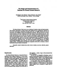
Two versions of the program are required. One is for the central site and the second for the regional sites. Specific requirements for the central version are needed. Care should be taken to provide as many opportunities as possible for code reuse.
8
Regional Site 1 Regional Site 2
Central Site
Regional Site 4 Regional Site 3
Figure 1. B.
System Architecture
VISION AND SCOPE DOCUMENT 1.
Business Requirements a.
Background, Business Opportunity, and Customer Needs
Within the framework of the implementation of its handbook of administrative, financial and technical procedures, the PRAIN proposes to realize a mission of study and data-processing applications with the following responsibilities: •
The study and design of the new data-processing application integrated in a total system;
•
The realization of the various applications of the system;
•
The installation of the various applications and assistance for new applications. The objectives of this mission are:
•
Ensure coherence between the organization and management objectives identified by its organizational charts;
•
Ameliorate the efficiency of the data-processing tools;
•
Optimize the information circuits in order to ensure better management of the resources;
•
Assure better quality services and better follow-up budgetary processes; 9
•
Facilitate communication between the various units;
•
Provides the regional sites with their own management systems;
•
Allow the central site to be centralizing and a distributor of information;
•
Develop the applications in a uniform system. b.
Business Objectives and Success Criteria
BO-1: Reduce the wait time in the manual procedures. BO-2: Increase the average effective work time by 50% for every activity. BO-3: Have a reliable information system. BO-4: Have a good archival system that will serve as system reference. SC-1: Have the majority of the employees who presently use the manual system use the automated system for managing the overall daily activities. SC-2: Achieve an increase in the satisfaction of users from the new system. c.
Business Risks
RI-1: Too few employees might use the system, reducing the return on investment from system development and changes in management operating procedures. RI-2: Some employees might be afraid to apply the new system’s procedures, which would reduce employee satisfaction with the system and possibly its usage. 2.
Vision of the Solution a.
Vision Statement
For many industrial organizations desiring an automated system to help employees manage daily activities, the ISYDMA system is a client-server application that will integrate different subsystems in order to manage human resources, provisioning, financial, budgeting, and accounting. Every organization will save time and will increase the productivity of their employees with this system. b.
Major Features
FE–1: Human resource management •
Personnel management
•
Payroll
•
Education process
FE-2: Provisioning management •
Managing cash purchase 10
•
Managing purchase orders
•
Managing markets
FE-3: Accounting management FE-4: Budget management FE-5: Finance management FE-6: Performance •
Fast Response
FE-7: Security •
Maintain privacy and data integrity. c.
Assumptions and Dependencies
AS-1: Computers and printers will be available in every unit at the central and regional sites to permit users to process the daily management activities with accurate information. AS-2: Technical staff will be available to assist all users upon implementation of the system. DE-1: If connectivity to the server is lost, it is possible to use a computer from another unit to access the database. 3.
Scope and Limitations a.
Scope of Initial Release
Features have been prioritized and scoped to available resources. Throughout this thesis, it is assumed that the reader is familiar with object oriented programming techniques as well as a general understanding of UML Notation and SQL language.
11
4.
Business Context a.
Stakeholder
Stakeholder Profiles
Major Value
Database Improved Administrator database performance and reliability, ensure the continuity of the productivity Regional interest user
Central interest user
Special Interest user
Needs to set up the system in order to have coherent information Needs to set up the system in order to collaborate with the regional sites Needs accurate information
Table 2.
Attitudes
Major Interests
Constraints
This project should not compromise existing systems nor add an administrative burden Cooperative
Security; Added Network and CPU load; Administrative overhead
Minimal impact to existing systems; Little if any ongoing maintenance activities
Minimal new technology needed; concern about transferring information Concern about having accurate information and the method of obtaining said information Concern about having accurate information in order to update the databases
Network performance and might not have technical staff support Availability of network
Cooperative
Cooperative
Stakeholder Profiles
12
Availability of data storage
b. Dimension
Project Priorities
Driver
Constraint
Degree of Freedom Release 1 planned to be available by 12/31/04, release 2 by 05/30/05; delays of approximately three weeks is acceptable
Schedule
All features scheduled for release 1.0 must be fully operational 95% of user acceptance tests must pass; all security tests must pass; compliance with corporate security standards must be demonstrated for all secure transactions
Features Quality
Projected team size is half-time project manager, two developers, and halftime tester; additional half-time developer and half-time tester will be available if necessary
Staff
Budget overrun up to 15% acceptable
Cost Table 3. C.
Project Priorities
SOFTWARE REQUIREMENT SPECIFICATIONS (SRS) 1.
Introduction a.
Purpose
This
SRS
describes
the
software
functional
and
nonfunctional
requirements for release 1.0 of the Integrated System for Daily Management Activities (ISYDMA) in PRAIN. This document is intended to be used by the members of the
13
project team implementing and verifying the correct functioning of the system. Unless otherwise noted, all requirements specified here are of high priority and committed for release 1.0. b.
Project Scope and Product Features
The ISYDMA in PRAIN will support the integration of distributed crossdisciplinary data sources into coherent knowledge bases for managing daily activities. Section B.1 provides a detailed project description and section B.2 lists the features scheduled for full or partial implementation in this release. 2.
Overall Description a.
Product Perspective
The ISYDMA in PRAIN is a new system that aims to assemble distributed cross-disciplinary data sources into a coherent knowledge base to support collaboration within the different sites. The context diagram in Figure 2 illustrates the external entities and system interfaces for release 1.0. The system is expected to evolve over several releases.
14
Figure 2.
Context Diagram for Release 1.0 of the Integrated System for Daily Management Activities.
15
b.
User Classes and Characteristics
User Classes Human Resources department
Provisioning department Accounting department Finance department
Budget department Database Manager
Characteristics The Human Resources department is responsible for the follow-up of the recruitment and attendance, promotion process, managing the personnel carrier, managing the personnel vacations, preparing personnel payroll as well as managing per diem, bonuses, advances, professional performance review, and the educational process. The provisioning system is responsible for the management of suppliers, purchase orders, invoices, and price quotations. The accounting system ensures the following functionalities: add and modify the system constants and the entries, and the management of the immobilization. The finance system closely linked to the human resource system. It is also responsible for personnel payroll, contractor payment and advances, supplier payment, credit management, and management of the central cashier. The budgetary system permits budget planning and proposal for pledging funds, the definition of the different parameters and nomenclatures, and the follow-up of the annual budget. Responsible for the security of the overall system
Table 4. c.
User Classes and Characteristics
Operating Environment
OE-1: The ISYDMA shall operate with a graphical user interface and clientserver architecture. OE-2: The ISYDMA shall operate over a secure data transmission to ensure security of personal and sensitive information. d.
Design and Implementation Constraints
CO-1: The system’s design, development, and maintenance documentation shall conform to the IEEE 1016 [5], 1074 [6], and 1219 [7] standards e.
User Documentation
UD-1: The system shall provide a help system that illustrates all system functions. f.
Assumptions and Dependencies
AS-1: The system aims to facilitate and improve the quality of the services offered. DE-1: The operation of the ISYDMA depends on the availability of the network when a query is requested from the system. DE-2: The operation of the ISYDMA depends on the performance of the database and the overall system.
16
3.
System Features a.
Pay Processing
The system shall provide a functionality that allows updating the pay components. Each component is identified by its code and designation. The property of each component and its type are obligatory and are used at the time as pay generation. The assignment of the components of the pay is automatic and occurs at the same time as the creation or updating of the statutory personal card. The amount of the component for each person is calculated based on the associated function, category, and rank. Certain component amounts are calculated based on the assigned percentage (supplementary hours, per diem, and production bonuses) b.
Codification
The system shall provide a functionality that allows creating and updating any components used for the pay module. Those components are classified by function, rank, category, and type. Classification determines the amount of the component for each person. c.
Personal Information
The system shall also provide a functionality that allows the creation and the establishment of personal information. This interface must provide two parts. One is the identification part and it contains the ID, first name, last name, photograph and main department. The second part contains information about personal, administrative, and family data as well as fixed and variable components. d.
Attendance Processing
The system shall provide a functionality that allows the introduction of personnel attendance for every month of pay. It presents the personnel ID, the number of days absent, and the type of absence, either a justified or a non justified absence. e.
Leave Processing
The system shall provide a functionality that allows the tracking of the leave process. This interface shall contain the year of the leave, personnel ID, the references of leave requests, dates of leave, type of the leave, and address during leave.
17
f.
Traveling
The system shall provide a functionality that allows the recording of the traveling done by person for each month of pay. This interface primarily contains the year of pay, the month of pay, personnel ID, type of travel (short duration or long duration), the number of nights and the amount. g.
Supplementary Hours
The system shall provide a functionality that allows the recording of the supplementary hours (overtime) done by person in each month of pay. It should contain the year and the month of pay, the personnel ID and the number of hours worked. Following the validation of the number of hours worked, the system will ascertain the hourly rate and determine the overtime rate, which depends on the personal category and type. h.
Performance Review
The system shall provide functionality related to the performance review and absences during the six-month period. Two types of performance reviews are professional and production bonuses. The interface should contain the year of the pay, the review period 1 or 2 consisting of six months each, personnel ID and the number of days absent. i.
Medical Expenses
The system shall provide a functionality that allows the recording of the medical expenses that should be refunded. The act of recording is completed from the invoice provided by the insurance company. The interface should contain the year and the month of the pay, the insurance invoice number, the invoice’s total amount, the affiliation insurance number, personnel ID, name and the amount to be refunded. j.
Temporary Duty
The system shall provide a functionality that allows the recording, modification, searching and deletion of the information related to the temporary duty to other establishment. This interface should deal with the following temporary duty information: the year, the reference number, date approved, personnel ID, name, type duty (in the same organization or to another organization), beginning date, end date, and assigned department. 18
k.
Promotions
The system shall provide a functionality that allows the recording, modification, searching and deletion of the information related to personnel promotions. This interface should provide the following information: the type of operation (promotion to a higher level, reclassification, promotion in rank or function), the decision identification, date of the decision, personnel ID, name, old position, new position (rank, function, category, the amount of the basic wage, and date beginning the new position). l.
Retirement Calculation
The system shall provide a functionality that allows the recording, modification, searching and deletion of the information related to the retirement or death of the person. This information is the year of the retirement decision or death notice, the decision identification or death notice, date, personnel ID, name, type (retirement or death), end date of work and personnel address for retirement. m.
Disciplinary Acts
The system shall provide a functionality that allows the recording, modification, searching and deletion of the information related to disciplinary acts. This interface should contain the following information: year of the disciplinary decision, the decision identification, date of the decision, personnel ID, name, type of discipline, and reason, the number of days, beginning date, and end date of the disciplinary act. n.
Resignation
The system shall provide a functionality that allows the recording, modification, searching and deletion of the information related to the resignation of the personnel. This interface should contain the following information: year of the request, reference number, date of the request, personnel ID, name, reason for resigning, and the last date of employment. o.
Education and Training
The system shall provide a functionality that allows the creating, modification, searching and deletion of the information related to the schedule, planning the training courses, calculating the cost of the training, and record the list of the trainees.
19
p.
Budget Entities
The system shall provide a functionality that allows the correction, modification, searching and deletion of the information related to the budget assigned to a project, regional direction, a local coordination and a committee of development. This interface should contain the following information: local coordination code, year, project code, action code, organization code, source code of financing, title, amount of prevision budget, and date of final budget approval. q.
Budget Record
The system shall provide a functionality that allows the creation, modification, searching, deletion, and editing of a budgetary record from a proposal for pledging funds. It also allows the validation of the budget after signature. r.
Cost Project
The system shall provide a functionality that allows the correction, modification, searching, and deletion of the prevision cost of the project. s.
Suppliers
The system shall provide a functionality that allows the creation, modification, searching and deletion of the suppliers’ record in order to have a data bank on the suppliers by branch of industry. Also, the functionality should allow the translation of the information from French into Arabic. t.
Suppliers Proposal
The system shall provide a functionality that allows the introduction, modification, searching, deletion, and editing of the information provided by the suppliers’ proposal as well as generation of a list comparing the presented proposal to the request for quotation after verifying the imposed criteria. u.
Invoices
The system shall provide a functionality that allows the creation, modification, searching, deletion, and editing of the invoices. v.
Purchase Orders
The system shall provide a functionality that allows the creation, modification, searching, deletion, and editing of the orders provided by the organization to be revised by the supplier. 20
w.
Supplier Payment
The system shall provide a functionality that allows the creation, modification, searching, deletion, and editing of the payment for the profit of the suppliers after providing the totality of the merchandize requested by the orders. x.
Contractor Payment
The system shall provide a functionality that allows the creation, modification, searching, deletion, and editing of the records of the payments to the contractor who has signed a contract with the organization. y.
Contractor Advance
The system shall provide a functionality that allows the follow up of the advances presented to the contractor for a project. z.
Bills
The system shall provide a functionality that allows the follow up of the payment of bills. aa.
Budgetary Prevision
The system shall provide a functionality that allows the creation, modification, searching, deletion, and editing of the budgetary prevision for the current year from a proposal presented to the community for budget approval. bb.
The Journal
The system shall provide a functionality that allows the follow up of the daily accounting actions. 4.
External Interface Requirements a.
User Interfaces
UI-1: The ISYDMA System screen displays shall conform to the existing manual forms in order to facilitate the exploitation of those documents UI-2: The system shall provide a link to explain how to use that screen. UI-3: The graphical interface shall permit complete navigation and a research information database search selection only using the keyboard, in addition to using mouse and keyboard combinations. UI-4: The ISYDMA system shall provide a standard and uniform screen that contains a menu bar, tool bar and status bar. The menu bar contains some standard menu options such as file, edit, and selection. The status bar should contain the actual selection and the actual user. The tool bar should group the primary operations that a user is authorized to execute (add, 21
update, record, cancel, delete, research, clear, result, first, previous, next, last and close). b.
Hardware Interfaces
No hardware interfaces have been identified. c.
Software Interfaces
SI-1: The ISYDMA system shall transmit information to the social security department in order to update their database concerning retirement. SI-2: The ISYDMA system shall transmit information to the central bank in order to update the accounts. SI-3: The ISYDMA system shall provide an interface that allows for the transfer of information between different systems. d.
Communications Interfaces
CI-1: The ISYDMA system shall send an email message to the external systems to inform any database status change such as software, hardware upgrades, system migration and maintenance of the ISYDMA system. 5.
Other Nonfunctional Requirements a.
Performance Requirements
PE-1: The system shall accommodate 300 users during the peak usage time window of 8:00 am to 10:00 am local time, with an estimated average session duration of 50 minutes. PE-2: All screens containing graphical information shall be fully downloadable in no more than 50 seconds over a 56 KBps modem connection at no less than 90% of the attempts. PE-3: Responses to queries shall take no longer than 20 seconds to load onto the screen after the user submits the query. PE-4: The system shall display confirmation messages to users within four seconds after the user submits information to the system. b.
Safety Requirements
No safety requirements have been identified. c.
Security Requirements
SE-1: All network transactions that involve financial and personnel privacy information or personally identifiable information shall be encrypted. SE-2: Users shall be required to log in to the ISYDMA system for all operations prior to viewing any of the information. SE-3: Users will be allowed only one login ID and in addition, passwords chosen must consist of at least eight alphanumeric distinct characters.
22
SE-4: The system shall permit only ISYDMA system administrators who are on the list of authorized administrators to create or edit User profiles and the user personnel privacy database. SE-5: The system shall permit users to view only their own searched records, and not the searched information performed by other users. d.
D.
Software Quality Attributes
Availability-1:
The ISYDMA System shall be available to users 99.9% of the time between 5:00 am and midnight local time
Robustness-1:
If the connection between the user and the system is broken prior to the completion of a search on the systems, the ISYDMA system shall enable the user to recover an incomplete search.
FUNCTIONAL DECOMPOSITION DIAGRAM The decomposition diagram shows the top-down functional decomposition or
structure of the system. It also provides the beginnings of an outline for drawing the data flow diagrams.
23
Figure 3.
Functional Decomposition Diagram of the ISYDMA System 24
E.
USE CASES 1.
Use Case Diagram
Use case modeling was originally conceived by Dr. Ivar Jacobson in 1986 and gained popularity after he published his book, Object-Oriented Software Engineering, in 1992. Dr. Jacobson used use-case modeling as the framework for his objectory methodology, which he successfully used for developing an object oriented information system. Use case modeling has proved to be a valuable tool in meeting the challenges of determining what a system is required to do from a user and stakeholder perspective, and it is now widely recognized as a best practice for the defining, documenting and understanding of an information system’s functional requirements [8]. The use cases establish the desired behavior of the system for verifying and validating the system architecture. Many use cases for the ISYDMA system is identified, each corresponding to different functionality. This thesis presents only use cases related to the management of the human resource sub-system as summarized in Figure 4. Detailed description of each use case is presented in Appendix C. Only the major steps that occur most of the time are included in those use cases. Also presented are some preconditions, post-conditions and exceptions that must be handled by the system.
25
Figure 4.
Human Resource Sub-System Use Case Hierarchy Diagram
26
2.
Use Case Glossary
Use-case Name
Use-case Description
Create pay component
This use case describes the events of pay section for establishing a new pay component that will serve as a key part for calculation of employee payment. Create employee This use case describes the events of Record personnel and training section for creating an employee record which is similar for the three types of employee (Statutory employee, Workman employee, agriculture employee). The Employee record is composed of several parts. The first part concerns the identification information, the second the administrative information, and the last the family information. Create employee This use case describes the events of a attendance record personnel section creating a record related to the absence of an employee. Absence can be classified as justified or not justified. Search employee This use case describes the events of a disciplinary sanction personnel section for searching a record record related to disciplinary acts. Update employee This use case describes the events of a temporary duty record personnel section for creating a record related to the temporary duty record. The temporary duty record can be in another organization or in another department of the same organization. Update employee This use case describes the events of a production bonus personnel section for updating the record information related to production bonuses. The production bonuses are calculated once every three months. Search employee This use case describes the events of resignation record personnel section for searching a record related to an employee’s resignation. Delete employee This use case describes the events of a educational record personnel section for deleting a record containing the different training classes that an employee had attended. The training section can be organized into an internal department or external organization. Create employee This use case describes the events of a traveling record personnel section for creating a record containing the necessary information for travel payments done by an employee during the actual month.
27
Participating Actors and Roles - Pay section (primary business) - Personnel section (primary business) - Training section
- Personnel section (primary business) - Personnel section (primary business) - Personnel section (primary business)
- Personnel section (primary business) - Finance section - Personnel section (primary business) - Finance section - Personnel section (primary business) - Training section
- Personnel section (primary business) - Finance section
Use-case Name
Use-case Description
Participating Actors and Roles
Search employee promotion record
This use case describes the events of a personnel section for searching a record related to the promotion of an employee. An employee’s promotion must satisfy certain conditions. There are two types of promotion: rank promotion and category promotion. Each one affects the pay components. This use case describes the events of a personnel section for searching a record for retirement and a record upon the death of an employee. Those records affect the pay component. This use case describes the events of a personnel section for creating a record for medical expenses. This use case describes the events of a personnel section for creating a record for an employee’s leave time. There are many types of leave: annual leave, advance leave, family leave, sick leave, leave without pay, maternity leave. This use case describes the events of a personnel section for updating a record for the supplementary hour record. Every employee has a maximum number of supplementary hours per month. The amount of money allowed for one supplementary hour depends on the rank and the type of employee. This use case describes the events of a personnel section for creating a record for grouping all the components and necessary information to calculate the salary of an employee. The pay calculation is executed every month, and should be started by the second week of the actual month.
- Personnel section (primary business) - Finance section
Search employee retirement or death record Create medical expenses record Create employee leave process
Update employee supplementary hours record
Process pay calculation
Table 5. F.
- Personnel section (primary business) - Finance section - Personnel section (primary business) - Medical section - Personnel section (primary business)
- Personnel section (primary business) - Finance section
- Personnel section (primary business) - Finance section
Use Case Glossary
DATA MODELING AND ANALYSIS Systems models play an important role in systems development. Data modeling is
a technique for defining business requirements for a database. Data modeling is often called database modeling because a data model is eventually implemented as a database.
28
The data model is a conceptual representation of the data structures required by a database. The data structures include the data objects, the associations between data objects, and the rules, which govern operations on the objects. As the name implies, the data model focuses on what data is required and how it should be organized rather than what operations will be performed on the data. A data model is independent of hardware or software constraints. Rather than trying to represent the data, as a database would see it, the data model focuses on representing the data as the user sees it in the “real world”. It serves as a bridge between the concepts that compose real-world events and processes and the physical representation of those concepts in a database. There are two major methodologies used to create a data model: the Entity-Relationship (ER) approach and the Object Model. This thesis uses the Entity-Relationship approach. [8] The data model obtains its inputs from the planning and analysis stage. The modeler, along with analysts, collects information about the requirements of the database by reviewing existing documentation and interviewing end-users. 1.
Conceptual Data Model Representation (CDM)
A CDM represents the overall logical structure of a database, which is independent of any software or data storage structure. A conceptual model often contains data objects not yet implemented in the physical database. It gives a formal representation of the data needed to run an enterprise or a business activity. The CDM makes it possible: •
Represent the organization of data in a graphical format to create Entity Relationship Diagrams (ERD)
•
Verify the validity of data design
•
Generate a Physical Data Model (PDM), which specifies the physical implementation of the database
•
Generate an Object-Oriented Model (OOM), which specifies an object representation of the CDM using the UML standard
•
Generate a Conceptual Data Model (CDM), to create another model version in order to represent different design stages
29
A CDM represents the interaction of the following objects: Object
Tool Description
Domain
--
Set of values for which a data item is valid
Data item
--
Elementary piece of information Person, place, thing, or concept that has characteristics of interest to the enterprise and information to be stored
Entity Entity attribute
--
Elementary piece of information attached to an entity
Identifier
--
Entity attribute, or a combination of entity attributes, whose values uniquely identify each occurrence of the entity
Relationship
Named connection or relation between entities (Entity Relationship (ER) modeling methodology)
Inheritance
Special relationship that defines an entity as a special case of a more general entity
Association
Named connection or association between entities (MERISE modeling methodology)
Association link
Link that connects an association to an entity and the definition of the cardinality an entity has relative to another
Table 6.
Description of the Objects Used for the CDM (After: [16])
The Conceptual Data Model for the human resource sub-system is divided into three parts. The first part concerns Employee Management (Figure 5). The second part concerns the Follow up of Education (Figure 6). The third part concerns the Order of payoff of personnel (Figure 7). The data model has two outputs. The first is an entityrelationship diagram, which represents the data structures in a pictorial form (Figures 5, 6, 7). The second component is a data dictionary that provides the detail required by the database developer to construct the physical database.
30
Notation criteria code criteria A2 Leave ref vacation request I 0,n 1,1
Assigned note assigned note DC5,2
Detach year decision A4 ref decision I
0,n ask
Notation record
1,1
Year Notation N4 Number half year A10 detached 1,1
0,n Employee
maintain
0,n Employee ID A5
Rank 0,n
Rank A4
0,n
0,n
0,n
0,n
resignate
1,1
0,n
Resignation gets
receive support
retire
1,1
1,1
0,n
1,1
Decision
Disciplinary sanction
yesr decision A4 ref decision I
Year decision sanction A4 Number decision sanction I
1,1
Year decision resignation A4 ref decision resignation I
Retirement and death Year record retirement or death A4 record number I
1,1 have has
1,n
0,n Level
Type sanction
Code level A2
Code sanction A2
Figure 5.
Conceptual Data Model Representation (Employee Management)
31
Employee Employee ID A5 0,n
0,n
Attendance
Axis of education
Start hour End hour
Axis number A5 register 0,n
education result 0,n
follow
Education session Year session A Number session I
1,1
1,1 contain
1,1 Education plan 0,n
0,n present
Plan reference A10
Education Year education A4 ref education I
1,1
0,n
0,n
process
0,n gives
Theme education Code theme A4
hours number
1,n Organism of education instructor A10
Figure 6.
Conceptual Data Model Representation for Education Process
32
Unit Code unit A3 Instruction level 0,n
Position
1,1
Bank
Code diploma A3
Code position A3
a30
Code level of instruction A3
Diploma
Code bank A4
0,n
0,n
0,n
0,n
Rank Rank A4
Sub unit
Component/rank
0,n
Amount component MN
Code sub unit A2
1,1
0,n
a5
a20
keep
0,n
a11
0,n Category
Projet Code projet A2
affected 0,n
obtain
a29
0,n
pay
0,n
Speciality
Arabic code category A2
code speciality A3 Function category 0,n
Amount of 1/3 displacement MN
promoted a12
Insurer code insurer A2
0,n
0,n
Code function A3
a13
0,n
0,1 0,1 0,10,1 1,1 1,1
Child
0,1
0,1
0,1 0,n
1,1
0,1
Employee Employee ID A5
0,n
Advance Month advance A2 Amount of the advance MN
composante/personnel
0,n
montant composante date début date fin type opération
0,n 0,n
0,n
0,n 0,n
amount component MN
0,n
Assoc _1382
1,1
a14
Number child N2
Component by function
Function
0,n
MN D D A1
0,n
0,n Component
0,n
Code component A4
1,n 0,n
Advance aid and school Year advance A4 Type advance A2 Production bonus by employee received grade Abscence number Amount of advance Amount bonus
DC5,2 DC6,2 MN MN
Suplementary hours
Pay journal
Number of hour DC5,2
Generated amount MN
Displacement Number of tier N2 Amount displacement MN 1,n Absence Production bonuses Year bonus A4 Type of bonus A1 Number of the quarter N1
Figure 7.
type absence A1 Number of day absence N2
History personnel military situation unique salary Echelon categoty function Statut rank level Position Profit of a function car profit of lodging Number of children Number of children IRPP
A1 A1 A1 A2 A3 A1 A4 A2 A3 A1 A1 N2 N2
1,n
1,n 1,n
1,n
Year and month of pay 1,n
Year pay A4 Month pay A2
Conceptual Data Model Representation for Order Payoff of Personnel 33
2.
Data Dictionary
The data dictionary encompasses the whole organization, a part of the organization or a database. In its simplest form, the data dictionary is only a collection of data element definitions, according to the descriptions that follow. A more advanced data dictionary contains the database schema with reference keys, while a more advanced data dictionary contains the entity-relationship model of the data elements or objects. The term “data element” used below is the same concept as a “data object” or “object” in some database texts. •
Data element name: commonly agreed, unique data element name from the application domain. This is the actual name of this data element.
•
Short description: description of the element in the application domain.
•
Field name(s): Field names are the names used for this element in computer programs and database schemas. These are the technical names, often limited by the programming languages and systems.
•
Code format: Data type (characters, numeric, etc.), size and, if needed, special representation. Common programming language notation, input masks, etc. can be used.
•
Default value: Data element may have a default value. The default value may be a variable, such as a current date and time of day.
Appendix A shows the list of data collected for the human resource sub system. Appendix B shows the database schema.
34
III. A.
DESIGN PHASE
APPLICATION ARCHITECTURE The purpose of the first design task is to specify the application architecture that
defines the technologies to be used by one, many, or all information systems in terms of their data, processes, interfaces and network components. Thus, designing the application architecture involves considering network technologies and making decisions on the systems’ data. Processes and interfaces are distributed among the business locations. This task is accomplished by analyzing the data model and process models initially created during requirements analysis. The following figure shows the architecture used for the ISYDMA system (client/server system) in which the data and data manipulation layers are placed on servers and others layers are placed on clients, also called two-tier client/server computing.
Figure 8.
Client / Server System: Distributed Data (Two Tiers) (From: [8]) 35
B.
OBJECT MODEL REPRESENTATION In object oriented analysis, the emphasis is on identifying the objects that
represent actual data within the business domain. These objects are called entity objects. The transformation from the Conceptual Data Model to the Object Model is an automated process realized by PowerAMC used for representing the Conceptual Data Model (Figures 5, 6, 7). When generating an Object Oriented Model (OOM) from a CDM, PowerAMC converts CDM objects into specified object language objects as follows: CDM Objects
Generated object in an OOM
Entity
Class
Attribute
Attribute
Association
Relationship or association
Binary association with attributes Association class Inheritance
Generalization
The rules applied for this transformation are as follows. 1.
Independent One-to-Many Relationships
In independent one-to-many relationships, the primary identifier of the entity on the one side of the relationship becomes a: •
Primary key in the entity on the one side of the relationship
•
Foreign key in the entity on the many side of the relationship
2.
Dependent One-to-Many Relationships
In dependent relationships, the primary identifier of the nondependent entity becomes a primary/foreign key in the dependent entity. 3.
Independent Many-to-Many Relationships
In independent many-to-many relationships, the primary identifiers of both entities migrate to a join entity as primary/foreign keys. 4.
Independent One-to-One Relationships
In independent one-to-one relationships, the primary identifier of one entity migrates to the other generated entity as a foreign key.
36
Notation criteria + code criteria + arabic label ... ... Leave Assigned notation
+ reference request + Vacation type ... ...
0..*
+ assigned note
0..* 0..*
Notation record
Detach
+ Year Notation + Number half year ... ...
+ Year decision + ref decision ... ...
0..*
0..*
Resignation 1..1
1..1 Rank
+ Year decision resignation + ref decision resignation ... ...
1..1
Employee
+ Rank + Arabic label ... ...
+ Employee number + Arabic firstname ... ... + + + +
1..1
CreateEmployee () UpdateEmployee () SelectEmployee () DeleteEmployee ()
0..*
0..*
1..1
0..*
1..1 0..*
Disciplinary sanction + Year decision sanction + Number decision sanction ... ...
1..1
0..*
1..*
Decision + Year decision + ref decision ... ...
0..* Retirement and death + Year card retirement or death + Card number ... ...
Figure 9.
1..1 Type sanction + Code sanction + Label sanction
Object Model Representation (Employee Management)
Note: Underlined attributes denote the keys of the data items.
37
Attendance + Start hour + End hour
Education session
Employee
+ Year session + Number session ... ...
0..*
0..* 0..*
Axis of education
+ Employee number + Arabic firstname ... ...
+ Axis number + Axis label
+ CreateEmployee () : U d t E l ()
0..*
1..1
0..*
Register + education result
1..1 Theme education
0..*
+ Code theme + Label theme
Education plan + Plan reference + Year plan ... ... 1..1 1..1
0..*
Education
0..*
+ Year education + ref education ... ...
Gives + hours number 1..*
0..* Organism of education + instructor + Activity instructor ... ...
Figure 10.
Object Model Representation for Education Process
38
Unit + Code unit + Arabic label unit ... ... Bank
1..1
+ Code bank + Arabic label bank ... ...
Position + Code position + Arabic label position ... ...
0..* Sub unit
Category + Arabic code category + French code category
0..1
+ Code sub unit + Arabic label sub unit ... ...
Instruction level
Diploma
1..1
1..1
0..1
Projet
1..1
+ Code level of instruction + Arabic label level instruction ... ...
+ Code diploma + Arabic label diploma ... ...
0..*
0..1
+ Code projet + arabic label ... ...
0..* Rank
0..1
Speciality + code spécialité + Libellé en arabe ... ...
Function category
+ Rank + Arabic label ... ...
+ Amount of 1/3 displacement
0..*
1..1 0..1
0..* Insurer + code assureur + arabic label ... ...
0..* 0..*
0..1
Child
Advance aid and school
CreateEmployee () UpdateEmployee () SelectEmployee () DeleteEmployee ()
Function 0..1
+ Code function + Arabic label function ... ... 0..*
0..* : int : int : int : int
0..*
0..*
Component 0..*
0..*
1..*
0..*
+ Year advance + Type advance
0..*
0..*
0..*
+ Employee number + Arabic firstname ... ...
+ 1..1 + + 1..* +
0..*
0..* Employee
0..*
+ Number child + Name child ... ...
Component/rank + Amount component
0..*
0..*
1..* 1..*
0..*
1..*
1..*
+ Code component + Arabic label component ... ...
Composante_personnel 0..*
+ montant composante + date début ... ...
Advance + Month advance + Amount of the advance
1..*
Component by function + amount component
Suplementary hours
0..1
+ Number of hour Pay _jour
0..* Production bonus by employee
0..1
Production bonuses
+ received grade + Abscence number ... ...
+ Year bonus + Type of bonus ... ...
+ Generated amount
0..1 Historique personnel + military situation + unique salary ... ...
Component history + Code rule of calculation
Absence + type absence + Number of day absence
Displacement + Number of tier + Amount displacement
0..* 0..*
0..*
0..*
0..*
Year and month of pay + Year pay + Month pay
Figure 11.
0..*
Object Model Representation for Order Payoff of Personnel 39
C.
SEQUENCE DIAGRAM The sequence diagram depicts the objects and classes involved in the scenario and
the sequence of messages exchanged between the objects needed to execute the functionality of the system. It can be used to derive the testable user interface requirement. 1.
Sequence Diagram: Create function
The sequence diagram in Figure 12 shows the process for creating data records. An instance of the User class invokes a method on the Identification module process called ChooseModule(). The return value from the actual object is then used to instantiate an instance of Module object. A method called AccessModule() is then invoked on the new instance. This instantiates an instance of Display Process and invokes a method called DisplayForm(). The User Class invokes a new method on the Create Process that returns a message for authorizing the add record. After receiving the authorization, the User invokes a method in the Control Process called EnterData(). The control is actually requested from this object. If the input data are valid, then the record is created and the Validation Process invokes a method on the Add Process called AddRecord(). Finally, a message confirming the Add record is sent to the user.
User
Id_ Module _Pro
Module
Display_Pro
Create_Pro
Control_Pro
Validate_Pro
Add_Pro
ChooseModule() AccessModele() DisplayForm() Form Displayed CreateRecord()
Authorized to Create Record
Enterdata() Data Controled Enterdata()
AddRecord() Data Stored
* [Until done]
Figure 12.
Sequence Diagram for the Create Function of the System 40
2.
Sequence Diagram: Update function
The sequence diagram in Figure 13 shows the process for updating data records. An instance of the User class invokes a method on the Identification module process called ChooseModule(). The return value from the actual object is then used to instantiate an instance of Module object. A method called AccessModule() is then invoked on the new instance. This instantiates an instance of Display Process and invokes a method called DisplayForm(). The User Class invokes a new method on the Update Process that returns a message for authorizing the Update record. After receiving the authorization, the User invokes a method in the Control Process called EnterData(). The control process invokes a method called SearchData() that allows searching the entered information. If the input data are found, then a message Data Found is sent to the User. The User class invokes a new method on the Update process called UpdateData(). The control is actually requested from this object. If the input data are valid then the record is updated and the Validation Process invokes a method on the Record Process called UpdateRecord(). Finally, a message confirming the Update record is sent to the user.
User
Id_module_pro
Module
Display_Pro
Update_Pro
Control_Pro
Search_Pro
Validate_Pro
Record_Pro
ChooseModule() AccessModele() DisplayForm() Form Displayed UpdateRecord() Authorized to Update Record
Enterdata() SearchData() Data Found
UpdateData() Data Updated Validate() UpdateRecord() Data Updated * [Until done]
Figure 13.
Sequence Diagram for the Update Function of the System 41
3.
Sequence Diagram: Search function
The sequence diagram in Figure 14 shows the process for searching data records. An instance of the User class invokes a method on the Identification module process called ChooseModule(). The return value from the actual object is then used to instantiate an instance of Module object. A method called AccessModule() is then invoked on the new instance. This instantiates an instance of Display Process and invokes a method called DisplayForm(). The User Class invokes a new method on the Search Process that returns a message for authorizing the Search record. After receiving the authorization the User invokes a method in the Control Process called EnterData(). The control process invokes a method called SearchData() that allows searching the entered information. If the input data are found, then the search data process invokes a method on the display data process called Display(). Finally, a message confirming the Update record is sent to the user.
Figure 14.
Sequence Diagram for the Search Function of the System 42
4.
Sequence Diagram: Delete Function
The sequence diagram in Figure 15 shows the process for delete data records. An instance of the User class invokes a method on the Identification module process called ChooseModule(). The return value from the actual object is then used to instantiate an instance of Module object. A method called AccessModule() is then invoked on the new instance. This instantiates an instance of Display Process and invokes a method called DisplayForm(). The User Class invokes a new method on the Delete Process that returns a message for authorizing the Delete record. After receiving the authorization the User invokes a method in the Control Process called EnterData(). The control process invokes a method called SearchData() that allows searching the entered information. If the input data are found then a message Data Found is sent to the User. The User invokes a method on the Delete process called DeleteData(). A Message Data temporary deleted is sent to the user. The Validation Process invokes a method on the Record Process called DeleteRecord(). Finally, a message confirming the Delete record is sent to the user.
Figure 15.
Sequence Diagram for the Delete Function of the System 43
THIS PAGE INTENTIONALLY LEFT BLANK
44
IV. A.
PROTOTYPE
COMMON FUNCTIONALITIES 1.
How to Connect
When the user starts the application, it is necessary to connect the system to the authorized modules.
The process begins with File/Connect in order to access the
functionalities of the system. The following screen appears. The user types in the user ID and password.
2.
Feature and Common Functionalities
The model presents a standard screen for the entire system composed of the following features: •
Menu bar
•
Status bar
•
Tools bar
•
One or many child window a.
Menu Bar
The menu bar has the standard menu options such as File and Tools. Many other functions are available depending on the selected module. (1)
File Menu.
45
Connect
Identify user
Disconnect
Leave the active connection for the database
Printer configuration
Allow the standard window for printer configuration to open
Exit
Allow existing the module (2)
Tools Menu.
-
Cut
+X
It is the standard Cut functionality
-
Copy
+C
It is the standard Copy functionality
-
Paste +V
It is the standard Paste functionality
b.
Status Bar
The Main window has a state bar on the bottom that indicates the actual selection and the connected user
c.
Tools Bar
On the top and under the menu bar, the tools bar groups a set of symbols or icons representing the different operations that a user can utilize by simply clicking with the mouse
Allows the execution of search with specified criteria
Allows deletion of search criteria
Allows introduction of a criteria
Allows input of information
selection Go to the last record in the active
Go to the Next record in the active
table
table 46
Go to the previous record in the active table
Go to the First record in the active table
Allows addition of a record to the active table
Allows deletion of a record from the active table
Allows updating a record in the active table
Allows saving the active record
Allows showing the selected record in list format
Allows canceling input data d.
Data Manipulation (1)
Select Data. The select action is the first operation done
before searching, updating, deleting and editing any information. Before manipulating or processing data, it is necessary to select a set of data that the process will conduct. In order to select data, it is necessary to display the search screen and present the criteria of search. The symbols that can be introduced for a search of criteria can be the following. (=,>,=,'1' then BTNlistClick(BTNlist) else BTNselClick(BTNsel); end; end; procedure Tfrm_maingrh.bib_DBNavigatorClick(Sender: TObject; Button: TNavigateBtn); begin case Button of nbfirst :begin BTN_SEPremier.enabled:=false; BTN_SEPrecedent.enabled:=false; BTN_SESuivant.enabled:=true; BTN_SEDernier.enabled:=true; end; nblast :begin BTN_SEPremier.enabled:=true; BTN_SEPrecedent.enabled:=true; BTN_SESuivant.enabled:=false; BTN_SEDernier.enabled:=false; end; nbNext :begin BTN_SEPremier.enabled:=true; BTN_SEPrecedent.enabled:=true; BTN_SESuivant.enabled:=true; BTN_SEDernier.enabled:=true; end; nbPrior :begin BTN_SEPremier.enabled:=true; BTN_SEPrecedent.enabled:=true; BTN_SESuivant.enabled:=true; BTN_SEDernier.enabled:=true; end; end; naviguer; end; procedure Tfrm_maingrh.BTNnouvClick(Sender: TObject); begin flag_insert:=0; if bib_dbnavigator1.datasourceNil then begin bib_dbnavigator1.BtnClick(Nbinsert); end; end; procedure Tfrm_maingrh.BTNsuppClick(Sender: TObject); begin if bib_DBNavigator2.datasourceNil then begin bib_DBNavigator2.BtnClick(Nbdelete); end;
113
end; procedure Tfrm_maingrh.BTNmodfClick(Sender: TObject); begin flag_insert:=0; if bib_DBNavigator3.datasourceNil then begin bib_DBNavigator3.BtnClick(Nbedit); end; end; procedure Tfrm_maingrh.BTNvalidClick(Sender: TObject); begin if bib_DBNavigator3.datasourceNil then if (bib_DBNavigator3.datasource.dataset.state=dsInsert) or (bib_DBNavigator3.datasource.dataset.state=dsEdit) then bib_DBNavigator3.BtnClick(Nbpost); end; procedure Tfrm_maingrh.BTNannulClick(Sender: TObject); begin if bib_DBNavigator3.datasourceNil then if (bib_DBNavigator3.datasource.dataset.state=dsInsert) or (bib_DBNavigator3.datasource.dataset.state=dsEdit) then bib_DBNavigator3.BtnClick(Nbcancel); end; procedure Tfrm_maingrh.BTN_SEPremierClick(Sender: TObject); begin if bib_dbnavigator.datasourceNil then begin bib_dbnavigator.BtnClick(Nbfirst); BTN_SEPrecedent.enabled:=false; BTN_SEPremier.enabled:=false; end; end; procedure Tfrm_maingrh.BTN_SEPrecedentClick(Sender: TObject); begin if bib_dbnavigator.datasourceNil then begin bib_dbnavigator.BtnClick(Nbprior); if bib_dbnavigator.datasource.dataset.bof then begin BTN_SEPrecedent.enabled:=false; BTN_SEPremier.enabled:=false; BTN_SESuivant.enabled:=true; BTN_SEDernier.enabled:=true; end; end; end; procedure Tfrm_maingrh.BTN_SESuivantClick(Sender: TObject); begin if bib_dbnavigator.datasourceNil then begin
114
bib_dbnavigator.BtnClick(Nbnext); if bib_dbnavigator.datasource.dataset.eof then begin BTN_SEPremier.enabled:=true; BTN_SEPrecedent.enabled:=true; BTN_SESuivant.enabled:=false; BTN_SEDernier.enabled:=false; end; end; end; procedure Tfrm_maingrh.BTN_SEDernierClick(Sender: TObject); begin if bib_dbnavigator.datasourceNil then begin bib_dbnavigator.BtnClick(Nblast); BTN_SEPremier.enabled:=true; BTN_SEPrecedent.enabled:=true; BTN_SESuivant.enabled:=false; BTN_SEDernier.enabled:=false; end; end; procedure Tfrm_maingrh.BTNcouperClick(Sender: TObject); begin if ActiveMdiChild.activecontrol is TDBEdit then TDBEdit(ActiveMdiChild.activecontrol).cuttoclipboard; if ActiveMdiChild.activecontrol is TEdit then TEdit(ActiveMdiChild.activecontrol).cuttoclipboard; end; procedure Tfrm_maingrh.BTNcopierClick(Sender: TObject); begin if ActiveMdiChild.activecontrol is TDBEdit then TDBEdit(ActiveMdiChild.activecontrol).CopyToClipboard; if ActiveMdiChild.activecontrol is TEdit then TEdit(ActiveMdiChild.activecontrol).CopyToClipboard; end; procedure Tfrm_maingrh.BTNcollerClick(Sender: TObject); begin if ActiveMdiChild.activecontrol is TDBEdit then TDBEdit(ActiveMdiChild.activecontrol).Pastefromclipboard; if ActiveMdiChild.activecontrol is TEdit then TEdit(ActiveMdiChild.activecontrol).PastefromClipboard; end; procedure Tfrm_maingrh.BTNsaisClick(Sender: TObject); begin with frm_maingrh do begin DBgrh.DerRech:= DBgrh.DerForm;
115
case DBgrh.DerRech of C_PERSONNE : frm_PERSONNE.NBPERSONNE.PageIndex :=0; C_COMPOS : frm_COMPOS.NBCOMPOS.PageIndex :=0; C_ENFANT : frm_ENFANT.NBENFANT.PageIndex :=0; C_DETACHE : frm_DETACHE.NBDETACHE.PageIndex :=0; C_DEMISSION : frm_DEMISSION.NBDEMISSION.PageIndex :=0; C_CATEGNIV : frm_CATEGNIV.NBCATEGNIV.PageIndex :=0; C_RTRDEC : frm_RTRDEC.NBRTRDEC.PageIndex :=0; C_SANCTION : frm_SANCTION.NBSANCTION.PageIndex :=0; C_PROMOTION : frm_PROMOTION.NBPROMOTION.PageIndex :=0; C_OUVPERM : frm_OUVPERM.NBOUVPERM.PageIndex :=0; C_OUVCHANT : frm_OUVCHANT.NBOUVCHANT.PageIndex :=0; C_ORGFORM : frm_ORGFORM.NBORGFORM.PageIndex :=0; C_CATGRAD : frm_CATGRAD.NBCATGRAD.PageIndex :=0; C_COMPPER : frm_COMPPER.NBCOMPPER.PageIndex :=0; C_ABSENCE : frm_ABSENCE.NBABSENCE.PageIndex :=0; C_CONGES : frm_CONGES.NBCONGES.PageIndex :=0; C_DEPLACEMENT : frm_DEPLACEMENT.NBDEPLACEMENT.PageIndex:=0; C_HEURSUP : frm_HEURSUP.NBHEURSUP.PageIndex :=0; C_FICHNOT : frm_FICHNOT.NBFICHNOT.PageIndex :=0; C_CATCAD : frm_CATCAD.NBCATCAD.PageIndex :=0; C_CATFON : frm_CATFON.NBCATFON.PageIndex :=0; C_COMPFONC : frm_COMPFONC.NBCOMPFONC.PageIndex :=0; C_LIGNOTE : frm_LIGNOTE.NBLIGNOTE.PageIndex :=0; C_COMCATCAD : frm_COMCATCAD.NBCOMCATCAD.PageIndex :=0; C_COMGRA : frm_COMGRA.NBCOMGRA.PageIndex :=0; C_COMFONCAD : frm_COMFONCAD.NBCOMFONCAD.PageIndex :=0; C_COMPDG : frm_COMPDG.NBCOMPDG.PageIndex :=0; C_FORMATION : frm_FORMATION.NBFORMATION.PageIndex :=0; C_REMFRAMED : frm_REMFRAMED.NBREMFRAMED.PageIndex :=0; C_INSCRIPTION : frm_INSCRIPTION.NBINSCRIPTION.PageIndex:=0; C_PLANFORM : frm_PLANFORM.NBPLANFORM.PageIndex :=0; C_AVANCES : frm_AVANCES.NBAVANCES.PageIndex :=0; C_MVTMOIS : frm_MVTMOIS.NBMVTMOIS.PageIndex :=0; C_COMPouv : frm_COMPOUV.NBCOMPOUV.PageIndex :=0; C_PRESCHANT : frm_PRESCHANT.NBPRESCHANT.PageIndex :=0; C_CONGESOUV : frm_CONGESOUV.NBCONGESOUV.PageIndex :=0; end; active_desactive_bouton; end; BTNsais.Flat:=false; BTNlist.Flat:=true; BTNsel.Flat:=true; end; procedure Tfrm_maingrh.BTNlistClick(Sender: TObject); begin with frm_maingrh do begin DBgrh.DerRech:= DBgrh.DerForm; case DBgrh.DerRech of C_PERSONNE : frm_PERSONNE.NBPERSONNE.PageIndex :=1; C_COMPOS : frm_COMPOS.NBCOMPOS.PageIndex :=1;
116
C_ENFANT : frm_ENFANT.NBENFANT.PageIndex :=1; C_DETACHE : frm_DETACHE.NBDETACHE.PageIndex :=1; C_DEMISSION : frm_DEMISSION.NBDEMISSION.PageIndex :=1; C_CATEGNIV : frm_CATEGNIV.NBCATEGNIV.PageIndex :=1; C_RTRDEC : frm_RTRDEC.NBRTRDEC.PageIndex :=1; C_SANCTION : frm_SANCTION.NBSANCTION.PageIndex :=1; C_PROMOTION : frm_PROMOTION.NBPROMOTION.PageIndex :=1; C_OUVPERM : frm_OUVPERM.NBOUVPERM.PageIndex :=1; C_OUVCHANT : frm_OUVCHANT.NBOUVCHANT.PageIndex :=1; C_ORGFORM : frm_ORGFORM.NBORGFORM.PageIndex :=1; C_CATGRAD : frm_CATGRAD.NBCATGRAD.PageIndex :=1; C_COMPPER : frm_COMPPER.NBCOMPPER.PageIndex :=1; C_ABSENCE : frm_ABSENCE.NBABSENCE.PageIndex :=1; C_CONGES : frm_CONGES.NBCONGES.PageIndex :=1; C_DEPLACEMENT : frm_DEPLACEMENT.NBDEPLACEMENT.PageIndex:=1; C_HEURSUP : frm_HEURSUP.NBHEURSUP.PageIndex :=1; C_FICHNOT : frm_FICHNOT.NBFICHNOT.PageIndex :=1; C_CATCAD : frm_CATCAD.NBCATCAD.PageIndex :=1; C_CATFON : frm_CATFON.NBCATFON.PageIndex :=1; C_COMPFONC : frm_COMPFONC.NBCOMPFONC.PageIndex :=1; C_LIGNOTE : frm_LIGNOTE.NBLIGNOTE.PageIndex :=1; C_COMCATCAD : frm_COMCATCAD.NBCOMCATCAD.PageIndex :=1; C_COMGRA : frm_COMGRA.NBCOMGRA.PageIndex :=1; C_COMFONCAD : frm_COMFONCAD.NBCOMFONCAD.PageIndex :=1; C_COMPDG : frm_COMPDG.NBCOMPDG.PageIndex :=1; C_FORMATION : frm_FORMATION.NBFORMATION.PageIndex :=1; C_REMFRAMED : frm_REMFRAMED.NBREMFRAMED.PageIndex :=1; C_INSCRIPTION : frm_INSCRIPTION.NBINSCRIPTION.PageIndex:=1; C_PLANFORM : frm_PLANFORM.NBPLANFORM.PageIndex :=1; C_AVANCES : frm_AVANCES.NBAVANCES.PageIndex :=1; C_MVTMOIS : frm_MVTMOIS.NBMVTMOIS.PageIndex :=1; C_COMPouv : frm_COMPOUV.NBCOMPOUV.PageIndex :=1; C_PRESCHANT : frm_PRESCHANT.NBPRESCHANT.PageIndex :=1; C_CONGESOUV : frm_CONGESOUV.NBCONGESOUV.PageIndex :=1; end; BTN_maj(0,0,0,0,0,0,0,0,0,1,0,0,0,0,0,0,1,1,1); end; BTNsais.Flat:=true; BTNlist.Flat:=false; BTNsel.Flat:=true; end; procedure Tfrm_maingrh.BTNselClick(Sender: TObject); begin with frm_maingrh do begin DBgrh.DerRech:= DBgrh.DerForm; case DBgrh.DerRech of C_PERSONNE : frm_PERSONNE.NBPERSONNE.PageIndex :=2; C_COMPOS : frm_COMPOS.NBCOMPOS.PageIndex :=2; C_ENFANT : frm_ENFANT.NBENFANT.PageIndex :=2; C_DETACHE : frm_DETACHE.NBDETACHE.PageIndex :=2; C_DEMISSION : frm_DEMISSION.NBDEMISSION.PageIndex :=2; C_CATEGNIV : frm_CATEGNIV.NBCATEGNIV.PageIndex :=2; C_RTRDEC : frm_RTRDEC.NBRTRDEC.PageIndex :=2;
117
C_SANCTION : frm_SANCTION.NBSANCTION.PageIndex :=2; C_PROMOTION : frm_PROMOTION.NBPROMOTION.PageIndex :=2; C_OUVPERM : frm_OUVPERM.NBOUVPERM.PageIndex :=2; C_OUVCHANT : frm_OUVCHANT.NBOUVCHANT.PageIndex :=2; C_ORGFORM : frm_ORGFORM.NBORGFORM.PageIndex :=2; C_CATGRAD : frm_CATGRAD.NBCATGRAD.PageIndex :=2; C_COMPPER : frm_COMPPER.NBCOMPPER.PageIndex :=2; C_ABSENCE : frm_ABSENCE.NBABSENCE.PageIndex :=2; C_CONGES : frm_CONGES.NBCONGES.PageIndex :=2; C_DEPLACEMENT : frm_DEPLACEMENT.NBDEPLACEMENT.PageIndex:=2; C_HEURSUP : frm_HEURSUP.NBHEURSUP.PageIndex :=2; C_FICHNOT : frm_FICHNOT.NBFICHNOT.PageIndex :=2; C_CATCAD : frm_CATCAD.NBCATCAD.PageIndex :=2; C_CATFON : frm_CATFON.NBCATFON.PageIndex :=2; C_COMPFONC : frm_COMPFONC.NBCOMPFONC.PageIndex :=2; C_LIGNOTE : frm_LIGNOTE.NBLIGNOTE.PageIndex :=2; C_COMCATCAD : frm_COMCATCAD.NBCOMCATCAD.PageIndex :=2; C_COMGRA : frm_COMGRA.NBCOMGRA.PageIndex :=2; C_COMFONCAD : frm_COMFONCAD.NBCOMFONCAD.PageIndex :=2; C_COMPDG : frm_COMPDG.NBCOMPDG.PageIndex :=2; C_FORMATION : frm_FORMATION.NBFORMATION.PageIndex :=2; C_REMFRAMED : frm_REMFRAMED.NBREMFRAMED.PageIndex :=2; C_INSCRIPTION : frm_INSCRIPTION.NBINSCRIPTION.PageIndex:=2; C_PLANFORM : frm_PLANFORM.NBPLANFORM.PageIndex :=2; C_AVANCES : frm_AVANCES.NBAVANCES.PageIndex :=2; C_MVTMOIS : frm_MVTMOIS.NBMVTMOIS.PageIndex :=2; C_COMPouv : frm_COMPOUV.NBCOMPOUV.PageIndex :=2; C_PRESCHANT : frm_PRESCHANT.NBPRESCHANT.PageIndex :=2; C_CONGESOUV : frm_CONGESOUV.NBCONGESOUV.PageIndex :=2; end; BTN_maj(0,0,0,0,0,0,0,0,0,1,1,1,1,0,0,0,1,1,1); delimiter; end; BTNsais.Flat:=true; BTNlist.Flat:=true; BTNsel.Flat:=false; end; procedure Tfrm_maingrh.BiB_ecranClick(Sender: TObject); begin if ActiveMdichild NIL then ActiveMdichild.close; frm_grille.hide; end; procedure Tfrm_maingrh.G16Click(Sender: TObject); begin Application.CreateForm(Tfrm_PERSONNE,frm_PERSONNE); frm_PERSONNE.show; end; procedure Tfrm_maingrh.G01Click(Sender: TObject);
118
begin Application.CreateForm(Tfrm_COMPOS,frm_COMPOS); frm_COMPOS.show; end; procedure Tfrm_maingrh.G07Click(Sender: TObject); begin Application.CreateForm(Tfrm_CATEGNIV,frm_CATEGNIV); frm_CATEGNIV.show; end; procedure Tfrm_maingrh.G40Click(Sender: TObject); begin Application.CreateForm(Tfrm_PLANFORM,frm_PLANFORM); frm_PLANFORM.show; end; procedure Tfrm_maingrh.G39Click(Sender: TObject); begin Application.CreateForm(Tfrm_ORGFORM,frm_ORGFORM); frm_ORGFORM.show; end; procedure Tfrm_maingrh.G42Click(Sender: TObject); begin Application.CreateForm(Tfrm_OUVPERM,frm_OUVPERM); frm_OUVPERM.show; end; procedure Tfrm_maingrh.G24Click(Sender: TObject); begin Application.CreateForm(Tfrm_REMFRAMED,frm_REMFRAMED); frm_REMFRAMED.show; end; procedure Tfrm_maingrh.G17Click(Sender: TObject); begin end; procedure Tfrm_maingrh.G18Click(Sender: TObject); begin Application.CreateForm(Tfrm_ABSENCE,frm_ABSENCE); frm_ABSENCE.show; end; procedure Tfrm_maingrh.G19Click(Sender: TObject); begin Application.CreateForm(Tfrm_CONGES,frm_CONGES); frm_CONGES.show; end; procedure Tfrm_maingrh.G20Click(Sender: TObject); begin Application.CreateForm(Tfrm_DEPLACEMENT,frm_DEPLACEMENT);
119
frm_DEPLACEMENT.show; end; procedure Tfrm_maingrh.G21Click(Sender: TObject); begin Application.CreateForm(Tfrm_HEURSUP,frm_HEURSUP); frm_HEURSUP.show; end; procedure Tfrm_maingrh.G22Click(Sender: TObject); begin Application.CreateForm(Tfrm_PRIMREND,frm_PRIMREND); frm_PRIMREND.show; end; procedure Tfrm_maingrh.G23Click(Sender: TObject); begin Application.CreateForm(Tfrm_FICHNOT,frm_FICHNOT); frm_FICHNOT.show; end; procedure Tfrm_maingrh.G41Click(Sender: TObject); begin Application.CreateForm(Tfrm_FORMATION,frm_FORMATION); frm_FORMATION.show; end; procedure Tfrm_maingrh.G25Click(Sender: TObject); begin Application.CreateForm(Tfrm_AVANCES,frm_AVANCES); frm_AVANCES.show; end; procedure Tfrm_maingrh.G26Click(Sender: TObject); begin Application.CreateForm(Tfrm_DETACHE,frm_DETACHE); frm_DETACHE.show; end; procedure Tfrm_maingrh.G27Click(Sender: TObject); begin Application.CreateForm(Tfrm_DEMISSION,frm_DEMISSION); frm_DEMISSION.show; end; procedure Tfrm_maingrh.G28Click(Sender: TObject); begin Application.CreateForm(Tfrm_RTRDEC,frm_RTRDEC); frm_RTRDEC.show; end; procedure Tfrm_maingrh.G29Click(Sender: TObject); begin Application.CreateForm(Tfrm_SANCTION,frm_SANCTION); frm_SANCTION.show; end;
120
procedure Tfrm_maingrh.G30Click(Sender: TObject); begin Application.CreateForm(Tfrm_PROMOTION,frm_PROMOTION); frm_PROMOTION.show; end; procedure Tfrm_maingrh.G45Click(Sender: TObject); begin Application.CreateForm(Tfrm_MVTMOIS,frm_MVTMOIS); frm_MVTMOIS.show; end; procedure Tfrm_maingrh.G52Click(Sender: TObject); begin Application.CreateForm(Tfrm_PRESCHANT,frm_PRESCHANT); frm_PRESCHANT.show; end; procedure Tfrm_maingrh.G51Click(Sender: TObject); begin Application.CreateForm(Tfrm_OUVCHANT,frm_OUVCHANT); frm_OUVCHANT.show; end; procedure Tfrm_maingrh.G34Click(Sender: TObject); begin Application.CreateForm(Tfrm_sel_avancable,frm_sel_avancable); frm_sel_avancable.showmodal; end; procedure Tfrm_maingrh.G43Click(Sender: TObject); begin Application.CreateForm(Tfrm_CONGESOUV,frm_CONGESOUV); frm_CONGESOUV.show; end; procedure Tfrm_maingrh.G03Click(Sender: TObject); begin Application.CreateForm(Tfrm_COMCATCAD,frm_COMCATCAD); frm_COMCATCAD.show; end; procedure Tfrm_maingrh.G02Click(Sender: TObject); begin Application.CreateForm(Tfrm_COMPFONC,frm_COMPFONC); frm_COMPFONC.show; end; procedure Tfrm_maingrh.G08Click(Sender: TObject); begin Application.CreateForm(Tfrm_CATGRAD,frm_CATGRAD); frm_CATGRAD.show; end;
121
procedure Tfrm_maingrh.G09Click(Sender: TObject); begin Application.CreateForm(Tfrm_CATCAD,frm_CATCAD); frm_CATCAD.show; end; procedure Tfrm_maingrh.G10Click(Sender: TObject); begin Application.CreateForm(Tfrm_CATFON,frm_CATFON); frm_CATFON.show; end; procedure Tfrm_maingrh.G04Click(Sender: TObject); begin Application.CreateForm(Tfrm_COMGRA,frm_COMGRA); frm_COMGRA.show; end; procedure Tfrm_maingrh.G05Click(Sender: TObject); begin Application.CreateForm(Tfrm_COMFONCAD,frm_COMFONCAD); frm_COMFONCAD.show; end; procedure Tfrm_maingrh.G06Click(Sender: TObject); begin Application.CreateForm(Tfrm_COMPDG,frm_COMPDG); frm_COMPDG.show; end; procedure Tfrm_maingrh.G11Click(Sender: TObject); begin Application.CreateForm(Tfrm_FNOMENC,frm_FNOMENC); frm_FNOMENC.show; BTN_maj(0,0,0,0,0,0,0,0,0,1,0,0,0,0,0,0,0,0,0); end; procedure Tfrm_maingrh.G44Click(Sender: TObject); begin Application.CreateForm(Tfrm_COMPOUV,frm_COMPOUV); frm_COMPOUV.show; end; procedure Tfrm_maingrh.G46Click(Sender: TObject); begin Application.CreateForm(Tfrm_GENERPOUV,frm_GENERPOUV); frm_GENERPOUV.showModal; end; procedure Tfrm_maingrh.G33Click(Sender: TObject); begin
122
Application.CreateForm(Tfrm_EDITMENS,frm_EDITMENS); frm_EDITMENS.showModal; end; procedure Tfrm_maingrh.G31Click(Sender: TObject); begin Application.CreateForm(Tfrm_GENERPAIE,frm_GENERPAIE); frm_GENERPAIE.showModal; end; procedure Tfrm_maingrh.G35Click(Sender: TObject); begin Application.CreateForm(Tfrm_sel_conges,frm_sel_conges); frm_sel_conges.showmodal; end; procedure Tfrm_maingrh.G36Click(Sender: TObject); begin Application.CreateForm(Tfrm_sel_fichnot,frm_sel_fichnot); frm_sel_fichnot.showmodal; end; procedure Tfrm_maingrh.G37Click(Sender: TObject); begin Application.CreateForm(Tfrm_sel_notper,frm_sel_notper); frm_sel_notper.showmodal; end; procedure Tfrm_maingrh.G50Click(Sender: TObject); begin Application.CreateForm(Tfrm_sel_dectriouv,frm_sel_dectriouv); frm_sel_dectriouv.showmodal; end; procedure Tfrm_maingrh.G48Click(Sender: TObject); begin with frm_maingrh do begin end ; end; procedure Tfrm_maingrh.G49Click(Sender: TObject); begin with frm_maingrh do begin end ; end; procedure Tfrm_maingrh.N1Click(Sender: TObject); begin with frm_maingrh do begin end ; end;
123
procedure Tfrm_maingrh.N5Click(Sender: TObject); begin with frm_maingrh do begin end ; end; procedure Tfrm_maingrh.N9Click(Sender: TObject); begin with frm_maingrh do begin end ; end; procedure Tfrm_maingrh.N15Click(Sender: TObject); begin Application.CreateForm(Tfrm_GENERDISK,frm_GENERDISK); frm_GENERDISK.showModal; end; procedure Tfrm_maingrh.N17Click(Sender: TObject); begin with frm_maingrh do begin end ; end; procedure Tfrm_maingrh.N18Click(Sender: TObject); begin with frm_maingrh do begin end ; end; procedure Tfrm_maingrh.N20Click(Sender: TObject); begin with frm_maingrh do begin end ; end; procedure Tfrm_maingrh.N22Click(Sender: TObject); begin with frm_maingrh do begin end ; end; procedure Tfrm_maingrh.N24Click(Sender: TObject); begin with frm_maingrh do begin
124
end ; end; procedure Tfrm_maingrh.N31Click(Sender: TObject); begin with frm_maingrh do begin end ; end; procedure Tfrm_maingrh.N29Click(Sender: TObject); begin with frm_maingrh do begin end ; end; procedure Tfrm_maingrh.N28Click(Sender: TObject); begin with frm_maingrh do begin end ; end; procedure Tfrm_maingrh.N26Click(Sender: TObject); begin with frm_maingrh do begin end ; end; end. //#FV1xC00150
125
THIS PAGE INTENTIONALLY LEFT BLANK
126
LIST OF REFERENCES [1]
Eric Harley. “Yourden System Method vs. MERISE. URL: http://www.cdf.toronto.edu/~g8kimchi/, (July 2004).
[2]
Annya Romanczuk and Izabele Borne. “Objectifying a MERISE Analysis Using Transformation Rules,” URL: http://www.iam.unibe.ch/~famoos/ESEC97/submissions/romanczuk.pdf (April 2004).
[3]
Peter Biggs, “A Survey of Object Oriented Methods.” URL: http://students.cs.byu.edu/~pbiggs/survey.html, (June 2004).
[4]
HR Press “The Largest Selection of Software for Human Resource Management, Workplace Safety, and Employee Testing and Training.” URL: http://www.hrpress-software.com/peopleman.html, (March 2004).
[5]
IEEE 1016-1998, Recommended Practice for Software Design Descriptions.
[6]
IEEE 1074-1997, Standard for Developing Software Life Cycle Processes.
[7]
IEEE 1219-1998, Standard for Software Maintenance.
[8]
Jeffrey L. Whitten, Lonnie D. Bently, and Kevin C. Dittman, “System Analysis Design Methods,” 6th ed.
[9]
Jean-Pierre Fournier. “MERISE”. URL: http://www.infeig.unige.ch/support/se/lect/gl/meth/web.html, (April 2004).
[10]
Ron Flannery, User Informix Handbook, Informix Press, 2000. URL: http://www.informixhandbook.com/, (March 2004).
[11]
Dean Leffingwell and Don Widrig, Managing Software Requirement: A Unified Approach, Addison-Wesley, 2000.
[12]
Simon Bennett, Ken Lunn and John Skelton, Schaum’s Outlines of UML, McGraw Hill, 2001.
[13]
Object Management Group, UML Resource Page. URL: http://www.omg.org/uml/, (March 2004).
[14]
SYBASE “PowerDesigner Conceptual Data Model User's Guide.” URL: http://sybooks.sybase.com/, (June 2004).
127
THIS PAGE INTENTIONALLY LEFT BLANK
128
INITIAL DISTRIBUTION LIST 1.
Defense Technical Information Center Ft. Belvoir, Virginia
2.
Dudley Knox Library Naval Postgraduate School Monterey, California
3.
Dr. Peter Denning Computer Science Department Naval Postgraduate School Monterey, California
4.
Dr. Man-Tak Shing Computer Science Department Naval Postgraduate School Monterey, California
5.
Dr. Doron Drusinsky Computer Science Department Naval Postgraduate School Monterey, California
6.
Noureddine Trigui Tunisia
129