... Advanced Research Projects Agency (DARPA) Defense Sciences Office through the Space and Naval .... design of [22], [23] enables the robot to bend at any point in ... Air Supply. Legend. Tubing. Pipefitting. Plug. Base. Pressure. Regulator. P/R ...... Based on Tongueâ, Proceedings IEEE International Conference on Ro-.
This material is presented to ensure timely dissemination of scholarly and technical work. Copyright and all rights therein are retained by authors or by other copyright holders. All persons copying this information are expected to adhere to the terms and constraints invoked by each author's copyright. In most cases, these works may not be reposted without the explicit permission of the copyright holder. ©2005 IEEE. Personal use of this material is permitted. However, permission to reprint/republish this material for advertising or promotional purposes or for creating new collective works for resale or redistribution to servers or lists, or to reuse any copyrighted component of this work in other works must be obtained from the IEEE. See http://www.ieee.org/web/publications/rights/policies.html for further clarification.
2005 IEEE/RSJ International Conference on Intelligent Robots and Systems
Design and Implementation of a Multi-Section Continuum Robot: Air-Octor William McMahan, Bryan A. Jones, and Ian D. Walker* Department of Electrical and Computer Engineering Clemson University Clemson, SC 29634, USA {wmcmaha, bryanj, ianw}@ces.clemson.edu
Abstract – In this paper, we describe the design and implementation of a novel multi-section, continuous-backbone (“continuum”) robot. The design is based on an innovative “hose-inhose” concept. Its implementation is novel with respect to previous continuum robot designs in that stiffness and extension, in addition to bending, are actively controlled in each section of the robot. This requires a non-trivial extension of previously proposed kinematic models, and poses challenges for real-time control of the robot. We introduce a tangling/untangling algorithm to map between overall cable lengths and per-section cable lengths. Details of the design and its implementation are presented, along with a summary of real-time control issues and experimental results.
that in [8]. However, our approach extends the work in [8] by the additional implementation of real-time kinematics, as well as independent control of multiple sections. The framework for the kinematics and control strategy in this paper is quite general, and applies to numerous other previously suggested continuum robot designs, including those in [3] and [8]. In the following section, the basic design of the Air-Octor manipulator is outlined. This is followed by a kinematic analysis in section III, identifying several key advantages of the design. Details of the real-time implementation of the manipulator and its kinematics are given in section IV. Discussions and conclusions are provided in sections V and VI.
Index Terms – Continuum robot, trunk, tentacle, biologically inspired robots.
II. ROBOT DESIGN
I. INTRODUCTION There has been much recent interest in the development of continuous-backbone “continuum” robots [15]. Potential applications for these devices include operation in cluttered environments (collapsed buildings, rubble piles, inside complex structures, etc.), stealthy locomotion modes, and novel forms of manipulation (compliant and whole arm manipulation, compliant environmental interaction, etc.). Numerous proposed designs have been inspired by biology [7], [22], [23], and somewhat similar to biological tongues [18], trunks [4], [6], [19], [20], and tentacles [1], [5], [13], [14], [16], [17]. Some commercial continuum designs have been produced [3], [8]. Two major issues can be identified from previous efforts: (1) inclusion of controllable and useful degrees of freedom within the physical structure of the robot; and (2) development of real-time kinematics to relate these degrees of freedom to coordinates (shapes, tip trajectories, etc.) of need for potential users of the technology. In this paper, we describe the design, implementation and real-time control environment for a novel multi section continuum robot, named Air-Octor (shown in Fig. 1). The design is novel in featuring a “hose-in-hose” concept, which has a number of advantages with respect to robustness and expandability. The actuation strategy, featuring a combination of tendon and internal pressure regulation, has some similarities to
A prominent feature of the Air-Octor manipulator is its soft design. Unlike most other continuum robots, Air-Octor lacks a solid continuous backbone. Instead, it uses pneumatically-pressurized central chambers to provide the structural support necessary for bending in (approximate) constant cur-
*
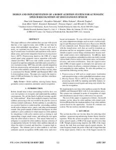
Fig. 1. Two-section Air-Octor manipulator in a bent configuration.
This work was supported in part by the Defense Advanced Research Projects Agency (DARPA) Defense Sciences Office through the Space and Naval Warfare Systems Center, San Diego, Contract Number N66001-03-C-8043.
0-7803-8912-3/05/$20.00 ©2005 IEEE.
3345
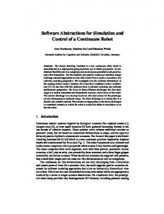
vature sections. The central chambers are manufactured by taking lengths of hose/ducting and pneumatically sealing the ends with end caps. The hose used for manufacturing features a loose metal spring (helix) that provides the chamber with structural support laterally and an ability to collapse upon itself longitudinally. This property of the central chamber allows for the controlled extension and retraction of the manipulator, a degree of freedom impossible for solid-backbone continuum robots. Unfortunately, the softness of the central chamber also makes it relatively fragile and prone to tears and leaks, and hence careful construction and exterior protection is important. The importance of the pneumatic integrity of the central chamber combined with its relative fragility motivates the addition of a protective hose within which the central chamber is housed. The outer protective hose also serves as a shell which provides the manipulator with a smooth continuous surface with which to perform whole-arm manipulation. Additionally, it provides a surface for the mounting of hardware such as cable guides or sensor payloads. The Air-Octor manipulator uses a combination of dc motors and pneumatic pressure regulators for actuation. DC motors, spools, and cables are combined to form a tendon-cable servo system which is used to control the bending of the manipulator sections. Three cables are used for each section, as illustrated by the configuration shown in Fig. 2. An electropneumatic servo pressure regulator is used to control and maintain the pressure in the chamber. In addition to the controllable extension/retraction discussed earlier, Air-Octor’s soft design provides controllable compliance modulation via pressure control of the central chambers. In total the manipulator section has three controllable degrees of freedom: two bending, one extension/retraction, and also controllable compliance modulation. For more details on the design of a single section of Air-Octor, see [9] and [11]. Additional degrees of freedom and capability were added to the single section Air-Octor by building a second section and mounting it on the end of the original manipulator, creating a two-section manipulator (as shown in Fig. 1). The motors and tendons for the second section are shifted 60 degrees from the motors and tendons for the first section. This allows for a compact single layer motor base. The second section’s tendon-cables are routed through cable guides mounted to first section’s outer hose. The pneumatic line for the second section is routed through the first section’s hollow central cham-
120°
Cable Guide for Second Section
Central Hose Cable Guide for First Section
P/R
Air Supply Legend
Tubing Pipefitting Plug Base Pressure Regulator
P/R
Fig. 3. Pneumatic routing diagram.
ber (see Fig. 3). Additionally, a separate pressure regulator is used to pressurize the second section. This two-section design gives the manipulator a total of six degrees of freedom (four bending, two extension/retraction, and also two controllable compliances). Overall, Air-Octor is 9 cm in diameter (with some variation to the soft design). Air-Octor’s individual sections can range in length from 13 cm to 45 cm. Factoring a 5 cm mounting gap between the two-sections, this translates into a twosection manipulator that can range in length from 31 cm (when fully retracted) to 95 cm (when fully extended). Curvature ranges are difficult to specify as the range varies with manipulator length, with tighter curvatures possible at shorter manipulator lengths. However, the range is sufficient enough to be able to whole-arm-grasp objects of varying size and shape (Fig. 7). The design of the robot gives it a number of unique characteristics. Unlike other cable-driven designs [22], [23] which employ two actuators per cable to vary the robot’s compliance, Air-Octor’s compliance is controlled pneumatically, so that it requires only one actuator per cable, reducing the size, expense, and failure rate of the remote actuation apparatus. In addition, its continuum nature as opposed to the rigid-link design of [22], [23] enables the robot to bend at any point in order to conform to a object to be gripped. However, because the pneumatic design relies on dryer hose, the range of each section’s stiffness is limited compared to [22], [23], in which electric motors provide a much wider stiffness range. Likewise, the payload capacity of the robot is relatively small
Outer Hose
Fig. 2. Cross-sectional schematic of the hose and tendon-cable configuration for a two-section Air-Octor.
P/R
3346
when bending the trunk to pick up an object, since the pneumatic pressure must be sufficient to maintain a bend trunk shape. In contrast, the trunk can lift significant weight vertically, without bending, limited only by the strength of the drive motors, because all weight in this case is supported by the tendons. The light weight of the robot enables it to bend and respond quickly to input, in comparison to designs which can bear large payloads, giving it a relatively high dynamic bandwidth for a soft, continuum manipulator. Finally, the large number of degrees of freedom – 6 bending and 2 in compliance, make it suitable for a wide range of tasks. The modular nature of the Air-Octor design allows for a number of sections to be similarly connected in series, provided that there is room for routing the pneumatics and tendon-cables. Assuming appropriate materials can be manufactured, this design is also scaleable from micro-scale to macroscale. Its potential applications include disaster relief, counterterrorism, medical devices, and remote explorations. Particularly, tentacle manipulators have great potential as local probes and victim retrieval/debris clearance devices.
From our earlier work [9], [11], [12], f 2 is
III. KINEMATIC ANALYSIS A. Computational Kinematics Kinematics for a continuum trunk can be derived as a series of transformations which relate trunk tip position x to cable lengths l through a series of intermediate steps as detailed in [10]. First, a Denavit-Hartenburg table relates x to θ and d , (coupled) joint variables in the table. Second, geometrical relationships provide a connection between θ , d and trunk parameters s, trunk length, κ , trunk curvature, and φ , the angle at which the trunk bends (as shown in Fig. 4). Finally, geometrical relationships between s, κ , and φ and cable length l complete the necessary kinematic transformations. This process can be summarized as D−H 1 2 x ←⎯⎯ ⎯ θ , d ←⎯ ⎯ s, κ , φ ←⎯ ⎯ l. f
f
(1)
Substituting f1 into the homogenous transformation matrix resulting from the D-H table yields
− cos φ sin κ s − sin φ sin κ s cos κ s 0
⎡ nd ( l1 + l2 + l3 ) −1 ⎛ g ⎞ ⎤ sin ⎜ ⎢ ⎥ ⎜ 3nd ⎟⎟ ⎥ g ⎢ ⎝ ⎠ ⎥ ⎡s⎤ ⎢ g ⎥ ⎢κ ⎥ = ⎢ 2 ⎥, ⎢ ⎥ ⎢ d ( l1 + l2 + l3 ) ⎥ ⎢⎣φ ⎥⎦ ⎢ ⎢ ⎥ ⎛ ⎞ + − 2 l l l 3 3 2 1 ⎢ tan −1 ⎜ ⎥ ⎟ ⎜ 3 l2 − l3 ⎟⎠ ⎥ ⎢ ⎝ ⎣ ⎦
(3)
where g = l12 + l2 2 + l32 − l1l2 − l2 l3 − l1l3, n is the number of cable guides on a trunk section, and d is the radius of the trunk. Substituting f 2 into A produces the final forward kinematics result. A similar process, in which the chain rule is used to combine Jacobians of each of the relationships, provides velocity kinematics. The process is ( )
( )
( ) 1 2 x ←⎯⎯⎯ ⎯ θ , d ←⎯⎯ ⎯ s, κ , φ ←⎯⎯ ⎯ l, J D−H
⎡ cos 2 φ ( cos κ s − 1) + 1 sin φ cos φ ( cos κ s − 1) ⎢ sin φ cos φ ( cos κ s − 1) cos 2 φ (1 − cos κ s ) + cos κ s A=⎢ ⎢ cos φ sin κ s sin φ sin κ s ⎢ 0 0 ⎢⎣ cos φ ( cos κ s − 1) ⎤ ⎥ κ ⎥ sin φ ( cos κ s − 1) ⎥ ⎥. κ ⎥ sin κ s ⎥ ⎥ κ ⎥ 1 ⎥⎦
Fig. 4. Manipulator variables φ , κ and s. The variable φ gives the rotation in the xy plane.
J f
J f
further detailed in [10]. Summarizing, J D − H J f1 is
(2) J D − H , f1
3347
⎡ sin φ ( cos κ s − 1) ⎢− κ ⎢ 0 ⎢ ⎢ cos φ ( cos κ s − 1) =⎢ ⎢ κ ⎢ cos sin κ s φ ⎢ ⎢ 1 − cos κ s ⎢ − sin φ sin κ s ⎣
(4)
−
cos φ (κ s sin κ s + cos κ s − 1)
κ κ s cos κ s − sin κ s κ2 sin φ (κ s sin κ s + cos κ s − 1) κ2 s sin φ 2
0 s cos φ
⎤ − cos φ sin κ s ⎥ ⎥ ⎥ cos κ s ⎥ ⎥ ⎥. sin φ sin κ s ⎥ ⎥ κ sin φ ⎥ ⎥ 0 ⎥ κ cos φ ⎥⎦
φ p, κ p, and s p then compute l p (1,1…3) from the rotated trunk parameters φ p + 60°, κ p, and s p . This algorithm, termed cable untangling, can be generalized to an n-section robot. This assumes the actuators are ra(5)
where h = cos κ s + κ s sin κ s − 1. Substituting (3) into (5) then multiplying the result by the Jacobian of (3) produces the final result, which has been omitted for brevity. B. Cable tangling/untangling However, these kinematics are insufficient for controlling a multi-section cable-actuated robot such as Air-Octor, due to the effect of the shape of proximal sections on the length of cables passing through these sections to distal sections. In general, the length ln ,i of the i th cable controlling the nth section can be found by summing the length l p ( j ,i ) required for the i th cable to pass through the j th proximal section over the n − 1 proximal sections then adding the length ld ( n ,i ) of the nth distal section being controlled by cable i , so that n-1
ln ,i = ∑ l p ( j ,i ) + ld ( n,i ).
120° , a n common design shared by [3]. Given “tangled” cable lengths l1…n,1…3, measured from each actuator to the cable’s termination, this algorithm computed the “untangled” length ld (1…n ,1…3) of cable which passes only through the distal-most portion of each section of the robot by descending the trunk once section at a time, subtracting off proximal length l p (1…n −1,1…3) from all distal cables passing through the current section.
dially arranged such the section-to-section offset is
(6)
j =1
Consider, for example, the two-section Air-Octor robot when the proximal section is straight, implying its curvature κ = 0. In this case, the cable lengths of the top section l1,1…3 measured from the actuators to their anchor points at the end of the top section are all equal to its arc length st , so that l1,1…3 = s p . Cable lengths of the bottom section, measured from the actuators to their anchoring points at the end of the bottom section, must pass through the top section, so that evaluating (6) for n = 2 yields l2,1…3 = l p (1,1…3) + ld ( 2,1…3). However, because the top section’s curvature is zero, any cable, such as the portion of the bottom section’s cables traveling to through the top section to the bottom section, must have the length s p . Therefore, the overall cable length for the bottom section cable can be easily solved as l2,1…3 = s p + ld ( 2,1…3). However, determining l p when κ ≠ 0 requires additional computation. As shown in Fig. 2, the three cables controlling the top section are offset by 60° from the three cables controlling the bottom section. Therefore, the length l p (1,1…3) of the portion of the bottom-section cables which pass through the top section is equal not to the length of the top-section cables l1,1…3 but instead to the length of the top-section cables when direction φ1 of the top section’s curvature κ1 is rotated by the section-to-section offset of 60° . This suggests an algorithm: first convert the top-section cable lengths to trunk parameters
Assign ld (1…n ,1…3) ← l1…n ,1…3. For j = 1 to n Compute φ , κ , and s from ld ( j ,1…3) using (3) because the j th section is now “untangled.” For k = j + 1 to n 120° ( k − 1) Compute l p ( k ,1…3) from φ + , κ , and s. n Subtract proximal length: ld ( k ,1…3) ← ld ( k ,1…3) − l p ( k ,1…3). End for End for The order in which these computations occur is important, because the formulas derived in the previous section used to convert between trunk parameters φ , κ , and s and cable lengths ld apply only to “untangled” or distal cable lengths. This prohibits the straightforward solution of (6) as n-1
ld ( n ,i ) = ln ,i − ∑ l p ( j ,i ) because l p ( j ,1…3) for the j th section must be j =1
computed from φ , κ , and s, which can only be found by first knowing the distal cable length ld ( j ,1…3) for that section. This distal cable length depends on proximal lengths from sections 1 to j − 1, which then depend on distal lengths from sections 1 to j − 1. To resolve this chain of dependencies, note that the first (most proximal) section has no proximal dependencies, allowing computation of φ , κ , and s then of l p ( 2…n ,1…3) . The algorithm can then walk down the trunk, “untangling” the current section by computing its distal cable lengths, transforming these to trunk parameters, then transforming them back to proximal cable lengths of trunk sections passing through the current section. Similarly, the following cable tangle algorithm computes “tangled” cable lengths l1…n,1…3 from “untangled” lengths ld (1…n ,1…3) by descending the trunk once section at a time, adding in proximal length l p (1…n −1,1…3) to all distal cables passing through the current section. Once again, this structure is mandated by the dependencies inherent in the defining equations.
3348
section is ( l2,1 , l2,2 , l2,3 ) = ( 91.0, 69.2, 63.5 ) . Untangled lengths for the top section are identical by definition, because the top section has no proximal sections through which its cables must pass. Computing untangled lengths for the bottom section gives ld ( 2,1) , ld ( 2,2) , ld ( 2,3) = ( 53.2, 41.3,30.6 ) . This results
Top section
(
)
in the robot configuration shown in Fig. 5, also illustrated by a 3-D model in the same figure. The 3-D models illustrates two results, one using the untangling algorithm derived here and the other without, instead simply subtracting top section cables lengths from bottom section cable lengths in order to obtain a non-untangled result of ld ( 2,1) , ld ( 2,2 ) , ld ( 2,3) =
Non-untangled bottom section
(
( 55.2,38.3, 22.6 ) for Untangled bottom section Fig. 5. Results of applying tangle/untangling to a two-section Air-Octor. Note the sagging due to gravity not present in the simulation.
Assign l1…n ,1…3 ← 0. For j = 1 to n Compute φ , κ , and s from l j ,1…3 using (3). Add distal length l j ,1…3 ← l j ,1…3 + ld ( j ,1…3). For k = j + 1 to n 120° ( k − 1) Compute l p ( k ,1…3) from φ + , κ , and s. n Add proximal length: lk ,1…3 ← lk ,1…3 + l p ( k ,1…3) . End for End for These algorithms complement and complete the kinematics derived earlier. Cable lengths sensed by the trunk‘s hardware, such as encoders on the motors of Air-Octor, are first untangled then fed to the kinematics. A control system specifies a desired trajectory, such as that produced by evaluating the velocity kinematics in (5) based on joystick input. These new desired positions are then tangled and fed to a control loop which servos the actual (measured) tangled lengths to the desired tangled lengths, moving the robot to the commanded location. Because the heart of these algorithms is a transformation from cable lengths to trunk parameters, they can be easily modified to accommodate various design choices by appropriately modifying the trunk parameters. For example, trunks such as [6] whose distance d from the trunk center to the location of the cable varies by section can be easily tangled or untangled by modifying the d used to convert between cable lengths and trunk parameters. Experimental results verify the correctness of these algorithms. Consider the two-section Air-Octor manipulator in which the distance from the trunk center to the cables is d = 4.5 cm, number of trunk segments per section n = 8, and the length of a non-bending intersection connection is 3 cm. Tangled cable lengths, measured in centimeters, for the top section is ( l1,1 , l1,2 , l1,3 ) = ( 35.8,30.9, 40.9 ) and for the bottom
)
comparison. Results obtained for trunk parameters for the top section is φ = 179° , κ = 0.0358 cm −1 , and s = 35.9 cm for both untangling methods. Therefore, as shown in the figure, the red top section for both methods is placed identically. The bottom section, drawn in blue, shows untangled section results of φ = −122° , κ = 0.0696 cm −1, and s = 41.9 cm while the non-untangled results for the bottom section, drawn in green, are φ = −121° , κ = 0.108 cm −1 , and s = 39.1 cm. As illustrated in the figure, the untangled trunk reproduces the curvature exhibited by the robot, while the non-untangled result does not. Therefore, changes made to the shape of the top section do not affect bottom section shape when using the untangling algorithm. In contrast, without an untangling algorithm, changes to the top section affect the shape of both sections. Note also that the untangled and actual trunks differ primarily in the curvature of the first section due to measurement errors and unmodeled effects such as the force of gravity, which causes the robot to droop due to the weight of the second section. Because the algorithms are not tied to the specific model given in (3), the same algorithms can be used with more accurate kinematics that compensate for gravity load for more accurate results. IV. IMPLEMENTATION A. Software Implementation Air-Octor control algorithms are currently implemented using the Rapid Prototyping (RP) system developed at Clemson by Jones [9]. Development is performed using the Simulink 5.0 software package to build a block diagram of the control system (using RP blocks). RP then converts the block diagram to C code and compiles the code to work with QMotor 3.0, which is run on the real-time QNX 6.2 operating system. QMotor is then able to use the compiled code to control the movement of the Air-Octor manipulator in real-time through control of the tendon-cable lengths. QMotor actuates the tendon-cable servo system through a Servo-to-Go board, which provides QMotor with 8 D/A outputs (6 for motors and 2 for pressure regulators) and 8 A/D inputs (6 for motor encoders and 2 for pressure sensors). QMotor allows the viewing of values and of graphs produced by the control program and allows users to modify control parameters (e.g. PID gains). In addition, the Jacobians identified in section III are symbolically computed then translated to C using Maple 9.5. Sub-expression elimination in the Maple code generator re-
3349
duces the processing time needed to compute the Jacobian, while CLapack library routines efficiently compute the necessary pseudo-inverse of the Jacobian. On a Pentium III 2.8 GHz processor, the entire control loop, including execution of the tangling/untangling algorithm and Jacobian computation, requires approximately 0.22 ms to execute, allowing for operation at 1000 Hz or greater. This system has been developed to remove much of the logistical overhead that is typically present in control algorithm development. As it is now, the system will allow control algorithms to be ported to manipulators of varying designs and degrees of freedom with reduced effort. In addition to the control modules, for practical implementation of the continuum manipulator the control system needs additional software modules. These additional modules include a safety module, a tangle/untangle module, and a user interface module. The safety module ensures that the control system does drive the manipulator into a configuration unsafe for the hardware. This module takes into account the limits on the length and the curvature the manipulator can achieve based on the material length of the manipulator available. This prevents the control system from attempting to drive the manipulator into configurations that are too long, too short, or too extreme in curvature (e.g. curvature that bends the manipulator around on itself). A tangle/untangle module adjusts the length of the tendon-cables of the second section as the first section moves, so that movement of the first section does not cause unwanted movement in the second section. This is necessary because the tendon-cables of the second section are routed along the length of the first section. The user interface module [21] allows the manipulator to be driven into positions via a joystick. Various joystick-to-manipulator mappings are implemented, the simplest one providing a one-to-one mapping of joystick location to manipulator direction of curvature and degree of curvature. Other mappings include velocity based controls. The buttons of the joystick allow for switching between control modes, manipulator sections being controlled, and modulation of the individual central chamber pressures. B. Hardware Implementation The kinematic models derived for Air-Octor assume that the hardware sections bend with constant curvature. This assumption holds, at least approximately, for virtually all continuum arm designs proposed to date [6]. Efforts have been made to ensure that the Air-Octor hardware conforms to this assumption. However, issues arising from the manipulator’s soft design and unrefined manufacturing methods compromise the assumption’s validity. The two most significant issues are kinking and sagging. Due to these issues, manipulator control sometimes lacks accuracy and precision. Nevertheless, the control system derived from the kinematics produces generally accurate movements. Sagging has been an issue with most continuum robot designs. However, the soft design of Air-Octor makes it an especially important issue for this manipulator. In Air-Octor, sagging occurs when the pneumatic pressure does not provide
the structural rigidity required to counteract the gravitational forces placed on the manipulator. For the current implementation, the pressure regulators operate within a range of 0 to 5 psi. The current manufactured central chamber is incapable of withstanding pressure much higher than this range. However, once the hardware is refined to be able to handle higher pressures, a greater pressure range is desirable. A greater pressure range provides a greater range of manipulator compliance and higher pressures provide greater structural rigidity, which reduce the effect of sagging. Greater structural rigidity also improves the manipulator’s payload capacity. The current version of Air-Octor has a relatively low payload capacity, and as such it is important that the manufacturing materials be as lightweight as possible. Kinking is another implementation concern that arises due to the soft design of Air-Octor. When the manipulator is not operating at “full” length (maximal s), the unused length of the central chamber tends to bulge out forming kinks as shown in Fig. 6, violating the circularity assumption made in kinematic development. This tendency is exaggerated at higher pressures. The presence of kinks can be minimized by lowering the central chamber pressure. However, lower pressures increase the effect of sagging and make the manipulator less responsive to change which can result in unwanted slack in the cables. Although there are some ongoing issues as discussed above, the two-section Air-Octor operates successfully as a low-cost, easily manufactured robotic test bed for continuum manipulator control algorithms and human-machine interfaces. We have used it to successfully verify our derived kinematic models and to perform some simple whole-arm grasping experiments (Fig. 7). V. DISCUSSION Air-Octor forms part of a larger effort in developing and deploying robust continuum robot arms [12]. In that effort, the kinematics and control environment described in this paper will be applied to four- and six- section continuum arms. AirOctor itself will continue to be further expanded and utilized as a test-bed for basic research in continuum robot development. In addition to investigating components and construction methods to improve the performance of the current manipulator, work is also being done to install additional proprioception (internal state) sensors as well as exteroception (environment state) sensors. Proprioception is important because cable lengths deduced from motor encoder counts are not always accurate in determining the state (shape) of the manipulator, especially when the manipulator is in physical contact with its environment. The proprioception sensors being investigated are goniometers, which detect bending angles, and CCD cameras, which can be used to perform visual servoing. Exteroception is important so that the manipulator can autonomously interact with its environment. The exteroception sensors being investigated include simple whisker touch sensors and cameras, which can run machine vision algorithms. When Air-
3350
Fig. 6. Kinking while picking up a box
Octor has these sensors it will be able to implement specialized control algorithms that perform obstacle avoidance, path planning, and whole arm manipulation. VI. CONCLUSION In this paper, we have described the design and real-time implementation of a modular soft continuum manipulator, AirOctor. The design is novel in combining both pneumatic and electric (tendon-driven) actuation within an internal/external hose structure. Experimental results verify the correctness of tangle/untangle algorithms which compensate for the effects of proximal trunk section shape on the overall cable length controlling distal sections. Additionally, a real-time kinematics and control architecture has been developed and implemented for Air-Octor, the results of which have been summarized in this paper. REFERENCES [1] [2] [3] [4] [5]
[6] [7]
T. Aoki, A. Ochiai, and S. Hirose, “Study on Slime Robot”, Proceedings IEEE International Conference on Robotics and Automation, New Orleans, 2004, pp. 2808-2813. M. Blessing and I.D. Walker, “Novel Continuum Robots with VariableLength Sections”, in Proceedings 3rd IFAC Symposium on Mechatronic Systems, Sydney, Australia, September 2004, pp. 55-60. R. Buckingham and A. Graham (2003). Reaching the unreachable – snake arm robots. Presented at International Symposium of Robotics. Available via: OCRobotics Ltd. www.ocrobotics.com. R. Cieslak and A. Morecki, “Elephant Trunk Type Elastic Manipultor – A Tool for Bulk and Liquid Type Materials Transportation”, Robotica, Vol. 17, pp. 11-16, 1999. I. A. Gravagne and I. D. Walker (2000). On the Kinematics of Remotely-Actuated Continuum Robots. In: Proceedings of the 2000 IEEE International Conference on Robotics & Automation, San Francisco, CA, USA. pp. 2544-2550. M. W. Hannan and I. D. Walker (2003). Kinematics and the Implementation of an Elephant’s Trunk Manipulator and Other Continuum Style Robots. Journal of Robotic Systems, 20(2), pp. 45-63. S. Hirose (1993). Biologically Inspired Robots. Oxford University Press. Fig. 7. Simple whole-arm manipulation experiments.
3351
[8] [9] [10]
[11]
[12] [13] [14] [15] [16] [17]
[18] [19]
[20]
[21] [22]
[23]
G. Immega and K. Antonelli (1995). The KSI Tentacle Manipulator. Proceedings 1995 IEEE Conference on Robotics and Automation, pp. 3149-3154. B. A. Jones (2004). Kinematics of a Novel Pneumatic Manipulator. Technical report, Dept. of ECE, Clemson University, February 2004. B. Jones and I. D. Walker, “A New Approach to Jacobian Formulation for a Class of Multi-Section Continuum Robots”, IEEE International Conference on Robotics and Automation, Barcelona, Spain, 2005, pp. 3279-3284. B. Jones, W. McMahan, and I.D. Walker, “Design and Analysis of a Novel Pneumatic Manipulator”, In Proceedings of 3rd IFAC Symposium on Mechatronic Systems, Sydney, Australia, September 2004, pp. 745-750. W. McMahan, B. Jones, I. Walker, V. Chitrakaran, A. Seshadri, and D. Dawson, “Robotic Manipulators Inspired by Cephalopod Limbs”, Proceedings CDEN Design Conference, Montreal, Canada, pp. 1-10, 2004. H. Ohno and S. Hirose (2001). Design of Slim Slime Robot and its Gait of Locomotion. Proceedings 2001 IEEE/RSJ International Conference on Intelligent Systems, Maui, Hawaii, USA. pp. 707-715. M. B Pritts and C.D. Rahn, “Design of an Artifical Muscle Continuum Robot”, Proceedings IEEE International Conference on Robotics and Automation, New Orleans, 2004, pp. 4742-4746. G. Robinson and J.B.C. Davies (1999). Continuum Robots – A State of the Art. Proceedings 1999 IEEE International Conference on Robotics and Automation, pp. 2849– 2854. N. Simaan, R. Taylor, and P. Flint, “A Dexterous System for Laryngeal Surgery”, Proceedings IEEE International Conference on Robotics and Automation, New Orleans, 2004, pp. 351-357. K. Suzumori, S. Iikura, H. Tanaka (1991). Development of Flexible Microactuator and its application to Robotic Mechanisms. Proceedings of the IEEE International Conference on Robotics and Automation, pp. 1622-1627. H. Takanobu, T. Tandai, and H. Miura, “Multi-DOF Flexible Robot Based on Tongue”, Proceedings IEEE International Conference on Robotics and Automation, New Orleans, pp. 2673-2678, 2004. H. Tsukagoshi, A. Kitagawa, and M. Segawa (2001). Active Hose: an Artificial Elephant's Nose with Maneuverability for Rescue Operation. Proceedings IEEE International Conference on Robotics and Automation, Seoul, Korea, pp. 2454-2459. J. F. Wilson, D. Li, Z. Chen, and R. T. George Jr. (1993). Flexible Robot Manipulators and Grippers: Relatives of Elephant Trunks and Squid Tentacles. In: Robots and Biological Systems: Toward a New Bionics?, pp. 474-479. M. Csencsits and B. A. Jones et. al. (2005) User Interfaces for Continuum Robot Arms. Accepted at the International Conferences on Intelligent Robotics and Systems, Edmonton, Canada, August 2005. S. Ma, M. Watanabe, and H. Kondo, Dynamic Control of Curveconstrained Hyper-Redundant Manipulators, Proc. 2001 IEEE International Symposium on Computational Intelligence in Robotics and Automation (CIRA'01), 2001, pp.83-88. S. Ma and S. Hirose, Development of a Hyper-redundant Multijoint Manipulator for Maintenance of Nuclear Reactors, Advanced Robotics, Vol.9, No.3, 1995, pp.281-300.
3352