Abstract---This work finds a rescue flying robot, which is used for detecting the
explosion environment of coalmine and rescuing miners who are trapped in the ...
ISSN: 2278 – 7798 International Journal of Science, Engineering and Technology Research (IJSETR) Volume 2, Issue 1, January 2013
Design and Implementation of PC Operated Flying Robot for Rescue Operation in Coalmines Aditya Kumar T , Pravin A, M S Madhan mohan, T V Janardhanarao Abstract---This work finds a rescue flying robot, which is used for detecting the explosion environment of coalmine and rescuing miners who are trapped in the underground coalmine after gas explosion. Rescue crews usually don't know the actual situation of the mine tunnel under such circumstances. Therefore it can be very dangerous for rescuers to go into mine tunnels to search survivors without detecting environmental information beforehand. This embedded control system can achieve many tasks of the robot, such as motion control, environmental information acquisition etc. At present, without monitoring the environmental conditions inside the coalmines the persons are sent into coalmines. Sensors are placed to their helmets, based on the sensed information the buzzer present on the helmet turns on. The disadvantage of this method is, it gives information regards people present inside coalmines only. Proposed system arise a solution for the existing method. It over comes all the drawbacks, mainly for rescue operation in coalmines.
And complicated as mine monitor systems maybe completely destroyed. The gas of CO, CH4, C02 and coal dust fill with the tunnels. The density of O2 may be unsuitable for human being. Furthermore, the temperature may be high and second explosion may occur. camera is installed at front place of the flying robot so the remote operator could have a full view of the robot's ambient environment.
Index Terms--- coalmine, embedded, flying robot, Zigbee
I. INTRODUCTION Coalmines detect and flying robot has been an indispensable auxiliary device in rescue work after mine accidents occur. There are many mine accidents occur in china every year, such as gas explosion, coalmines collapse, mine flood and so on. In 2009, 2631 miners were killed in some 1600 mine accidents in china as official figures showed. In traditional rescue work after mine accidents, rescuers are sent to the mine tunnels to search trapped workers directly. However, it is unsafe for rescuers because the situation underground is unknown
-----------------------------------------------------------------------------Aditya Kumar .T, PG scholar: Department of Electronics and Communication Engineering, BVC Engineering College, Odalarevu, India, Phone/ Mobile No. 8143881117. Pravin .A, Associative Professor: Department of Electronics and Communication Engineering, BVC Engineering College, Odalarevu , India , Phone/ Mobile No. 9492948869, M S Madhan Mohan , Associative Professor: Department of Electronics and Communication Engineering, BVC Engineering College, Odalarevu , India . T V Janardhanarao , Professor: Department of Electronics and Communication Engineering, BVC Engineering College, Odalarevu , India ,
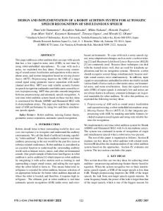
Figure 1. Coalmines rescue flying robot Three ultrasonic sensors are also used for environment perception sensors such as CH4, CO, 02 gas sensors, temperature sensor and PIR sensors are attached on the robot. Miniature Zigbee controlled helicopters are particularly suited for indoor navigation due to their lowspeed flight and in-place hovering capabilities. However, their small size places a frugal payload restriction on weight and power supply. Miniature cameras are an attractive option because they are small, passive sensors with low power requirements as show in Fig .1. Organization of this paper has 8 sections including introduction and Acknowledgment. part II describes related work and background part III describes helicopter platform part IV describes flying robot structure part V describes flying robot control system design part VI describes results and discussion part VII describes conclusion.
123 All Rights Reserved © 2012 IJSETR
ISSN: 2278 – 7798 International Journal of Science, Engineering and Technology Research (IJSETR) Volume 2, Issue 1, January 2013 II.
RELATED WORK AND BACKGROUND
There is a long and distinguished list of prior work on autonomous helicopters in outdoor environments. We refer the reader to a few papers ([1], [8], [9], [5]) because our problem of indoor flight addresses different issues. Several researchers have previously performed indoor flight experiments. However, these are usually conducted in uncluttered open spaces and using the more stable quad-rotor helicopter models. For example, Tournier et al. [25] used known patterns (Moire patterns) pasted in the environment to estimate the attitude and position of quad-rotor vehicles. He et al. [10] flew a quad-rotor in GPS denied indoor environments, using a Hokuyo laser (a device that gives 3D depth). Roberts et al. [20] used infra-red and ultrasonic sensors to fly a quad-rotor indoor in a large (7×6m) room,while [12] used vision to make a quad-rotor hover stably in an indoor environment. Quadrotors, however, have larger dimensions (e.g., 730mm in span for [3], 550mm for [20]) that make it harder for them to navigate in constrained spaces. Mejias et al. [14] used vision to land a helicopter while avoiding power lines. Nicoud and Zufferey [17] discussed the tradeoffs of designing indoor helicopters while D. Schafroth et al. [21] designed various test benches for micro helicopters and designed a dual-rotor single-axis helicopter with an omnidirectional camera. Mori et al. [16] used markers to stably hover a co-axial helicopter and go from one marker to another. In other related work, Michels et al. [15] used an onboard camera for autonomous obstacle avoidance in a small RC car driving at high speeds. They compute image features by convolving the image with a number of filters, and used linear regression to predict distances to obstacles. One can also build a map of the environment using Visual SLAM (e.g., [27], [6], [22]), in which the map is built using images captured from a camera. Ribnick et al. [19] estimate positions and velocities from monocular views. Such methods for estimating position/location from visual landmarks have been used in many robots which navigate on 2D ground. In comparison to ground vehicles, aerial vehicles have additional challenges posed by their 3D movement and the additional degrees of freedom in helicopter orientation. Furthermore, in the case of aerial navigation in highly constrained spaces, we require very fast response times; additional computation (e.g. feature computation) can prohibitively increase the latency of the controller. Our method of using images captured from a miniature camera could be applied to autonomous flights of other small aerial robots as well. For example, extremely small robots such as 25mm long micromechanical flying insects [7] can use miniature cameras.
III.
HELICOPTER PLATFORM
Our test platform is based on the E-flite Blade CX2 and Blade CX3 coaxial helicopters. These are cheap, readyto-fly micro helicopters. Each helicopter’s rotor diam-eter is 0.36m (with the landing gear in place) – this enables it to fly even in confined spaces. However, its total weight
is 227g and allows a payload with a maximum weight of only 70g. We chose the coaxial model because it provides stable flight and is considerably easier to control than its dual rotor counterparts. A Swan EagleEye wireless camera is mounted on-board (Fig. 1 inset) to stream images in real-time to the control algorithm. The camera is small (22 × 24 × 27 mm), light-weight (14g), and has low power consumption (100 mA). It relays back images of 640 x 480 resolution at 30 frames per second. This camera is our only perception source for the helicopter control – we do not even use inertial sensors in our algorithm. A wireless receiver attached to the laptop is used to receive the streaming frames. We use a commercial interface, Zigbee, to link the transmitter to the USB port of the laptop, via the trainer port (see Fig. 2). This enables the helicopter to be controlled via the PC using our control algorithm. We use the Spectrum DX6i 2.4 GHz transmitter, which is capable of translating PPM input to DSM signals that are broadcast to the helicopter. IV. FLYING
ROBOT STRUCTURE
The coalmines detect and rescue flying robot is composed of mechanical institution, control system, electronic system, communication system, sensor system and power system. The system structure of the robot is shown in Fig .2. Flying Robot is Two DC motors while two rear arms by another. Front arms are linked by a pole to move together, as well as rear arms.
Figure 2.System Structure of flying robot Robot can communicate with remote control system (RCS) through three ways. The first channel uses radio transceiver through RS232 interface; the second one is the optical fiber communication system which can transmit serial data signals by RS485 interface and cameras' video image at the same time as show in Fig .3. The last one uses wireless sensor net (WSN) to exchange information while a WSN node is attached to the robot through RS232 interface and robot's RCS connects to the WSN's server. When WSN is used, WSN's nodes should be deployed along the tunnel properly and communication distance can be extended greatly.
124 All Rights Reserved © 2012 IJSETR
ISSN: 2278 – 7798 International Journal of Science, Engineering and Technology Research (IJSETR) Volume 2, Issue 1, January 2013 Besides, video image signal can also be send by wireless image transmitter whose working frequency is 1.2GHz and communication distance is l Km in open field.
Figure 4. Control Structure of flying robot a. Figure 3. Schematic diagram Sensors system is composed of camera, gas sensor, temperature sensor and LDR Sensor. Some of these sensors output analog voltage signal sampled by peripheral A/D converter. With these sensors, remote operators can obtain the instantaneous information of the coalmines tunnel and robot can avoid collision when obstacles are laid on robot's path and adjust itself posture in time when it may fall down. The robot is powered by two lithium batteries which output 24V DC voltage. The main tracks driven DC motors and arms DC motors are all supplied by 24V DC converters. Other devices are powered by 12V or 5V DC converters.
PIC 18F4520 Micro controller
PICs generally have a few Kb of ROM, 256 or less bytes of RAM, 256 bytes of EEPROM and several analogue and digital IO lines. The program you write is stored in ROM, which comes in two types. One Time Programmable (OTP) chips can, as the name suggests, only be programmed once – there is no way to modify or erase the program once this is done. These are much cheaper than their counterparts with FLASH memory, and are used in production runs. Chips with FLASH memory are more expensive, but can be erased and reprogrammed many times and hence are useful for developing programs on.
V. FLYING ROBOT CONTROL SYSTEM DESIGN The control system which is regarded as the brain of the flying robot is the most important module of the robots. It gathers the robot's internal and external information, receives commands from the remote control system, and executes complex path planning algorithm and so on. The embedded control system structure of the coalmines detect and rescue flying robot as shown in Fig. 4. A. Control system Hardware design Fig.4 which shows the developed platform which uses single chip microcontroller PIC 18F4520,Light weight Camera ,LDR sensor ,GAS Sensor, Temperature sensor and communicates through Zigbee.
Figure 5. PIC 18F4520 Micro controller Considering that it is not unusual for a PC to have 1Gb of RAM, a few bytes may seem very restrictive, however it is adequate for most applications. Data stored in RAM is lost when the device is turned off, so EEPROM is available for non-volatile data storage. It is not used for all memory because it is much slower than RAM, and also has a limited life of about a million write cycles as show in Fig. 5.
Processor Architecture
The PIC computer follows the Harvard architecture. This means that instructions are held in different memory to data, unlike on a normal PC where instructions and data share the same memory. (This is Von Neumann
125 All Rights Reserved © 2012 IJSETR
ISSN: 2278 – 7798 International Journal of Science, Engineering and Technology Research (IJSETR) Volume 2, Issue 1, January 2013 architecture.) In the PIC, the instruction memory is 14 bits wide, and the data memory is 8 bits. This doesn’t really make any difference to you, the programmer, unless you want to write self modifying code, which is beyond the scope of this tutorial!
Programming Procedure
For a PIC to do anything useful, you have to write a program giving it instructions. A program may be written in either C or assembly language. In this tutorial, we’ll be using C because it’s much easier. The PIC18F4520 introduces design enhancements that make these microcontrollers a logical choice for much high performance, power sensitive applications. it consists of Three programmable external interrupts, Four input change interrupts,10-bit, 13-channel Analog-toDigital Converter module, Dual analog comparators with input multiplexing, High-current sink/source 25 mA/25 mA RS-232 (Recommended Standard 232) is a standard for serial binary data signals connecting between a DTE (Data Terminal Equipment) and a DCE (Data Circuitterminating Equipment). It is commonly used in computer serial ports. Here, we use MAX 232 (RS-232) for serial communication in between microcontroller and personal computer [12].
ZigBee coordinator(ZC): The most capable device, the coordinator forms the root of the network tree and might bridge to other networks. There is exactly one ZigBee coordinator in each network since it is the device that started the network originally. It is able to store information about the network, including acting as the Trust Centre & repository for security keys as show in Fig. 7. ZigBee Router (ZR): As well as running an application function a router can act as an intermediate router, passing data from other devices. ZigBee End Device (ZED): Contains just enough functionality to talk to the parent node (either the coordinator or a router); it cannot relay data from other devices. This relationship allows the node to be asleep a significant amount of the time thereby giving long battery life. A ZED requires the least amount of memory, and therefore can be less expensive to manufacture than a ZR or ZC.
b. Zigbee ZigBee is a low-cost, low-power, wireless mesh networking proprietary standard. The low cost allows the technology to be widely deployed in wireless control and monitoring applications, the low power-usage allows longer life with smaller batteries, and the mesh networking provides high reliability and larger range as show in Fig. 6.. The ZigBee Alliance, the standards body that defines ZigBee, also publishes application profiles that allow multiple OEM vendors to create interoperable products. The current list of application profiles either published or in the works are: Home Automation. ZigBee Smart Energy Commercial Building Automation Telecommunication Applications Personal, Home, and Hospital Care Toys
Figure 7. Connection of zigbee with Micro controller c.
Light dependent resistors are used to re-charge a light during different changes in the light, or they are made to turn a light on during certain changes in lights. One of the most common uses for light dependent resistors is in traffic lights. The light dependent resistor controls a built in heater inside the traffic light, and causes it to recharge over night so that the light never dies. Other common places to find light dependent resistors are in: infrared detectors, clocks and security alarms.
Figure 6. Zigbee protocol layers
LDR Sensor
Identification
A light dependent resistor is shaped like a quarter. They are small, and can be nearly any size. Other names for light dependent resistors are: photoconductors, photo resistor, or a CdS cell. There are black lines on one side of the light dependent resistor. The overall color of a light dependent resistor is gold. Usually other electrical components are attached to the light dependent resistor by metal tubes soldered to the sides of the light dependent resistor.
126 All Rights Reserved © 2012 IJSETR
ISSN: 2278 – 7798 International Journal of Science, Engineering and Technology Research (IJSETR) Volume 2, Issue 1, January 2013
e.
Function
The main purpose of a light dependent resistor is to change the brightness of a light in different weather conditions. This can easily be explained with the use of a watch. Some watches start to glow in the dark so that it is possible to see the time without having to press any buttons. It is the light dependent resistor that allows the watch to know when it has gotten dark, and change the emissions level of the light at that time. Traffic lights use this principle as well but their lights have to be brighter in the day time. d.
Temperature Sensor
The coolant temperature sensor is used to measure the temperature of the engine coolant of an internal combustion engine. The readings from this sensor are then fed back to the Engine control unit (ECU).data may also be used to provide readings for a coolant temperature gauge on the dash. The coolant temperature sensor works using resistance. As temperature subjected to the sensor increases the internal resistance changes. Depending on the type of sensor the resistance will either increase or decrease. There are two common types of coolant temperature sensors in use on automotive engines. Negative Temperature coefficient (NTC) and Positive temperature coefficient (PTC). The difference between the two is when the sensor is exposed to heat. In the case of Negative temperature coefficient sensor the internal Electrical resistance will decrease as it is exposed to more heat, whilst the opposite is true in a Positive temperature coefficient sensor. Most Automotive coolant temperature sensors are NTC sensors [28].
GAS Sensor
A CO gas sensor according to the present invention includes a gas collecting container for collecting a measured gas therein; a detecting section provided within the gas collecting container and having at least a pair of electrodes positioned through electrolyte; and a voltage applying apparatus for applying voltage to the detecting section. One of the electrodes of the detecting section is a detection electrode having the capability of adsorbing at least one of hydrogenous gas and CO gas when a voltage is applied and then oxidizing it. By introducing a measured gas into a gas collecting container of the CO gas sensor and carrying out electrolysis according to a potential sweep method or a pulse method with the measured gas being in contact with the detecting section, a CO gas concentration in the measured gas can be measured based on an electrical current value obtained at the detecting section and changes of the electrical current with elapse of time. According to the CO gas sensor of the present invention, it is possible to accurately carry out detection and measurement of the concentration of CO gas when CO gas is to be detected or measured even in a gaseous atmosphere containing a relatively large amount of hydrogen gas and CO2 gas. B. Control System Software Design The design of software is so vital for the whole system. The design was consisted of four parts included the Receiving instruction from PC, Operating the flying robot, collecting the data from sensors and transmit the data to PC through Zigbee as show in Fig .9.
Figure 8.Temperauer measuering using Circiut The ECU sends out a regulated reference voltage typically 5 volts to the Coolant Temperature Sensor, through the sensor where the voltage is decreased in relation to the internal resistance within the sensor which varies with temperature. This voltage is then returned to the ECU via the signal wire. The ECU is then able to calculate the temperature of the engine, and then with inputs from other engine sensors uses lookup tables to carry out adjustments to the engine actuators.
Figure 9. Overall flow chart of the software The μVision4 IDE is Windows-based software development platforms that combines a robust editor, project manager, and make facility. μVision4 integrates all tools including the C compiler, macro assembler, linker/locator, and HEX file generator. The evaluation version of Keil μVision4 IDE is used for this project.
127 All Rights Reserved © 2012 IJSETR
ISSN: 2278 – 7798 International Journal of Science, Engineering and Technology Research (IJSETR) Volume 2, Issue 1, January 2013 After the completion of developing the code Flash magic is used to dump the code into the microcontroller kit.as show in Fig. 10.
Figure 12. Flying Robot experiments in the indoor environment
Figure 10.Keil μvision4 configuration tool
VI. RESULTS AND DISCUSSION In order to verify the performance of the coalmines detect and flying robot based on the embedded control system, we have done many experiments to test its movement ability, obstacles avoidance ability, environment detecting ability, rescuing ability, system working reliability in various cases. In order to control and manage the electronic gadgets with the predefined modes, then sequence of instructions to be loaded into the microcontrollers. As shown in Fig. 11. flash magic tool will be used to configure the embedded hardware modules. The At89c51 microcontroller is supported by various commercially available IDEs for compiling and debugging of the code. Keil being one of them is the widely used IDE for PIC family of microcontrollers.
Figure 13. The controller setup showing the wireless image receiver, the laptop and the wireless transmitter. The Kiel IDE software will be used to build the hex file for these C programs. Overall hardware structure was designed, three modules with AT89C51 interfacing was design. By using RF Receiver, Zigbee transceiver and Zigbee Receiver controlling of data between proximity sensors, camera sensor flying robot and PC was done. The experimental results show that the flying robot can basically do the job of coalmines environment detecting and rescuing trapped miners under certain conditions and it will be used in rescue operations.
VII. CONCLUSION
Figure 11. Flash magic configuration tool Fig. 12. shows experiments that the robot communicated with the RCS via wireless sensor net and robot's obstacles avoiding ability in the indoor environment. Fig. 13. shows experiments of The controller setup showing the wireless image receiver, the laptop and the wireless transmitter
The coalmines detect and rescue flying robot is designed to help people execute tasks of detecting and rescuing after gas explosion in the underground coalmine. To address the special requirement, two dc motor tracks vehicle structure is adopted to enhance movement ability of the flying robot in the complex environment. Explosion proof, waterproof and dustproof design are also important features of the flying robot. The embedded control system based on the PIC Microcontroller AT89C51 designed for the flying robot has the features of stable, robust and reliable. Hardware design of the control system has the advantages of scalability, flexibility and low consumption. The PIC microcontroller has advantages of high processing speed, rich chip resources and supporting many different operating systems. Several peripheral devices are extended to enhance more than 10 system performance through interfaces of the
128 All Rights Reserved © 2012 IJSETR
ISSN: 2278 – 7798 International Journal of Science, Engineering and Technology Research (IJSETR) Volume 2, Issue 1, January 2013 development board. As the platform of software development, embedded has the advantages of scalable kernel, multi-user, multi-tasking and strong network function. Various fields experiments prove that the robot based on such embedded control system can basically meet the requirements of coalmines detecting and rescuing after mine disasters occur.
[20]
[21]
[22]
ACKNOWLEDGMENT
[23]
I acknowledge to college of BVC Engineering College, Odalrevu. I would like to thank my guide Mr. A. Pravin and my Head of Department Dr N.S. Murthy Sarma and principal Dr D.S.V. Prasad for their great help to my research.
[24]
[26]
REFERENCES [1]
[2]
[3]
[4]
[5]
[6]
[7]
[8] [9]
[10]
[11] [12]
[13]
[14]
[15]
[16]
[17] [18] [19]
[25]
P. Abbeel, A. Coates, M. Quigley, and A. Y. Ng. “An application of reinforcement learning to aerobatic helicopter flight”. In Neural Information Processing Systems (NIPS), 2006. A.Beygelzimer, S. Kakade, and J. Langford. “Cover trees for nearest neighbor.” In International Conference on Machine Learning (ICML),2006. S. Bouabdallah and R. Siegwart.” Backstepping and sliding-mode techniques applied to an indoor micro quadrotor.” In International Conference on Robotics and Automation (ICRA), 2005. J. Bouguet.” Pyramidal implementation of the lucas kanade feature tracker description of the algorithm. OpenCV,” Intel Corporation, 1999. A. Coates, P. Abbeel, and A. Y. Ng.” Learning for control from multiple demonstrations. “In International Conference on Machine Learning (ICML), 2008. M. Cummins and P. Newmann. Fab-map: “Probabilistic localization and mapping in the space of appearance.” International Journal of Robotics Research (IJRR), 27(6):647– 665, 2008. X. Deng, L. Schenato, W.-C. Wu, and S. Sastry.” Flapping flight for biomimetic robotic insects: Part ii- flight control design.” IEEE Trans on Robotics, 22(4):789–803, 2006. E. Feron and S. Bayraktar. “Aggressive landing maneuvers for unmanned aerial vehicles.” In AIAA Guid, Nav Cont Conf, 2006. V. Gavrilets, I. Martinos, B. Mettler, and E. Feron. “Control logic for automated aerobatic flight of miniature helicopter.” In AIAA Guid, Nav Cont Conf, 2002. R. He, S. Prentice, and N. Roy.” Planning in information space for a quadrotor helicopter in a gps-denied environments.” In International Conference on Robotics and Automation (ICRA), 2008. Hokuyu.” Range-finder type laser scanner urg-04lx specifications”. Online, 2005. N. Johnson.” Vision-Assisted Control of a Hovering Air Vehicle in an Indoor Setting”. PhD thesis, Bringham Young University,2008. E. Klingbeil, A. Saxena, and A. Y. Ng. “Learning to open new doors.” In Robotic Science and Systems (RSS) workshop on Robot manipulation,2008. L. Mejias, J. Roberts, K. Usher, P. Corke, and P. Campoy. “Two seconds to touchdown vision-based controlled forced landing.” In Int’l conf on Intelligent Robots and Systems (IROS), 2006. J. Michels, A. Saxena, and A. Y. Ng. “High speed obstacle avoidance using monocular vision and reinforcement learning.” In International Conference on Machine Learning (ICML), 2005. R. Mori, K. Hirata, and T. Kinoshita. “Vision-based guidance control of a small-scale unmanned helicopter.” In Int’l conf on Intelligent Robots and Systems (IROS), 2007. J.-D. Nicoud and J.-C. Zufferey. “Toward indoor flying robots.” In Int’l conf on Intelligent Robots and Systems (IROS), 2002. R. Panigrahy. “An improved algorithm finding nearest neighbor using kd-trees”. LNCS, (4957):387–398, 2008. E. Ribnick, S. Atev, and N. Papanikolopoulos. “Estimating 3d positions and velocities of projectiles from monocular views.”
[27]
[28] [29]
[30]
[31]
[32]
[33]
[34]
[35]
[36]
[37]
[38]
[39]
[40]
IEEE Transactions on Pattern Analysis and Machine Intelligence (TPAMI), 31(5):938–944, 2008. J. Roberts, T. Stirling, J.-C. Zufferey, and D. Floreano.” Quadrotor using minimal sensing for autonomous indoor flight. “In European Micro Air Vehicle Conference (AV), 2007. D. Schafroth, S. Bouabdallah, C. Bermes, and R. Siegwart.” From the test benches to the first prototype of the mufly micro helicopter.” J Intell Robot Syst, 54:245–260, 2009. B. Steder, G. Grisetti, C. Stachniss, and W. Burgard. “Visual slam for flying vehicles.” IEEE Transactions on Robotics, 24(5):1088–1093,2008. S. Thrun, W. Burgard, and D. Fox.” Probabilistic Robotics.” MIT Press, 2005. A. Torralba, R. Fergus, and W. T. Freeman. “80 million tiny images: a large dataset for non-parametric object and scene recognition.” IEEE Transactions on Pattern Analysis and Machine Intelligence, 30(11):1958–1970, 2008. G. Tournier, M. Valenti, and J. P. How. “Estimation and control of a quadrotor vehicle using monocular vision and moirre patterns.” In AIAA Guidance, Navigation, and Control Conf, 2006. M. Turk and A. Pentland. Eigenfaces for recognition. “Journal of Cognitive Neuriscience,” COM:132, 1990. B. Williams, M. Cummins, J. Neira, P. Newmann, I. Reid, and J. Tardos. “An image-to-map loop closing method for monocular slam.” In Int’l conf on Intelligent Robots and Systems (IROS), 2008. D. Marsh, "Network Protocols Compete for highway supremacy," in EDN Europe, vol.1, June 2003, 2003, pp. 26-38. Junyao Gao, Jianguo Zhu, Xueshan Gao, et aI, "Electric and control technique research of a coalmines detect robot," proceedings of the 9th International Conference on Electronic Measurement & Instruments (ICEMI2009). pp. 3-729 - 3-735, 1619 Aug, 2009 Gao Junyao, Gao Xueshan, Zhu Jianguo, et aI, "Coal mine detect and rescue robot technique research," proceedings of the 2009 IEEE International Conference on Information and Automation (ICIA2009). ppJ 06S-1 073, 22-24 June, 2009. Young, K.-K.D, Yong Quan Ou, Lun Huai Cai Ho, et aI, "Real time embedded control system development for wireless mobile platforms," proceedings of the 200S IEEE International Symposium on Industrial Electronics (ISlE 200S). pp.2022-2027, June 20-July 2, 200S Wei Wu, Geng HaiFeng, Guo Yan, "Embedded Control System Design for Autonomous Navigation Mobile Robot," proceedings of the 2009 Asia-Pacific Conference on Information Processing (APCIP 2009). pp.200-203, IS-19 July, 2009 Shouyin Lu, Liqiang Feng, Jiwen Dong, "Design of control system for substation equipment inspection robot based on embedded Linux," proceedings of the 200S Chinese Control and Decision Conference (200S CCDC). pp.1709-1712, 2-4 July, 200S Ward, C.C.lagnemma, K.ASML Lithography Syst, "A dynamicmodel- based wheel slip detector for mobile robots on outdoor terrain," Robotics, IEEE Transactions on Volume 24, Issue 4, Aug. 200S Page(s):S21 - S31 Zhang Yunzhou, Wu Dong, Xue Dingyu, et aI, "On the embedded control system for autonomous mobile robot", Journal of North eat ern University, 200S:Vo1.29, Nol [S] Sun Liang, Chang Qing, Ruan Xiaogang, "Design of embedded mobile robot controller", Computer Engineering and Applications, 2007:Vo1.43, No22 Liu Sen, Mu Chunli, Zhao Mingguo, "Humanoid robot controller based on ARM embedded sysytem", Journal of Tsinghua University, 200S:Vo1.4S, No4 G.Bruzzone, M.Caccia, G.Ravera, et aI, "Standard linux for embedded real-time robotics and manufacturing control systems", Robotics and Computer-Integrated Manufacturing, 25(2009), 17S190 Liu Sen, Mu Chunli, Zhao Mingguo, "Humanoid robot controller based on ARM embedded sysytem", Journal of Tsinghua University, 200S:Vo1.4S, No4 Yoichi Morales, Alexander Carballo, Eijiro Takeuchi, et aI, "Autonomous robot navigation in outdoor cluttered pedestrian walkways", Journal of Field Robotics, 2009:Vo1.26, NoS, 609-935
129 All Rights Reserved © 2012 IJSETR