This full text paper was peer reviewed at the direction of IEEE Communications Society subject matter experts for publication in the WCNC 2009 proceedings.
Design and Implementation of a Network-Centric Micro-Mobility Architecture Eduardo Zagari∗ , Rodrigo Prado∗ , Tom´as Badan‡ , Eleri Cardozo∗ , Maur´ıcio Magalh˜aes∗ , Jos´e Carrilho∗ Andr´e Berenguel∗ , Daniel Moraes∗ , Tiago Dolphine∗ , Thienne Johnson∗ , Lars Westberg§ ∗ School
of Electrical and Computer Engineering – State University of Campinas (Unicamp) 13083-970 – Campinas – SP – Brazil – Email:
[email protected] ‡ School of Electrical and Computer Engineering – Federal University of Goi´as – Goiˆania – GO – Brazil § Ericsson Research, Stockholm, Sweden
Abstract—This paper presents the design and implementation of the Mobility Plane Architecture (MPA). MPA is a network architecture that provides micro-mobility in a network-centric way, that is, the burden of supporting micro-mobility is placed on the network and not on the mobile nodes. The implementation employs RSVP-TE to establish IP/IP and MPLS pointto-multipoint tunnels in order to direct traffic to the mobile nodes. DHCP is used for tracking the mobile node locations and RSVP-TE opaque data carries the location information to install routes to them. Results obtained in a lab-sized network and some quantitative comparisons between MPA and other related work are presented as well. Index Terms—Wireless Internet, IP Mobility, Micro-Mobility
I. I NTRODUCTION The Internet Engineering Task Force (IETF) has published several standards addressing mobility in IP networks. In general, these standards can be divided into two categories, those supporting mobility across several networks (macro-mobility) and those supporting mobility within a single and potentially large network (micro-mobility). The Mobile IPv6 Protocol (MIPv6) [1] is at the center of the IETF standards. The basic functionality of MIPv6 is to hide from a correspondent node (CN) the changes in the mobile node’s (MN) actual IP routable (care-of) address (CoA). The element responsible for hiding the location of mobile nodes is the home agent (HA). MIPv6 has strong drawbacks when operating in environments with high handover rates (e.g., networks composed of small-sized cells). The reason is related to the need of updating, for every handover, the MN’s care-of address in the HA’s binding table. The high signaling overheads imposed by MIPv6 increases latency and packet loss during handover. Micro-mobility protocols aim to improve localized mobility by reducing the handover overheads. Various IP micromobility protocols (section III) have been proposed in order to support mobility within a domain. Unfortunately, the existing solutions for IP micro-mobility present strong drawbacks that make these solutions non deployable [2]. The main drawbacks are the need of: (i) IPv6 networks; (ii) complex protocols on the mobile node’s side; (iii) new protocols on the network’s core (e.g., mobility-aware routing protocols). The Mobility Plane Architecture (MPA) [2] [3] aims to eliminate these drawbacks by addressing micro-mobility in a
network centric way, that is, the burden of supporting micromobility is placed on the network. As such, MPA relies only on existing protocols already supported by the mobile device manufacturers. Moreover, MPA operates over IPv4 or IPv6 networks, and employs only well established network protocols at the network core. This paper is organized as follows. Section II presents the MPA architecture. Section III discusses the related works for supporting micro-mobility. Section IV shows the design and an implementation of MPA. Section V presents results regarding the performance of the architecture in a testbed network and also a performance evaluation study, comparing our results to other micro-mobility scheme. Finally, section VI concludes this paper. II. M OBILITY P LANE A RCHITECTURE The Mobility Plane Architecture (MPA) is an instance of a reference architecture for micro-mobility support in IP networks described in [3]. MPA itself is described in detail in [2]. The goal of MPA is to speed up the handover process in order to minimize communication disruptions when the mobile node change its network point of attachment. One of the requirements of this architecture is to place the burden demanded by micro-mobility on the network, not on the mobile nodes. Another requirement is to use, ideally, only well established network protocols. The key point of MPA is to employ an overlay network built above a transport network for directing traffic to the mobile nodes. This overlay network is composed of network elements called mobility aware router (MAR), which are routers enhanced with MPA functionalities. MPA employs point-to-multipoint (P2MP) tunnels in order to encapsulate traffic directed to the mobile nodes and allows a gradual deployment once the architecture elements are installed only at the MARs. MPA addresses the following issues related to mobility in IP networks: tunnel management (tunnel establishment, shutdown, and topology updating); secure mobile node attachment and handover; tracking of mobile node actual point of attachment (location); routing on the overlay network (decoupled from routing on the transport network); and quality and class of service (QoS/CoS) offered to the mobile nodes.
978-1-4244-2948-6/09/$25.00 ©2009 IEEE
This full text paper was peer reviewed at the direction of IEEE Communications Society subject matter experts for publication in the WCNC 2009 proceedings.
MPA specifies four functional blocks and the interactions among them [2]. The Tunnel Management functional block is responsible for the P2MP tunneling operations. The Mobility Routing functional block is responsible for tracking the MNs actual point of attachment and to route traffic to MNs’ correct location. The Address Configuration functional block is responsible for supplying L3 parameters to the MNs connecting or reconnecting to the access network. The Handover Helper functional block is responsible for facilitating the handover process, including L2 notifications (triggering), L2 re-association, secure node attachment, and handover related signaling. MPA, by conception, is weakly coupled with the underlay tunneling technology. Only the Tunnel Management functional block is aware of the tunneling technology being employed. Tunnels connect MARs together in such a way that MARs are the nodes and tunnels are the links of an overlay network. MPA employs P2MP tunnels, being each tunnel a directed acyclic graph (tree). As such, for a given P2MP tunnel, there is a single ingress (root) MAR, many branch MARs (traffic forking points), and many egress MARs (leaves). Ingress MARs receive packets targeted to mobile nodes and choose a P2MP tunnel segment to forward them. Branch MARs extract the packet from the tunnel, inspects it, and select a input tunnel segment to forward the packet. Egress MARs remove the packet from the output tunnel segment and submit it to regular IP routing. At the branch MARs, the binding between the input and output tunnel segments is done at layer 3 in case of IP/IP (IP over IP) tunnels and at the layer 2 12 for MPLS tunnels. In other words, with IP/IP tunnels the branch MAR inspects the destination address of the packet while with MPLS tunnels the branch MAR inspects the packet labels. III. R ELATED W ORKS MIP-based micro-mobility protocols, like HMIPv6 [4] (Hierarchical MIPv6) and FMIPv6 [5] (Fast-handover MIPv6), extend MIPv6 with new elements or messages in order to decrease handover latency. HMIPv6 introduces an element that acts as a home agent in the foreign network. This element prevents cross-domain MIPv6 signaling when the handover occurs inside a domain. FMIPv6 allows the mobile node to send and receive packets using the previous care-of address until it completes the process of registration of the new CoA. FMIPv6 aims to minimize packet loss during handover. However, both HMIPv6 and FMIPv6 require the MIPv6 implementation be updated on the mobile nodes in order to incorporate localized mobility and fast handover. A recent work under standardization is the Proxy MIPv6 (PMIPv6) [6]. PMIPv6 is a network-centric micro-mobility approach that, as our architecture, relies on tunnels inside a domain to direct traffic to mobile nodes. PMIPv6 defines two entities, the Mobile Access Gateway (MAG) and Local Mobility Anchor (LMA). A MAG is responsible to detect mobile node attachments, and, if security policies are fulfilled, establishes tunnels to the LMA for directing traffic to the
mobile nodes reached via this MAG. A MAG also emulates (via Router Advertisements messages) the mobile node’s home network in such a way that the mobile node may change the default router in a handover, but preserves the remaining L3 parameters. As the mobile node moves inside the domain, tunnels between MAG and LMA and routes on the LMA are updated. When the LMA receives a packet targeted to the mobile node it forwards the packet via the tunnel ending on the MAG to where the node is attached. Compared with MPA, PMIPv6 employs a single hierarchy of tunnels, and MPA employs a hierarchy of arbitrary levels, a feature important for traffic engineering. Signaling also differs between MPA and PMIPv6. MPA employs RSVP-TE, a very flexible signaling protocol that allows tunnel rerouting, QoS signaling, and constraint-based routing. PMIPv6 employs local binding update messages between MAG and LMA. Finally, although PMIPv6 considers IPv4 support as an extension, MPA does not need any extension for supporting both IPv6 and IPv4 as no IPv6 feature such as auto-configuration and extension headers are required by MPA. Other proposals rely on MPLS (Multiprotocol Label Switching) for supporting micro-mobility. References [7], [8], and [9] propose MPLS as a transport option to deliver packets to mobile nodes. These solutions present drawbacks related to the need of new protocols installed on the mobile nodes, packet processing at the core label switch routers (LSR) contrary to MPLS’ operation (e.g., the need to inspect the IP address of a packet), and rerouting of label switch paths (LSP) in response to every handover. The work described in [10] (MPLS/I-LIB) introduces the Intermediate Label Information Base (I-LIB), which is incorporated into MPLS forwarding, to reduce the end-to-end delays during handover. The MPLS/I-LIB proposes to modify the LIB in an intermediate LSR whenever a Registration Request from the MN to the Foreign Domain Agent (FDA) reach this LSR, which already has a forwarding entry for the MN in its LIB. This way, it is possible to establish a new LSP from the new Foreign Agent (FA) to the intermediate LSR, instead of the traditional method that is to establish the new LSP from the new FA to the FDA). The I-LIB requires the addition of new fields, for instance, the new and the old CoA, a Flag to perform an extra swap, MN address, and a Timer to decide whether or not the MN is active. However, it still depends on the periodical Router Advertisements messages to make the MN aware of the need to signalize the handover process, as shown in section V. IV. D ESIGN AND I MPLEMENTATION D ETAILS The design and the implementation of MPA demand networking protocols for its four functional blocks. The following subsections describe the design and implementation solutions for the Tunnel Management, Address Configuration, Mobility Routing, and Handover Helper functional blocks. A. Tunnel Management Functional Block RSVP-TE [11] (Resource Reservation Protocol - Traffic Engineering) was chosen for tunneling management and was
This full text paper was peer reviewed at the direction of IEEE Communications Society subject matter experts for publication in the WCNC 2009 proceedings.
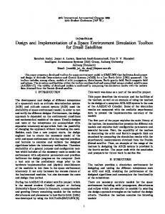
implemented with the recent P2MP extensions [12]. The architecture of the RSVP-TE implementation is shown in figure 1. The KernelProxy interface decouples the signaling functions from the forwarding functions and must be implemented by a router. This interface offers methods for installing and dropping P2MP tunnels. Such methods are called by the RSVP-TE daemon according to the dynamics of the signaling messages. This interface was implemented for both IP/IP and MPLS tunneling.
Management Interface RSVPD Core RSVP−TE Interface KernelProxy Interface
MPLS Tunnel ioctl system call
{OR}
NetFilter Module
Kernel Plane
Fig. 1.
MPLS Tunneling MPA-MPLS integration is done using label stacking of two levels. The outer label identifies a P2MP tunnel segment. P2MP tunnels are usually established via network management and considered static in the sense that their topology changes only in the long run. By the other hand, the inner label identifies the MN in the domain. This label defines inner tunnel segments within the P2MP (outer) tunnel segments. Inner tunnel segments are very dynamic, being managed by RSVP-TE. Figure 2 shows a simple scenario where A, B, C, D, and E are outer tunnel segments and X, Y, and Z are inner tunnel segments related directly to MNs. By combining inner and outer tunnel segments, a packet targeted to a MN can be delivered to any IP subnetwork connected by an egress MAR.
IP/IP Tunnel iproute2 utility
MPLS Module
segment side is removed. On core routers, both incoming and outgoing segments are removed. After the tunnel is removed the tunnel table is updated.
MPA−MPLS Overlay Network
Legend (inner tunnel)
IP Network
Outer tunnel (long lifetime)
Label X Label Y Label Z
A
Architecture of the RSVP-TE implementation. B
LSR−MPA aware
D
IP/IP Tunneling IP tunneling allows only point-to-point (P2P) connections. To be employed in MPA, which needs P2MP tunnels, several IP tunnels are concatenated in order to assemble a P2MP tunnel, with each IP tunnel acting as a branch of the P2MP tunnel. IP tunnels segments are installed between MARs and each tunnel segment can be created or removed separately. As such, it becomes possible to dynamically update the topology of a P2MP tunnel, an important feature for supporting traffic engineering strategies such as load balancing and traffic rerouting after link failure. IP tunneling is implemented by an object called IP Controller. This object implements the KernelProxy interface for Linux routers. IP Controller maintains a tunnel table storing the input and output tunnel segments of the P2MP tunnels established through the router. Each entry in this table stores information such as tunnel logical device name (e.g., tun0), the local and remote endpoints (IP addresses), the local physical interface name and the network address for the tunnel device. IP Controller employs the iproute2 utility for installing IP tunnel in the Linux kernel. iproute2 is a front-end to the ip utility that manipulates routing, devices, policy routing and tunnels in Linux kernels via the ioctl system call. Another operation performed by IP Controller is tunnel removal in response to RSVP-TE Tear messages or when a Path state on the router times out. From the router’s point of view, removing a tunnel means only to drop the endpoints of the tunnel. iproute2 is invoked in order to remove the tunnel from the Linux kernel. On egress or ingress routers, just one
C
IP Network
IP Network E
IP Network
Fig. 2.
Inner tunnel (short lifetime)
MPLS tunnel composition under MPA overlay network.
The operations of the MPLS tunneling scheme can be described as follows. Whenever a MN enters a MPA domain, at the ingress MAR, a FEC with a full-length address prefix of the mobile node is installed. Aggregation schemes can be employed in order to avoid FECs with full-length address prefixes. Under normal operation, when a packet arrives at the ingress MAR, this MAR performs a lookup for a matching entry in its FEC table. If such a matching is found, the two labels associated with the FEC are pushed into the MPLS packet. The packet is switched based on the outer label (P2MP tunnel trunk) until it reaches a branch MAR. At this point the label swapping is based on both labels as indicated by the MPLS label information base (LIB). When the packet reaches the egress MAR, the labels are stripped off and the packet is subjected to regular IP routing towards its destination. See [13] for more details on MPA-MPLS integration. The basic forwarding plane of MPLS architecture [14] and its P2MP tunnel extension [12] were implemented into the Linux kernel as a Linux module. This implementation is restricted to Ethernet networks with IPv4. A MPLS Controller component implements the KernelProxy interface. This com-
This full text paper was peer reviewed at the direction of IEEE Communications Society subject matter experts for publication in the WCNC 2009 proceedings.
ponent interacts with the MPLS kernel module via the ioctl system call (see Figure 1). Management Front-end A management front-end was developed in order to manage P2MP tunnels. The tool offers a menu bar with options for loading the physical network topology; discovering the logical topology of the network by polling the MARs for established tunnels; and managing (create, destroy, reroute, and monitor) P2MP tunnels. The front-end can be integrated with traffic engineering and/or QoS tools to support mobility in MPA, which is a current work. B. Address Configuration Functional Block The Address Configuration functional block requires a configuration protocol in charge for supplying L3 configuration parameters to the mobile nodes attached to the access network. The main parameters are IP addresses, network prefix, and default router. The main requirements for this protocol are security and the controlled assignment of L3 addresses (e.g., a mobile node receives the same L3 address while it roams inside a domain). The Address Configuration functional block relies on DHCPv4/v6 (Dynamic Host Configuration Protocol for IPv4/v6) due to its ability to fulfill these requirements. In addition, DHCPv4/v6: • can be easily integrated with authentication standards such as RADIUS (Remote Authentication Dial In User Service); • allows a controlled attachment of mobile nodes, e.g., the number of mobile nodes and address ranges per link can be limited; • allows the mobile node to inform the server about its preferences using the User Class option in the Solicit or Request messages. DHCPv6 does not supply default router along with the IPv6 address, a responsibility of the Neighbor Discovery (ND) for IPv6 protocol. On IPv6 networks, MPA employs Radvd (Linux IPv6 Router Advertisement Daemon) on access routers in order to send periodical ND Router Advertisement (RA) messages through the aerial links. These messages have the bit M set in order to instruct the mobile nodes not to perform address auto-configuration. As another prevention against auto-configuration, Radvd issues only information about the default router and no information about the prefix of the network. On Linux IPv6 implementation, it is possible also to disable address auto-configuration via manual configuration. As the period of RA messages are long (seconds), address configuration in IPv6 is critical for handover. In order to speed up L3 configuration in IPv6 networks, a mobile node can issue a Router Solicitation as soon as it attaches to a new link. Another alternative is to synchronize address configuration with mobile routing as shown in the next subsection. On IPv4 networks there is no need for router advertisement daemons since DHCPv4 Reply messages contain the network prefix and default router as needed by the mobile node.
Security mechanisms available for DHCP can be used in MPA implementations. For instance, IPSec tunnels can be established between the client and the server for secure communication during the host configuration process in IPv4. Of course, these mechanisms demand extra configuration on the mobile nodes. C. Mobility Routing Functional Block In MPA the Mobility Routing functional block is responsible for redirecting traffic to the correct point of attachment of a mobile node. Mobility routing includes at least three activities: 1) location of mobile nodes; 2) mobility signaling: to propagate location information to a subset of routers; 3) route updating: to update the route to the mobile node in response to the mobility signaling. The Mobility Routing functional block detects the location of a mobile node as soon as it performs a handover. The location is based on the interception of DHCP messages issued by the mobile node as soon as it connects to a new link (i.e., performs a handover). The iptables utility, a packet filter available for Linux, was employed for this task. DHCP Offer messages targeted to the relay agent port 547 is trapped on the access router and sent to the user space. At the user space, a code extracts from the message the mobile node identifier (its MAC address) and the address assigned by the DHCP server to the mobile node and notifies the local RSVP-TE daemon. Upon receiving notification, the daemon starts the mobility routing process. In IPv6 networks, the Mobility Routing functional block also issues a series of Router Solicitation message in behalf of the mobile node performing stateful address configuration in order to force the router to issue a timely RA message. Mobility signaling employs the same RSVP-TE protocol. Once notified about a handover, the RSVP-TE daemon generates a Resv message carrying an opaque object with the identification of the moving mobile node (MAC and IP addresses) [2]. The message travels the P2MP tunnel bottom-up, being processed by the MARs up to the ingress MAR. During the processing of this message, the RSVP-TE daemon calls a KernelProxy method in order to redirect the traffic to the new MN’s location. This location is reached through the tunnel segment from where the Resv message was received. With IP tunneling, the Controller performs route updating simply by dropping the actual route to the MN (e.g., via tunnel segment tun0) and installs a new route via the segment where the Resv message was received (e.g., via tun2). iproute2 is employed for these operations. Routing with IP tunneling has two advantages. Firstly, IP tunneling keeps mobility routing information stored on the router’s IP routing table. Secondly, IP tunneling works both for IPv4 and IPv6. In MPLS tunneling, route updating is performed at the branch points by inspecting the outer and inner labels. The outer label is extracted from the RSVP-TE Resv message. The inner label is computed with a hashing function applied to the IP address of the MN present in the opaque object in the Resv
This full text paper was peer reviewed at the direction of IEEE Communications Society subject matter experts for publication in the WCNC 2009 proceedings.
message. At a branch MAR, a rebind of the inner label to a new outer label occurs. Figure 3 shows the updating of a LIB in a branch MAR caused by a handover of a MN mapped into the inner label Y formerly being reached via the outer tunnel segment B and now being reached via the outer segment C. XY
Mobile node location (inner header) A
Tunnel segment (outer header) in eth0 A X B eth0 A Y B eth0 A Y C
eth0
Branch MAR
LIB
eth1
eth2
B
C Mobile node movements update LIB
Fig. 3.
out X eth1 Y eth1 Y eth2
L2 C Y IP packet labels
Downstream MAR
LIB updating during a mobile node handover.
D. Handover Helper Functional Block The Handover Helper functional block is responsible for predictive and seamless handover. MPA implements a seamless handover function based on traffic bicasting. On IP tunneling, bicasting is implemented by installing a temporary iptables filter (Tee filter) that replicates packets on two tunnel devices. On MPLS tunneling, bicasting is implemented by keeping temporarily both old and new LIB entries with the same inner label. Bicasting needs the mobile node to inform the current access router about its intention to perform handover to a new location. If the MN is not able to do it, an entity in the network may forecast the MN movement. V. T ESTS AND R ESULTS The tests were conducted on a 8-node network. Each node consists of a Linux router fitted with 4 interfaces. A node acts as a ingress MAR, three nodes act as branch MAR, and 4 nodes act as egress MAR. Each egress MAR has a IEEE 802.11g access point connected to one of its interfaces as shown in Figure 4. Physical link P2MP tunnel
R1
R2
R4
R3
R5
R6
R7
R8
AP1
AP2
AP3
AP4
MN
Fig. 4.
MPA Testbed
Table I shows the times obtained when making handover from Access Point 1 to Access Point 4 (Figure 4). The experiment used two CBR UDP traffic with packets of 340 bytes size to simulate a multimedia traffic with packets transmitted at fixed rates of 10 ms and 20 ms for both IP/IP and MPLS tunneling schemes. For these experiments were employed Linux boxes running kernel 2.6.24.3 as routers and a notebook with the Intel PRO/Wireless 2200BG network adapter running Windows XP SP3 as the MN. The access points employed were Mikrotik RouterBoard 133 running HostAPd over OpenWrt firmware and configured with WPAPSK + TKIP authentication scheme. Interval Time (ms) 10 20 10 20
Tunneling IP/IP IP/IP MPLS MPLS
Packets Lost 124 62 124 62
Delay (ms) 1240 1240 1240 1240
TABLE I T OTAL (L2, L3, AND MPA) OVERHEADS FOR DOWNLOAD TRAFFIC .
The goal of the tests was to measure the handover overheads. The handover overhead is composed of L2, L3 and MPA overheads. L2 overhead is the time necessary to perform L2 association. It varies from 40 to 1500 ms and depends on the network card and device drivers installed on the MN, direction of traffic (uplink/downlink), and access point brand. L3 overhead is the time necessary to configure (via DHCP) the L3 parameters: network prefix, IP address, and default router. This overhead varies in our network between 15 and 25 ms. The MPA overhead measured was around 110 ms to update a route (IP/IP tunneling) or a inner tunnel (MPLS tunneling) on a branch MAR. This overhead includes the RSVP-TE message processing and route update or inner tunnel redirection performed by the Controller (IP or MPLS) and does not depend on the L2 and L3 overheads. To evaluate the overhead imposed by the tunnel topology in MPA, a queueing network model (QNM) for the node attachment was developed and simulated in a QNM Simulator (JSIMgraph). Two distinct scenarios using two different hardwares were simulated for performance evaluation. Figure 5 illustrates the time to MPA handle a MN attachment (MPA response time) when using two and three hierarchy levels of MARs for both the best and the worst case (network cards and drivers), varying the node arrival rate from 0.01 to 2 nodes/second. It was also performed a quantitative comparison between MPA and the MMPLS/I-LIB approach described in [10]. The metrics analyzed in the simulation experiment were the system throughput (number of user’s requests completed per second) and the system response time for node attachments. It was considered two and three levels of hierarchy for MPA and three different mean values before Router Advertisements for MMPLS/I-LIB (0.05, 0.5 e 1 second). Figures 6 and 7 show the simulation results. The reason for both behaviors, the throughput saturation and the exponential growth of the response time of the MMPLS/I-LIB approach, can be ex-
This full text paper was peer reviewed at the direction of IEEE Communications Society subject matter experts for publication in the WCNC 2009 proceedings.
Node Attachment Response Time 4.5 4
3.5
seconds
3 2 levels − best scenario 2 levels − worst scenario
2.5
3 levels − best scenario 3 levels − worst scenario
2
1.5
1
0.5
0
0.2
0.4
0.6
Fig. 5.
0.8
1 1.2 Arrival Rate
1.4
1.6
1.8
2
MPA Response Time
plained by its strong dependency with the mean time between consecutive Router Advertisements, which is at least 1.5 second as stated in RFC 4861 [15]. Comparison − System Throughput 2
MPA−2 levels MPA−3 levels
1.8
ADV=0.05 ADV=0.5
1.6
ADV=1 Resquests/sec
1.4 1.2
R EFERENCES
1 0.8 0.6 0.4 0.2 0
0
0.2
Fig. 6.
0.4
0.6
0.8
1 1.2 Arrival Rate
1.4
1.6
1.8
2
Mean system throughput comparison Comparison − System Response Time
4 MPA−2 levels MPA−3 levels ADV=0.05 ADV=0.5 ADV=1
3.5
3
Seconds
2.5
2 1.5
1
0.5
0
VI. C ONCLUSIONS In this paper we presented an implementation to the Mobility Plane Architecture, described in detail in [2]. The following conclusions can be drawn from this work: 1) Architectures supporting micro-mobility at the IP level are feasible for IPv4 and IPv6 networks employing well accepted standards with only few extensions already foreseen by the standards (such as opaque objects in RSVP-TE messages). 2) It is feasible to offer mobility services to nodes fitted solely with the network protocols supplied by the manufacturers such as DHCP and WPA. 3) Initial evaluation of MPA demonstrated that it is a feasible approach for supporting mobility services with handover overhead in the range of tens of milliseconds. 4) MPA offers several opportunities for traffic engineering, for instance, traffic differentiation inside P2MP tunnels, tunnel rerouting for resource optimizations, and predictive and seamless handover. Presently, we are working on enhancing MPA in the subjects of traffic engineering, scalability assessment via simulation models, and policy-based management and configuration. ACKNOWLEDGMENT This work is supported by Ericsson Brazil.
0
0.2
Fig. 7.
0.4
0.6
0.8
1 1.2 Arrival Rate
1.4
1.6
1.8
2
Mean system response time comparison
The MPA overhead of around 100 ms is adequate for a prototyping network serving applications such as video on demand and Web browsing. We believe that an optimized implementation of MPA can reduce this overhead to 50 ms, a value suitable for real-time voice applications.
[1] D. Johnson, C. Perkins and J. Arkko, “Mobility Support in IPv6,” IETF, RFC 3775, June 2004. [2] E. Zagari et al., “MPA: a Network-Centric Architecture for MicroMobility Support in IP and MPLS Networks,” Sixth Annual Conference on Communication Networks and Services Research (CNSR2008), May 2008. [3] R. Prado et al., “A Reference Architecture for Micro-Mobility Support in IP Networks,” The Thirteenth IEEE Symposium on Computers and Communications (ISCC2008), July 2008. [4] H. Soliman et al., “Hierarchical Mobile IPv6 Mobility Management (HMIPv6),” IETF, RFC 4140, August 2005. [5] R. Koodli, “Fast Handovers for Mobile IPv6,” IETF, RFC 4068, July 2005. [6] S. Gundavelli, K. Leung, V. Devarapalli, K. Chowdhury and B. Patil, “Proxy Mobile IPv6,” IETF, RFC 5213, August 2008. [7] D. K. F.A. Chiussi and S. Krishnan, “A Network Architecture for MPLSbased Micro-Mobility,” IEEE WCNC 2002, vol. 2, pp. 549–555 vol.2, Mar 2002. [8] Rami Langar, Samir Tohme and Gwendal Le Grand, “Micro Mobile MPLS: A New Scheme for Micro-mobility Management in 3G All-IP Networks,” ISCC, vol. 00, pp. 301–306, 2005. [9] V. W. Kaiduan Xie and V. Leung, “Support of Micro-Mobility in MPLSbased Wireless Access Networks,” IEEE WCNC 2003, vol. 2, pp. 1242– 1247 vol.2, 16-20 March 2003. [10] S. Fowler and S. Zeadally, “Fast Handover over Micro-MPLS-Based Wireless Networks,” Computers and Communications, 2006. ISCC ’06. Proceedings. 11th IEEE Symposium on, pp. 181–186, 26-29 June 2006. [11] D. Awduche et al., “RSVP-TE: Extensions to RSVP for LSP Tunnels,” IETF, RFC 3209, December 2001. [12] S. Yasukawa, “Signaling Requirements for Point-to-Multipoint TrafficEngineered MPLS Label Switched Paths (LSPs),” IETF, RFC 4461, April 2006. [13] T. Badan et al., “A Network Architecture for Providing Micro-Mobility in MPLS/GMPLS Networks,” IEEE Wireless Communications & Networking Conference (WCNC2009), May 2009. [14] A. V. E. Rosen and R. Callon, “Multiprotocol Label Switching Architecture,” IETF, RFC 3031, January 2001. [15] T. Narten, E. Nordmark, W. Simpson and H. Soliman, “Neighbor Discovery for IP version 6 (IPv6),” IETF, RFC 4861, September 2007.