Design and Implementation of a Remote Laboratory Platform Using MATLAB Builder for NE ILHAMI COLAK,1 ERDAL IRMAK,1 ERSAN KABALCI,2 FATIH ISSI1 1
Faculty of Technology, Department of Electrical and Electronics Engineering, Gazi University, Ankara, Turkey
2
Faculty of Engineering and Architecture, Electrical and Electronics Engineering, Nevsehir University, Nevsehir, Turkey
Received 18 April 2011; accepted 13 November 2011 ABSTRACT: In this study, a highly instructive and novel remote laboratory platform using up to date software and hardware units is designed to teach main concepts of Electrical Engineering with the help of webbased simulations and remote accessible experiments in real time. Interactive experimental applications for direct current (DC) motors and several electrical circuits are carried out in this study to test the efficiency of the system. First, mathematical model of each simulation is developed in MATLAB and then all models are transferred into .NET platform by means of MATLAB Builder for NE toolbox. A dynamic library for each model is also created using NE toolbox. Then, all libraries are embedded into an interactive web page designed in ASP.NET platform. Data transmission between the server and the real experimental set is established by a microprocessor via the USB port to achieve the experimental studies over the Internet in real time. While remote experiments are being performed, data obtained by the experimental set are simultaneously transferred to the MATLAB. Then, the system generates both graphical and numerical results about the current experiment and all results are sent to a user-friendly web interface to give users some feedback on the experiment. ß 2011 Wiley Periodicals, Inc. Comput Appl Eng Educ; View this article online at wileyonlinelibrary.com/journal/cae; DOI 10.1002/cae.21553 Keywords: MATLAB builder for NE; virtual laboratory; real time analysis; electrical machines
INTRODUCTION Teaching only theoretical concepts without using any visual supporting material is one of the most important deficiencies in vocational education, which makes it difficult to understand the theoretical parts of education. Although performing the experimental studies in real laboratory environments is the best solution for this problem, there are several factors to build an experimental setup such as high cost of experimental boards and inadequacy of time. On the other hand, information technology and simulation software may assist lecturers to manage experimental studies efficiently. In addition, laboratory costs may be reduced and time may be saved by the way of using computer-aided experiments. Furthermore, computer-based analysis provides a real time, faster and more accurate results than classical ones. The most important part of computer-aided analysis is to build an optimum infrastructure, which usually
Correspondence to E. Irmak (
[email protected],
[email protected]). ß 2011 Wiley Periodicals, Inc.
needs to be coded by a programmer to obtain a system that is very close to the original application. In this study, a didactic virtual laboratory application is achieved using actual programming techniques and hardware interfaces. One of the most effective features of the system is its interactive structure that can be accessed over the Internet. Therefore, saving the time and reducing the costs are achieved in addition to eliminating the physical laboratory requirements. Furthermore, users, who have theoretical knowledge but want to observe the system responses experimentally in several operating conditions, may easily find some answers to the questions in their minds by a fast and accurate way. Recently, several experimental boards with interactive web applications are presented in the literature. The studies are related to subjects such as the design of a remote accessible e-lab [1], implementation of a virtual laboratory to speed control of asynchronous motor with PI controller [2], four-quadrant control of a DC motor with virtual laboratory [3], engineering design, analysis, and simulation with MATLAB over Internet [4], remote control laboratory with MATLAB and Simulink [5], web-based laboratory for DC motor experiments [6], interactive education applications with MATLAB web server [7], development of an educational Internet interface with MATLAB Builder
1
2
COLAK ET AL.
for NE for digital modulation techniques [8], synchronous machine application for virtual electrical machines laboratory [9], USB-PC data transfer interface with PIC18F4550 microcontroller [10], synchronous generator experiment with virtual electrical machines laboratory [11], digital electronic laboratory design for digital input–output application with PIC16C765 microcontroller [12], Internet-based energy and power quality observation system [13], Internet-based real time line tracking robot application [14], Internet-based industrial heating measurement and control system [15], virtual electrical machines laboratory to detect saturation state application of asynchronous motor [16], design, application, and evolution of Internet-based power electronics laboratory [17], Internet-based remote control laboratory [18], several Internet-based interactive education infrastructures [19–26], web-based virtual laboratories for reinforced concrete education [27] and automatic control teaching with virtual laboratory [28]. All the studies cited above minimized the cost while eliminating risk factors which may occur during conventional laboratory environments due to high voltage applications. There are several differences between the system presented in this study and the others mentioned above. Some studies in the literature are only based on MATLAB Web Server (MWS) that is not an actual tool [1–7]. On the other hand, merely simulation exercises are given in the studies [8,20]; whereas, .NET platform, one of the most up to date software architecture in these days, is used in this article. Thus, the enhanced features of .NET enable the whole system to integrate easily with several studies. Furthermore, flexibility and usage of the system with graphical representations are increased in this study since the Matlab Web Figure tool is used, which is not supported by the MWS. Another novelty of this study is to utilize universal serial bus (USB) 2.0 instead of serial or parallel ports, which are widely used in some studies [13–15]. Thus, the connection speed and the data transmission rate of the system developed are increased to a maximum level (480 Mbit/s). A special data acquisition system is developed in the system to decrease the cost, whereas, most similar systems in the literature use highly expensive and ready to use data acquisition cards [3,5,16–19]. The data acquisition system designed performs a simple data communication between the USB port of the server and the motor drive circuit. The system presented includes a fully integrated learning system for electrical engineering education in which students can use the several simulations of basic electrical circuits, comparative simulations for several controller types, and real rime experimental studies. While the basic electrical circuits are analyzed with only simulations, speed experiments for a DC motor are supported by real time applications. Both for the simulations and the real time experiments, parameters of the whole system can be adjusted by trainer on a user-friendly web interface. Data obtained from the experimental set in real time can be stored in the local disk or can be transferred into the MATLAB to generate some graphs related to the experiment. This way of data process allows trainers to observe circuit responses under several operations. The developed system is intended to minimize the physical laboratory requirement in electrical machines subjects in electrical engineering curriculum. Although the experiments analyzed in this article cover only DC machine experiments, the developed tool allows to control other electric motors over user interface. Several driver boards and motor types can be connected to the system easily.
IMPLEMENTATION OF THE SYSTEM The system is constituted involving two fundamental infrastructures that are software and hardware. The software infrastructure includes the Internet page that supports the user interactivity, the dynamic libraries those contain MATLAB mathematical models, WebFigure component, and USB communication software. The hardware infrastructure is constituted with a microcontroller card with L298 IC that supports USB communication and motor drive control, and a tachogenerator that is coupled to a direct current motor and an IP camera.
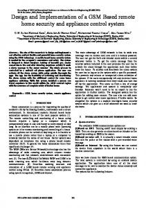
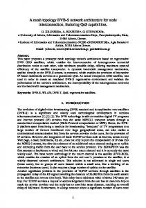
Software Substructure It is highly important to adapt previously coded software sets to various platforms due to rapid development of software architectures. In this study, saving time and reducing costs have been possible since the software model of the system designed enables to code conversation among different platforms. In addition, MATLAB supports to transfer the prepared model to various platforms such as COM objects, .NET platform, Java platform, Excel snippets, and Windows applications as shown in Figure 1 [29,30]. The mathematical models to be used in the design are prepared using MATLAB and compiled for .NET platform with MATLAB compiler. As shown in Figure 2, the compilation process is done using deploytool command and performed in a new project environment. A new class is defined in the project and required model files are added to this class. The dynamic libraries to be used in Asp.Net web page are obtained using Build command after compilation process. Web Page Design. A server page is constituted to realize user interaction with system. The interaction between the user and the system is supplied by Matlab Builder for NE toolbox and Asp.NET, which uses .NET framework 4.0. Asp.NET framework integrates the dynamic model libraries with the Internet pages designed to provide a data communication between the user interface and the experimental setup. A sample flowchart for the real time analysis is given in Figure 3. The web page design is performed C# programming software of Microsoft Visual Studio software development kit (SDK). The web page, prepared with object oriented programming support of SDK, is capable of being developed and updated. The dynamic libraries that are obtained during design steps are adapted to the web page. The control objects that may be required by user are also added to the web page with MATLAB WebFigure to increase interactivity. MATLAB WebFigure Control Component. The development of MATLAB Compiler has provided to integrate the various programming platforms with MATLAB. This integration also allows exporting obtained data in different file formats. The WebFigure object provides to export visual objects instead of exporting just data. The model results obtained can be inserted to other platforms as visual objects owing to properties of WebFigure. Furthermore, this object provides an easy way for usage of its properties. These properties can be defined as free graphical movement, 3D movement, zoom in, and zoom out. Figure 4 illustrates a sample step of web page design by embedding WebFigure and WebControl objects.
REMOTE LABORATORY PLATFORM
3
Figure 1 MATLAB compiler capabilities. [Color figure can be viewed in the online issue, which is available at wileyonlinelibrary.com.]
USB Communication Software. The communication between the hardware and the software units is supplied by USB communication protocol in the system designed. This protocol is preferred due to some useful properties such as high-speed communication, data communication security, and universality. A background software that supports the communication is coded using C# programming language. The prepared software communicates with the Internet page and hardware card
together and provides the integrity of the system by sending the required codes.
Hardware Substructure Hardware part of the system is intended to carry out experimental analyses using microcontroller, motor drive circuit, and tachogenerator as referred above. The speed of DC motor is
Figure 2 Creating .NET component using MATLAB compiler. [Color figure can be viewed in the online issue, which is available at wileyonlinelibrary.com.]
4
COLAK ET AL.
measured by a tachogenerator and then sent to the microprocessor. The hardware loop is completed by transferring the stored data from microprocessor to server. In addition to data acquisition, the microprocessor also controls the motor drive operation by generating pulse width modulation (PWM) signals. The experimental operation can be observed with an IP camera that is integrated to the system. The communication software of the control card is coded in C language and compiled to microprocessor. The designed card operates in an interactive way with computer in order to receive and transmit data.
SIMULATION STUDIES AND RESULTS The virtual learning system presented in this study includes both simulations and real time experiments to support the teaching with several types of interactive applications. A schematic diagram for simulation studies is given in Figure 5. Users can access the system from anywhere and at any time using a web browser. Once they are connected to the system, they need to log on using their own usernames and passwords as illustrated in Figure 6. If anyone wants to register to the system, he/she has to create a new account by filling an online form as shown on the page. The homepage of the system will be displayed on the screen as soon as a valid username and password are entered. Users can access several theoretical information about the simulations and real time experiments before they perform any study. Users can select any interactive application using either a Figure 3
A simple flowchart for real time operation.
Figure 4 Creating web page with WebFigure control object. [Color figure can be viewed in the online issue, which is available at wileyonlinelibrary.com.]
REMOTE LABORATORY PLATFORM
5
The mathematical model is converted to a Matlab dynamic library with Matlab Builder for NE toolbox to use it in any .Net application. Then, the dynamic RLC library is integrated into a web page including an interactive interface that allows users to change easily the parameters of the circuit. A view of the simulation interface designed for the RLC simulation is given in Figure 8. As shown in Figure 8, remote users can easily determine the values of all parameters and then click on the ‘‘Start Simulation’’ button. Once this button is clicked on, Matlab performs the simulation immediately and results are displayed on graphs via Matlab Web Figure screen as given in Figure 9. The analyses are carried out to visualize the charge voltage of capacitor and current of inductor. The figure screen enables to analyze the results by zooming in or out and 3D rotating effects. The instantaneous change operation is also added to graphical analysis in order to simultaneously observe the effects of each parameter. The simulation interface immediately refreshes the graphical results when users change any parameter using the slide bars. Furthermore, users can save the graphics by just clicking on the ‘‘Save graphic’’ button located at the bottom of the graphics.
Comparative Simulation Model for DC Motor Speed Control Experiment
Figure 5 A schematic diagram for simulation studies. [Color figure can be viewed in the online issue, which is available at wileyonlinelibrary.com.]
tree menu as shown on the left side of Figure 6 or a header menu as shown at the top of the same figure. Both menus include three main links called ‘‘DC motor speed controller,’’ ‘‘RLC circuits,’’ and ‘‘Real Time Experiments’’ and several sub-links under them.
Interactive Simulation of a RLC Circuit In order to realize the virtual educational platform presented in this study, interactive simulation of a resistor–inductor–capacitor (RLC) circuit, one of the basic electrical circuits, has been achieved first. For this aim, analytical model of the circuit is developed. A simple diagram for the RLC circuit is illustrated in Figure 7. According to Figure 7, a general mathematical expression for the RLC circuit can be written as Equation (1). di 1 Ri þ L þ dt C
Zt idt ¼ Vs 0
(1)
After the RLC simulation has been achieved, another interactive simulation is performed to make a comparison among DC motor speed controllers and to accurately understand which controller is the best. Open loop, PI, and PID controllers are taken into account in this step of the study. At the end of the experiments, users may comprehend the capability of each controller for a DC motor speed control application. For this aim, an interactive web page is designed as a simulation interface that can be found under the ‘‘DC Motor Speed Controllers’’ menu. A general view of the interface is given in Figure 10. Users can set all the parameters as they desire. Similar to the RLC circuit, there is a ‘‘Start simulation’’ button on the interface, which can be used to start the simulation after all parameters are set. Once the ‘‘Start simulation’’ button is clicked on, the operation starts by transferring parameters from the interface to a dynamic library of Matlab and then graphical results are generated using the values just transferred. Results are sent to an interactive web page as soon as the generation process is completed. The simulation result page allows users to zoom, drag, and drop, and 3D conversions as shown in Figure 11. As shown in Figure 11, the result screen for the simulation is quite instructive because of its comparative graphics. The first graphic on the screen is located at the top of the result page and it belongs to the open-loop speed control of the DC motor. As clearly seen on that graphic, the settling time is around 3 s when the motor is controlled as open loop. The second graph displays the results for both PI and PID controls. As shown clearly in Figure 11, an oscillation occurs for a while and then the motor settles around 0.7 s while the motor is controlled using a PI control. If a derivative gain (Kd) is added to the same controller in order to achieve a PID controller, the settling time of the motor decreases to 0.3 s as shown in the figure. Thus, users can easily understand what is the difference between the PI and PID controllers and what the effect of each parameter is. Furthermore, fast and comprehensible results
6
COLAK ET AL.
Figure 6 Login screen of system. [Color figure can be viewed in the online issue, which is available at wileyonlinelibrary.com.]
are obtained and user is assisted to solve complex control problems by this way. Thereby, users realize the parametric changes in control strategy.
REMOTE LABORATORY APPLICATION IN REAL TIME In order to perform remote experimental studies, real time analyses are achieved by accessing a DC motor experimental set over the Internet. Real time speed control experiment is given as a sample remote experiment in this article. The real time motor speed analysis is initiated by determining the analysis time that is set by user as illustrated in Figure 10. The determined analysis time is then transferred to the server over the Internet. Afterwards, server enrolls the required drive time to motor control card that is connected to the computer over the
Figure 7
RLC circuit model.
USB interface. The motor drive is controlled with PWM signals generated by a microcontroller. The motor speed is measured by a tachogenerator connected to the analog/digital conversion port of the microcontroller. Speed signals, which are digitally measured, are stored in the microcontroller. An array type data stack is defined in the microcontroller memory in order to save the analog voltages to perform digital conversion process. The saved arrays are transferred to the computer over the USB to draw some speed graphics. Matlab dynamic libraries and Matlab WebFigure properties generate the graph data according to data read from the microcontroller. Matlab Webfigure draws the speed diagram of the motor using the array data that are stored into the microcontroller during the experimental study. The DC motor is automatically stopped at the end of the predefined experiment period. The result page is interpreted in ASP and then transferred to the user interface. A general diagram for the real time experimental procedure is given in Figure 12 and a view of the experimental set is also given in Figure 13. The interface page designed for the real time experimental study, which can be accessed by clicking on the ‘‘Open-Loop DC Motor Speed Analysis’’ tab in the ‘‘Real Time Experiments’’ menu, is given in Figure 14. On this page, analyses time can be set to any value between 0 and 5 s; otherwise the system defines its value to 3 s as a default value. If the parameters set by users are not appropriate, the system warns the user. Once users set all the parameters correctly, the ‘‘Analyze’’ button should be clicked to start the real time experimental study.
REMOTE LABORATORY PLATFORM
Figure 8 Web interface for the RLC simulation. [Color figure can be viewed in the online issue, which is available at wileyonlinelibrary.com.]
Figure 9 Simulation result screen for the RLC circuit. [Color figure can be viewed in the online issue, which is available at wileyonlinelibrary.com.]
7
8
COLAK ET AL.
Figure 10 Comparison screen of motor speed controller. [Color figure can be viewed in the online issue, which is available at wileyonlinelibrary.com.]
Figure 11 Comparison screen of motor speed controller with graphics. [Color figure can be viewed in the online issue, which is available at wileyonlinelibrary.com.]
REMOTE LABORATORY PLATFORM
Figure 12 A general diagram for the real time experiment. [Color figure can be viewed in the online issue, which is available at wileyonlinelibrary.com.]
Figure 13 A view of the experimental set. [Color figure can be viewed in the online issue, which is available at wileyonlinelibrary.com.]
9
10
COLAK ET AL.
Figure 14 The interface page designed for the real time experimental study. [Color figure can be viewed in the online issue, which is available at wileyonlinelibrary.com.]
Another superior feature of the system presented in this study is the remote monitoring feature. While the experiment is being operated in real time, the experimental set placed in the laboratory can be monitored by the remote user by selecting the ‘‘View Camera’’ option on the page. After the ‘‘Analyze’’ button is clicked on, a connection between the server and the microprocessor is established in order to generate PWM signals that are applied to the drive circuit and then the motor starts to move. The obtained speed data are stored in the microprocessor by referring to time axis. The ‘‘Plot’’ button on the page is activated to draw graph using Matlab environment as soon as the transfer operation is finished. The additional properties of Matlab Web Figure can be used in this application similar to the simulation studies. The ‘‘Analyze’’ button is re-activated at the end of the analysis in order to repeat the same analyses or start a new analysis. The plotted graphic data can also be saved using ‘‘Save Graphic’’ button located at just the bottom of the graphic as shown in Figure 15.
Verification of the Remote Application In this section, experimental results obtained by the system are compared with the results obtained by hands-on measurements using an oscilloscope to test the accuracy of the system and to verify it. All comparisons have been made under the same conditions and it has been observed that the system presented operates with an optimum accuracy. For example, Figure 16 illustrates an oscilloscope measurement, which is measured at the same time with the remote experimental study given in Figure 15. If Figure 16 is compared with Figure 16, the
comparison results exhibit that the developed tool measures the speed data accurately.
CONCLUSION AND EVALUATION In this study, design and implementation of a novel virtual laboratory platform has been achieved for electrical engineering students. The system developed consists of not only virtual applications but also real experimental studies that can be performed remotely over the Internet in real time. Furthermore, users can observe the remote experimental set by a monitoring system as long as they perform the experiments. The system has been developed using up to date software and hardware units. Thus, it saves time and energy for users. All interfaces have been designed in Asp.NET platform; thereby, all are user friendly and easy to use with their speed response time for online processes. In order to achieve powerful graphical representations and to solve the differential equations as well as the complex mathematical expressions in both of the simulation models and real time experiments, MATLAB software has been used to develop the system. Likewise, Builder for NE and WebFigure, two novel tools of MATLAB, have been used to obtain interactive graphics and to transfer data between the user interfaces and MATLAB. Thus, one novelty in this study is combination of the ASP.Net infrastructure with the MATLAB dynamic libraries to obtain more enhanced management. Furthermore, in order to increase the affectivity and the accuracy of the results obtained, the Matlab WebFigure provides many interactive features to analyze the graphics like
REMOTE LABORATORY PLATFORM
Figure 15 Result page for real time speed analysis. [Color figure can be viewed in the online issue, which is available at wileyonlinelibrary.com.]
Figure 16 Oscilloscope measurement for the experiment in Figure 15. [Color figure can be viewed in the online issue, which is available at wileyonlinelibrary.com.]
11
12
COLAK ET AL.
zoom in and zoom out, 3D rotating, which have never been used in most of the previous studies in the literature. The system developed in this study has been applied to the simulation of several electrical circuits and several controller types of DC motors as virtual applications and also applied to remote experimental study for speed control of a DC motor as web-based real time application. Thanks to the powerful structure of the system, users can perform the simulations separately or they can perform more than one simulations, especially for the controller simulations, on the same interface at the same time to make a comparison among them and to more clearly observe the system response against the variation of any parameter and against the situation in which type of the controller is changed. This comparative feature of the system is a novelty for the virtual labs because there is no study in the literature in the field of electrical engineering, which offers a similar way to reinforce the learning. The system presented has been tested and its accuracy has been verified by comparing the results obtained from the system and the results obtained by hands-on measurements under the same conditions. Thus, the system has been encouraged by the belief that traditional hands-on experimental studies, especially in the field of electrical engineering, could be easily and successfully performed over the Internet. The study can be applied to Electrical Machines courses in order to contribute to the learning by interfacing with models and real world equipment. Students can perform the real time dc motor experiment from classroom by connecting to laboratory via a computer and projector. By this way, the cost for classical laboratories may be decreased; the dangerous and accidental conditions like high voltage risks may be eliminated. In addition, the remote training platform provided to repeat experiment again and again is presented. The developed platform contains two fundamental parts that are interactive simulation and remote access real time experimental system. In simulation applications, more than one user can access and use all simulation models at the same time. However, the remote accessed experimental system supports only one user at one time due to physical conditions. It is not possible to use an experimental system by multiple users as in real time laboratory applications. This issue is also seen in similar applications done with actual technologies. This limitation can be overcome by increasing the number of experimental sets located in the remote laboratory. On the other hand, other users can observe the actual experimental study while any user is performing it. In addition, a discussion platform can be developed by adding instant messaging screens. Thus, it will be possible to obtain a platform that also supports group study. Currently, authors are in the effort of adding these features to the system developed. Electrical engineering students can use the system presented in this study in order to get ready for the real laboratory experiments, to be conscious of the results of any real experiment, and to be familiar with the main concepts.
REFERENCES [1] E. Irmak, Design of a remotely accessible e-laboratory platform, J Fac Eng Arch Gazi Univ 24 (2009), 311–322. [2] A. Tekin and F. Ata, An internet based virtual laboratory developed for speed control of an induction motor using PI controller, Fırat Univ. J Eng Sci 21 (2009), 161–172.
[3] E. Irmak, R. Bayindir, I. Colak, and M. Soysal, A remote laboratory experiment for 4-quadrant control of a DC motor, Comput Appl Eng Educ 19 (2011), 747–758. DOI: 10.1002/cae.20361. [4] P. S. Shiakolas, V. Chandra, and J. Kebrle, Environment for engineering design, analysis, and simulation for education using MATLAB via the World Wide Web. I. Environment description and development, Comput Appl Eng Educ 10 (2002), 99–108. DOI: 10.1002/cae.10018. [5] R. Puerto, L. Jime´nez, and O. Reinoso, Remote control laboratory via Internet using Matlab and Simulink, Comput Appl Eng Educ 18 (2010), 694–702. DOI: 10.1002/cae.20274. [6] I. Colak, S. Demirbas, S. Sagiroglu, and E. Irmak, A novel webbased laboratory for DC motor experiments, Comput Appl Eng Educ 19 (2011), 125–135. DOI: 10.1002/cae.20298. [7] A. Pester and R. Ismailov, Interactive applications in teaching with the MATLAB Web Server, Vestnik National’nogo Techniceskogo Universiteta X (2001), 4–19. [8] C. Bayilmis, Development of a web-based educational interface using MATLAB builder NE with Web Figure for digital modulation techniques, Comput Appl Eng Educ (2011), Published online in Wiley Online Library; DOI: 10.1002/cae.20427. [9] E. Tanyildizi and A. Orhan, A virtual electric machine laboratory for synchronous machine application, Comput Appl Eng Educ 17 (2009), 187–195. DOI: 10.1002/cae.20133. [10] A. F. Kiremitci, Realizing of PC-USB data transfer interface with pIC18F4550 Microcontroller, MS Thesis, Engineering Faculty of Atatu¨rk Univ., Turkey, 2007. [11] E. Bekirog˘lu and A. Bayrak, Virtual electrical machinery laboratory: Experiments of synchorous generator, J Fac Eng Arch Gazi Univ 25 (2010), 405–413. [12] A. Buldu and H. Korkmaz, A USB kit for digital I/O applications in a digital electronics lab designed by using PIC16C765 microcontroller, Comput Appl Eng Educ 17 (2009), 131–138. DOI: 10.1002/cae.20172. [13] A. Tan, M. O. S¸enses, A. Teke, M. E. Meral, K. C¸. Bayindir, and M. Tumay, Internet-based electric power and power quality monitoring system, 3rd Energy Efficiency and Quality Symposium, Turkey, 2009, pp 286–290. [14] N. Yilmaz and S. Sagiroglu, Real-time line tracking based on web robot vision, Comput Appl Eng Educ 19 (2011), 806–813. DOI: 10.1002/cae.20367. [15] M. Arslan, Internet-based industrial temperature measurement and control system, 2nd Symposium on Engineering Surveys, Istanbul Tech. Univ., Turkey, 2005. [16] E. Tanyildizi and A. Orhan, A virtual electric machine laboratory for effect of saturation of the asynchronous machine application, Comput Appl Eng Educ 17 (2009), 422–428. DOI: 10.1002/cae.20229. [17] W. H. Hurley and C. K. Lee, Development, implementation, and assessment of a web-based power electronics laboratory, IEEE Trans Educ 48 (2005), 567–573. [18] J. L. Guzma´n, M. Berenguel, F. RodrI´guez, and S. Dormido, Webbased remote control laboratory using a greenhouse scale model, Comput Appl Eng Educ 13 (2005), 111–124. DOI: 10.1002/ cae.20035. [19] M. Abdulwahed and Z. K. Nagy, Developing the TriLab, a triple access mode (hands-on, virtual, remote) laboratory, of a process control rig using LabVIEW and Joomla, Comput Appl Eng Educ (2011), Published online in Wiley Online Library; DOI: 10.1002/ cae.20506. [20] F. Gazdos and D. Rakus, Web application for direct controller design and tuning from experimental data, Master’s thesis. Tomas Bata University in Zlı´n, 2009. [21] C. Schmid, A remote laboratory using virtual reality on the web, Simulation Councils Inc, Trans Soc Model Simul Int 73 (1999), 13–21. DOI: 10.1177/003754979907300103. [22] J. A. Me´ndez, C. Lorenzo, L. Acosta, S. Torres, and E. Gonza´lez, A web-based tool for control engineering teaching, Comput Appl Eng Educ 14 (2006), 178–187. DOI: 10.1002/cae.20080.
REMOTE LABORATORY PLATFORM
[23] M. Stefanovic, M. Matijevic, V. Cvijetkovic, and V. Simic, Webbased laboratory for engineering education, Comput Appl Eng Educ 18 (2010), 526–536. DOI: 10.1002/cae.20222. [24] B. Popovic´, N. Popovic´, D. Mijic´, S. Stankovski, and G. Ostojic´, Remote control of laboratory equipment for basic electronics courses: A LabVIEW-based implementation, Comput Appl Eng Educ (2011), Published online in Wiley Online Library; DOI: 10.1002/cae.20531. [25] R. M. Powell, H. Anderson, J. Van der Spiegel, and D. P. Pope, Using web-based technology in laboratory instruction to reduce costs, Comput Appl Eng Educ 10 (2002), 204–214. DOI: 10.1002/cae.10029.
13
[26] S. H. Sim, B. F. Spencer, and G. C. Lee, Virtual laboratory for experimental structural dynamics, Comput Appl Eng Educ 17 (2009), 80–88. DOI: 10.1002/cae.20162. [27] H. Jiang, Y. C. Kurama, and D. A. Fanella, WWW-based virtual laboratories for reinforced concrete education, Comput Appl Eng Educ 10 (2002), 167–181. DOI: 10.1002/cae.10030. [28] E. Granado, W. Colmenares, M. Strefezza, and A. Alonso, A webbased virtual laboratory for teaching automatic control, Comput Appl Eng Educ 15 (2007), 192–197. DOI: 10.1002/cae.20111. [29] MATLAB Builder For NE 3 User Guide, March 2010. [30] MATLAB Compiler Interactive Kit, www.mathworks.com.
BIOGRAPHIES Ilhami Colak was born in Turkey. He graduated from the Department of Electrical and Electronics Education of Gazi University in 1985. He received his MSc degree from the Institute of Science and Technology of Gazi University in 1988 and his PhD degree from the Department of Electrical Engineering of Aston University in Birmingham, UK in 1994. He became a full Professor at Gazi University in 2005. His main research area covers electrical machines, power electronics, distance education, artificial neural networks, alternating energy sources and automatic control. Erdal Irmak was born in Turkey in 1976. He graduated from the Department of Electrical Education of Gazi University in 1997. He received his MSc in 2001 and his PhD in 2007 from the Institute of Science and Technology of Gazi University, Turkey. He is currently an Assist. Prof. at Department of Electrical and Electronics Engineering at Faculty of Technology, Gazi University. He has more than 40 published papers which are in the field of power systems and renewable energy sources, virtual and remote laboratory applications, web based control and automation, simulation and modeling of electrical machines.
Ersan Kabalci (BSc’03, MSc’06, PhD’10) received BSc and MSc degrees from Electronics and Computer Education Department of Gazi University in 2003 and 2006, respectively. He got his PhD degree at Gazi University, Department of Electrical Education. His research areas are power electronics, resonant converters, multilevel inverters and renewable sources. He is currently with Faculty of Engineering and Architecture, Electrical and Electronics Engineering, Nevsehir University. Fatih Issi was born in Turkey in 1985. He graduated from the Department of Electrical Education of Gazi University in 2011. He is currently an MSc student at the Institute of Science and Technology of Gazi University, Turkey. His main research area covers virtual and remote laboratory applications, web based control, electrical machines.