15th International Power Electronics and Motion Control Conference, EPE-PEMC 2012 ECCE Europe, Novi Sad, Serbia
Implementation of an Interactive Remote Laboratory Platform for Stepper Motor Experiments 1
Irmak E.1, Colak I.2, Kabalcı E.3, Kose A.4
Gazi University, Faculty of Technology, Ankara,
[email protected] Gazi University, Faculty of Technology, Ankara,
[email protected] 3 Nevsehir University, Vocational College of Hacı Bektas Veli, Nevsehir,
[email protected] 4 Gazi University, Faculty of Technology, Ankara,
[email protected] 2
Abstract — In this study, a step motor training set is designed for educational purposes to resolve the lack of application on electrical machines and control techniques education. Forward and reverse rotation of the motor, application of half step and full step movement and speed control can be performed with designed microprocessorbased circuit and also via the prepared web interface through a data acquisition card. Engineering students can operate various remote equipments through the internet. The internet based laboratory permits experimentation independently of distance, in a way similar to what occurs in conventional laboratories. Keywords — Stepper motor control, PowerDAQ , Visual Studio
I. INTODUCTION Stepper motors have an extremely wide field of use like computer peripherals, industrial robots, hydraulic servo valves, biomedical equipments etc. These motors rotate with definite angle according to input pulses. This method’s advantage is make desired motion quantity and stay steady into final position. The smallest motion ability in stepper motors is one step. According to production features, stepper motors can be produced with different rotate angles. Nowadays, mostly used stepper motors have 1.8 degrees rotate angle. The motors’ response to the digital input pulses provides open-loop control, making the motor simply and less costly to control [1]. The motor speed can be controlled by changing the frequency of signals applied to the motor. Turning direction of step motors may be clockwise or anticlockwise direction by changing the applied signal sequence of phase windings. Stepper motors’ rotation direction, speed, rotation speed values can be controlled with the help of PIC, PLC, or signal generators or computers. As a result, step motors speed, direction of rotation and the location is known at all times so shows no need to feedback [2, 3]. Recently, stepper motors have been used for developing several industrial applications. For example, a three-axis desktop CNC prototype has been manufactured and an interactive CNC training program to train the users has been developed in [4]. In the study, authors have designed a CNC milling machine with driven step motors having 460, 320, 120 mm (X, Y, Z) axis sizes. The electronic control unit, control circuits have been manufactured with L297 - L298 stepper motor control integrated circuits and operated by CNC Mach II control program. In a different study [5], images taken by the camera
978-1-4673-1972-0/12/$31.00 ©2012 IEEE
and an adaptive processing with the MATLAB program, the center of the target object is detected. After detection of the center's distance from the center of the image, giving movement to the stepper motor and connected camera on it is provided with a microcontroller circuit via the serial port. Thus, by providing withdrawal the target object to the center of the image taken by camera, realtime object tracking application is carried out. In another study[6], a toothbrush/dentifrice mechanism to be used in a dentist research laboratory has been designed and built up. The mechanism has been designed as a hexagonal block driven by two step motors which move the mechanism in four directions. To control the step motors speed, position and direction commands or signals are generated by a software written in C Programming Language and then these commands are applied the step motor drives through parallel port of a personnel computer. Different brush tests were performed with the mechanism and it has been shown that the mechanism can be used for highly accurate position and speed applications. In this study, communication between the computer and the test kit is provided through the PowerDAQ data acquisition card which is developed by the Universal Electronic Industries. Multi-function PowerDAQ cards maintains a built-in Digital Signal Processor, and thanks to this feature, real-time transactions can be made on all I/O sub-systems provided without the intervention of an external software or hardware. In addition, the DSP has a firmware-based command interpreter. Thus, it can be possible programming the card more easily using any visual programming language. PD2-MFS-8-500/16DG model that is a design of PowerDAQ is preferred in this study. The basic factor of selection, this data acquisition card is attached to the PCI bus and capable of 8 channel simultaneous sampling analog input. The card has 500 Ks sampling rate per second and 8 analog input channels that uses 16-bit converter, 2 analog output channels, 16 digital output channels, 16 digital input channels, and 3 counter/timer system that can be used independently [7]. The PIC microcontroller is preferred due to advantages of being fast and allowing to be programmed repeatedly and used to drive the step motor locally with buttons by showing the direction and angle on LCD. PIC series microcontrollers have been developed by the firm of Microchip, purpose of manufacturing is to supply multifunctional logical applications via software based fast and cheap microprocessor. All of the PIC series of processors can be operated with only 2 capacitors, 1 resistor and a crystal without any additional memory or input/output element requiring. Max 25 mA current can flow through a single pin and has a capacity of 150 mA current drain as
DS3e.5-1
the sum of all the circuit. Drawn current by the processor at the frequency of 4 MHz oscillator is 2 mA, while pending state is only 20 µA [8, 9]. The primary purpose of this study is to be useful for the students in the field of electricity and electronics studying about the increasing usage areas of stepper motors. End-user (client) can access to the process and run any step motor application in real time using TCP/IP protocols. The user can change different parameters like number of steps, direction (left or right), stepping style (half or full step rotation) and run/stop status. With the designed C-based unipolar stepper motor driver circuit, it is aimed to learn of stepper motor structure and the different techniques of driving it. As a result, after the theoretical courses, students consolidate what they have learned by doing and experiencing, even they will have the opportunity to design different applications in their minds, with creating the necessary software and testing it on the experiment kit. II. DESIGN, IMPLEMENTATION AND EXPERIMENTAL STUDY Step motors are highly accurate pulse driven motors that change their angular position in steps in response to input signals from digitally controlled systems. Step motors are used for precise positioning of mechanical systems. The step angle movement of a step motor can be known from its structure. Thus, they do not generally require speed or position feedback information. It is also easy to change rotational direction of step motors by changing phase sequences [1, 6]. Since they have a wide usage area in industrial applications, in this study step motor is preferred for presented training set. Step angle (θs) of stepper motors is calculated using the numbers of stator pole (Ns) and rotor pole (Nr): (1) θ s = [( Ns − Nr ) / ( Ns × Nr )]× 360
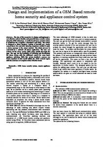
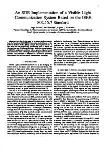
The control buttons are placed on the port A of the microcontroller, and the LCD screen is connected to port B. Users can see the motor rotation direction and angle on the LCD screen and also follow on the interface screen. Serial port communication is provided by port C of microcontroller. Pin connection diagram of the PIC is given in Fig. 2. The BDX53 silicon power transistors are used to drive the stepper motor and they are triggered over port D. Two LEDs are connected to port E to symbolize the turning direction. Blue led indicates that the motor rotates in the forward direction, the red one indicates that the motor rotates in the reverse direction. Driver circuit is fed with an adjustable power supply and being on or off with a switch. A general block diagram of the system designed is given Fig. 3. A client-server environment is designed and implemented. Since the ASP.NET is an objectoriented program, web interfaces are prepared in a more functional and easy way. Main reasons to prefer ASP.NET are providing and creating interactive applications that can work together with databases and easier presenting the prepared sites.
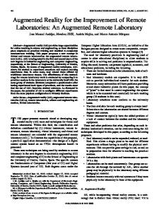
The number of steps required to make one cycle of the rotor (S); (2) S = 360 ° / θ s The rotor speed (n); (3) n = (60 × f ) / S Although recently produced stepper motors have a wide range of type such as solenoid, variable reluctance, hybrid, permanent magnet rotor, permanent magnet stator and electromechanical types, the most widely used types are variable reluctance step motors, permanent magnet step motors, hybrid step motors. Other types of stepper motor are manufactured based on these designs [3]. Visual Studio and CCS C software programs are used as software units in this study. The proposed system is firstly simulated in Proteus to realize the system. Max232 chip has been used for converting the data sent from Virtual Terminal into understandable signals for microcontroller, and the same way detecting the data sent by microcontroller to the computer. To generate clock signal of microcontroller, a 4 MHz crystal oscillator has been used. Also, 7805 voltage regulators have been used to supply regulated 5V voltage for the LCD screen and microcontroller. In addition, a 7809 voltage regulator is used to feed the motor on secure voltage levels. The schematic circuit of the system in Proteus is given in Fig. 1.
DS3e.5-2
Fig. 1. Schematic circuit of the system in Proteus.
Fig. 2. Pin connections of PIC16F877.
Fig. 3. A general block diagram of the system.
In order to provide control operations over the user interface, required signals are applied to the transistors through the PowerDAQ card which has been attached on the computer's PCI bus. In addition to the buttons connected to the circuit, external input sockets are available to drive the motor with the signals sent over the data acquisition card. Resistors to limit current and diodes to prevent applying opposite polarity voltage are connected in series to per socket. The stepper motor used in the circuit has such features as four-phase, permanent magnet and with 7.5° step angle [10]. A picture of the motor driver is given in Fig. 4. When user presses the Half Step Forward button on the circuit or on the user interface, the motor starts to turn forward direction by using the half_step[] movement code as seen in the Fig. 5. When motor rotates in the forward direction, the blue LED is energized and user can also see the direction data on the LCD screen and in the textbox on the interface. As long as the Stop button is pressed, motor will continue to spin on the same direction, and the other buttons will not be active. In Fig. 6, it is shown that turning direction is right and rotor angle is increasing. While motor is turning to any direction, users cannot change the direction. But user can stop the motor by the Stop button and can increase or decrease the rotation speed with the speed adjust buttons. On half step turns, a step-angle becomes half of the full step angle and the total angle increases 3.75° for every step.
Fig. 5. Half Step movement table and rotor position.
Fig. 6. Motor turning to forward
Fig. 7. Full Step movement table and rotor position.
Fig. 4. General view of the circuit.
In the same way, when the Full Step Forward button is pressed, motor starts to rotate in the same direction by using the full_step[] movement code table as seen in the Fig. 7. But at this time every angle increment on the LCD screen will be 7.5° slices that equal to the each step angle. In order to stop the motor, it is enough to press the Stop button on the circuit or on the interface. When the Half Step Backward button is pressed from the circuit or on the interface, the motor is energized and starts to turn backwards. While the motor rotates into backward direction, red LED is energized and user can also see the direction data on LCD screen and in the textbox on the interface as seen in Fig. 8.
DS3e.5-3
Fig. 8. Motor turning to backwards.
To prevent the logical complexity, motor rotation direction cannot be changed unless pushing the Stop button. The flow chart of the program which has been created and installed in the microcontroller is shown in Fig. 9. Buttons in software interface drives the motor by sending the necessary numerical information to digital I/O ports of the PowerDAQ card. In addition, String characters are sent to the interface from the driver circuit for the motor rotation and angle information. For instance, while the serial port communication is being used, if the motor is rotating in the forward direction PIC16F877 writes 'FORW' string to the serial port and writes 'BACK' string information for the opposite direction. If different information from the direction strings is written to the serial port, it is accepted as rotation angle information and sent to the Textbox on the interface. The created interface screen is shown in Fig. 10. III. CONCLUSION Stepper motors are widely used due to having many outstanding features in terms of location or position control in precision mechanical movement. In this study, internet based remote controlling of a step motor training set consisting of microcontroller and DAQ units has been developed. The system basically includes such software and hardware units as ASP.NET and CCS C programs, PowerDAQ data acquisition card, PIC16F877 microprocessor, stepper motor drive circuit and other peripheral sub-units. Users can use the system both locally through the microprocessor based driver card and through internet by using the data acquisition card. In this respect, the designed project has an importance that includes stepper motor driving techniques and shows how the communication infrastructures are provided between computer and peripheral units. The system can be used for educational purposes on the experiments of the step motor drive in engineering and technical education schools, vocational schools and related classes of high schools.
Fig. 9. The flow chart of the program installed in the microcontroller.
Fig. 10. Interface designed with ASP.NET.
DS3e.5-4
REFERENCES [1] [2] [3] [4] [5]
G. Bal, Special electrical machines, 3rd ed., Seckin Press, Ankara, 2006. T. Kenjo, A. Sugawara, Stepping Motors And Their Microprocessor Controls, 2nd ed., Clarendon Press, 1994. H. Apaydın, “Characteristics of Step Motors and Position Control Application with Computer”, M.S. dissertation, Institute of Science and Technology, Marmara Univ , Istanbul, 2006. H. Kaygısız, K. Cetinkaya, “CNC milling training set design and implementation”, SDU International Journal of Technologic Sciences, Vol. 2, No 3, pp. 53-71, 2010 . O. Altınkurt,M. Kahriman,”Real time color based object recognization with anfis and tracking with a stepper motor”, SDU Journal of Technical Sciences, Vol. 1, No 1, pp. 1-5, 2011.
[6]
G. Bal, E. Bekiroglu,”Design and implementation of digitally controlled step motor drives for toothbrush/dentifrice mechanism", Journal of Medical Systems ,Vol. 23, Issue 1, pp. 27-33, Plenum Press, New York, 1999. [7] E. Irmak, “Internet-based remote educational laboratory practice", Institute of Science and Technology, M. of Ph. Thesis, Gazi University. Ankara, 2007. [8] S. Cicek, PIC Programming with CCS C, Altas Press, November 2007. [9] M. R. Samady,M. R. Movahedin, M. Fakhraie, “Implementation of serial port interconnections for integrated circuits", VLSI Circuits and Systems Laboratory, University of Tehran, IRAN. [10] PM55L Data Sheet, Permanent Magnet Stepper Motors, MinebeaMatsushita Motor Corporation Inc., 2004. [11] Jones, D.W., “Stepping Motor Fundamentals”, Microchip Technology Inc., AN907, University of Iowa, United States, 2004.
DS3e.5-5